water pump DODGE NEON 2000 Service Repair Manual
[x] Cancel search | Manufacturer: DODGE, Model Year: 2000, Model line: NEON, Model: DODGE NEON 2000Pages: 1285, PDF Size: 29.42 MB
Page 157 of 1285
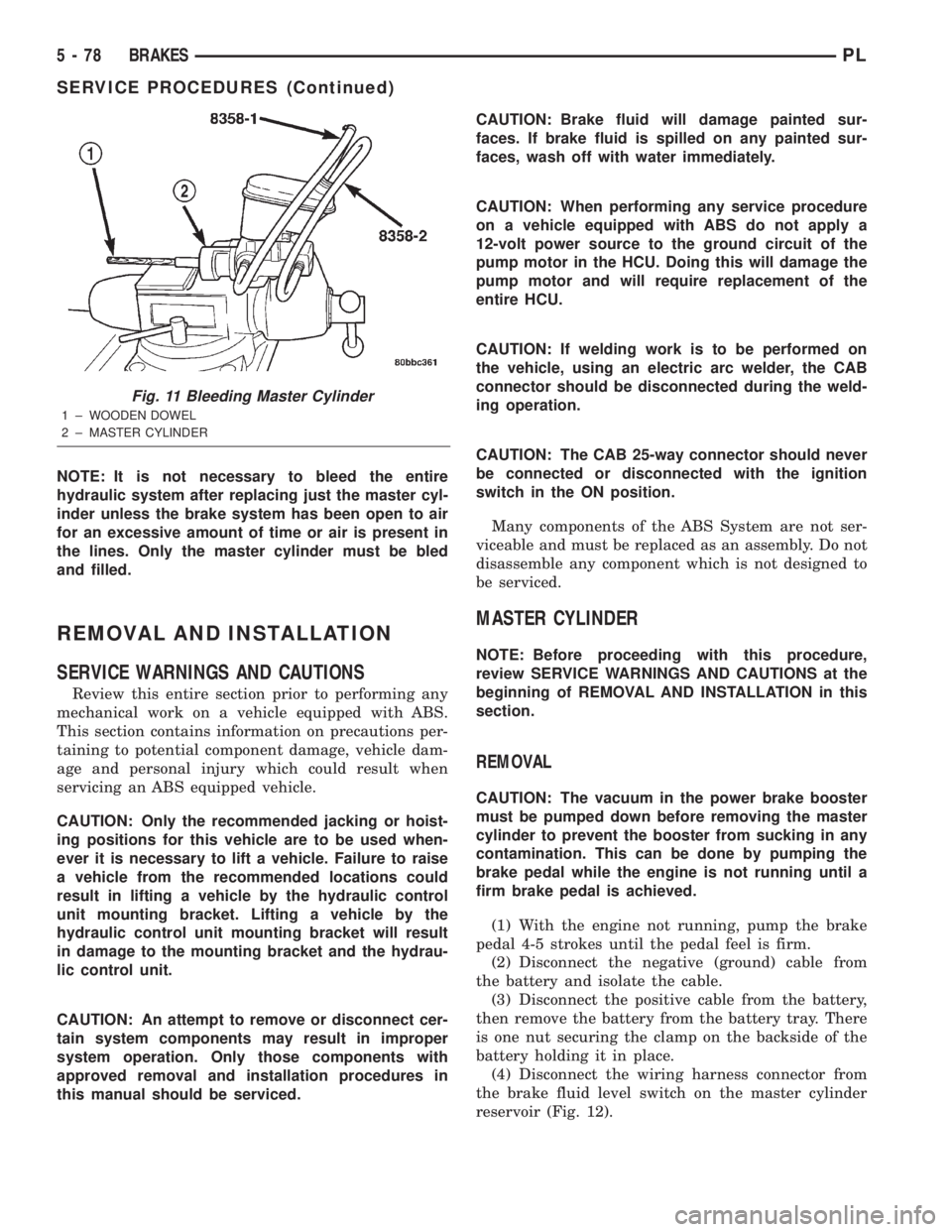
NOTE: It is not necessary to bleed the entire
hydraulic system after replacing just the master cyl-
inder unless the brake system has been open to air
for an excessive amount of time or air is present in
the lines. Only the master cylinder must be bled
and filled.
REMOVAL AND INSTALLATION
SERVICE WARNINGS AND CAUTIONS
Review this entire section prior to performing any
mechanical work on a vehicle equipped with ABS.
This section contains information on precautions per-
taining to potential component damage, vehicle dam-
age and personal injury which could result when
servicing an ABS equipped vehicle.
CAUTION: Only the recommended jacking or hoist-
ing positions for this vehicle are to be used when-
ever it is necessary to lift a vehicle. Failure to raise
a vehicle from the recommended locations could
result in lifting a vehicle by the hydraulic control
unit mounting bracket. Lifting a vehicle by the
hydraulic control unit mounting bracket will result
in damage to the mounting bracket and the hydrau-
lic control unit.
CAUTION: An attempt to remove or disconnect cer-
tain system components may result in improper
system operation. Only those components with
approved removal and installation procedures in
this manual should be serviced.CAUTION: Brake fluid will damage painted sur-
faces. If brake fluid is spilled on any painted sur-
faces, wash off with water immediately.
CAUTION: When performing any service procedure
on a vehicle equipped with ABS do not apply a
12-volt power source to the ground circuit of the
pump motor in the HCU. Doing this will damage the
pump motor and will require replacement of the
entire HCU.
CAUTION: If welding work is to be performed on
the vehicle, using an electric arc welder, the CAB
connector should be disconnected during the weld-
ing operation.
CAUTION: The CAB 25-way connector should never
be connected or disconnected with the ignition
switch in the ON position.
Many components of the ABS System are not ser-
viceable and must be replaced as an assembly. Do not
disassemble any component which is not designed to
be serviced.
MASTER CYLINDER
NOTE: Before proceeding with this procedure,
review SERVICE WARNINGS AND CAUTIONS at the
beginning of REMOVAL AND INSTALLATION in this
section.
REMOVAL
CAUTION: The vacuum in the power brake booster
must be pumped down before removing the master
cylinder to prevent the booster from sucking in any
contamination. This can be done by pumping the
brake pedal while the engine is not running until a
firm brake pedal is achieved.
(1) With the engine not running, pump the brake
pedal 4-5 strokes until the pedal feel is firm.
(2) Disconnect the negative (ground) cable from
the battery and isolate the cable.
(3) Disconnect the positive cable from the battery,
then remove the battery from the battery tray. There
is one nut securing the clamp on the backside of the
battery holding it in place.
(4) Disconnect the wiring harness connector from
the brake fluid level switch on the master cylinder
reservoir (Fig. 12).
Fig. 11 Bleeding Master Cylinder
1 ± WOODEN DOWEL
2 ± MASTER CYLINDER
5 - 78 BRAKESPL
SERVICE PROCEDURES (Continued)
Page 180 of 1285
COOLING SYSTEM
TABLE OF CONTENTS
page page
DESCRIPTION AND OPERATION
COOLING SYSTEM........................1
COOLANT...............................2
COOLANT PERFORMANCE..................2
COOLANT RECOVERY SYSTEM..............3
ENGINE THERMOSTAT.....................3
RADIATOR..............................3
RADIATOR COOLING FAN MODULE...........3
COOLING SYSTEM PRESSURE CAP..........4
RADIATOR HOSES AND CLAMPS............5
WATER PUMP...........................5
AUTOMATIC TRANSMISSION OIL COOLER.....6
ACCESSORY DRIVE BELTS.................6
ENGINE BLOCK HEATER...................6
DIAGNOSIS AND TESTING
COOLING SYSTEM DIAGNOSIS..............7
ENGINE THERMOSTAT TESTING............14
ACCESSORY DRIVE BELT DIAGNOSIS........14
WATER PUMP DIAGNOSIS................15
COOLING SYSTEM FLOW CHECK...........15
ELECTRIC FAN MOTOR TEST...............15
COOLANT CONCENTRATION TESTING........15
TESTING COOLING SYSTEM FOR LEAKS.....15
PRESSURE CAP TO FILLER NECK SEAL
PRESSURE RELIEF CHECK...............16
PRESSURE TESTING COOLING SYSTEM
PRESSURE CAP.......................16
LOW COOLANT LEVEL AERATION...........17
DEAERATION...........................17
TEMPERATURE GAUGE INDICATION.........17
ENGINE BLOCK HEATER..................17
SERVICE PROCEDURES
COOLANT LEVEL CHECKÐROUTINE.........17COOLANTÐADDING ADDITIONAL...........18
COOLANT LEVELÐSERVICING.............18
COOLING SYSTEMÐDRAINING.............19
COOLING SYSTEMÐREFILLING............19
REMOVAL AND INSTALLATION
WATER PUMP..........................19
WATER PUMP INLET TUBE................20
ENGINE THERMOSTAT....................20
RADIATOR.............................21
RADIATOR DRAINCOCK...................22
COOLING FAN MODULE...................22
COOLANT RECOVERY CONTAINER..........23
ENGINE BLOCK HEATER..................24
ACCESSORY DRIVE BELTS................24
AUTOMATIC BELT TENSIONER & PULLEY....26
DISASSEMBLY AND ASSEMBLY
COOLING FAN MODULE...................26
CLEANING AND INSPECTION
WATER PUMP..........................28
ACCESSORY DRIVE BELT INSPECTION.......28
COOLING SYSTEM CAP...................28
COOLING SYSTEM CLEANING..............28
RADIATOR FLUSHING....................28
REVERSE FLUSHING.....................29
CHEMICAL CLEANING....................29
ADJUSTMENTS
BELT TENSION..........................29
SPECIFICATIONS
COOLING SYSTEM CAPACITY..............30
TORQUE SPECIFICATIONS.................30
SPECIAL TOOLS
COOLING..............................30
DESCRIPTION AND OPERATION
COOLING SYSTEM
The cooling system consists of an engine cooling
module, thermostat, coolant, and a water pump to
circulate the coolant. The engine cooling module may
consist of a radiator, electric fan motor, fan, shroud,
coolant reserve system, transmission oil cooler, hoses,clamps, air conditioning condenser and transmission
oil lines.
²When the Engine is cold: The thermostat is
closed and the cooling system has no flow through
the radiator. The coolant flows through the engine,
heater system and bypass.
²When the Engine is warm: Thermostat is open
and the cooling system has flow through the radiator,
engine, heater system, and bypass.
PLCOOLING SYSTEM 7 - 1
Page 181 of 1285
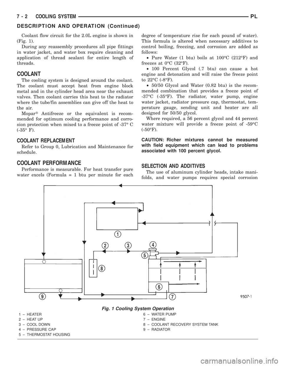
Coolant flow circuit for the 2.0L engine is shown in
(Fig. 1).
During any reassembly procedures all pipe fittings
in water jacket, and water box require cleaning and
application of thread sealant for entire length of
threads.
COOLANT
The cooling system is designed around the coolant.
The coolant must accept heat from engine block
metal and in the cylinder head area near the exhaust
valves. Then coolant carries this heat to the radiator
where the tube/fin assemblies can give off the heat to
the air.
MopartAntifreeze or the equivalent is recom-
mended for optimum cooling performance and corro-
sion protection when mixed to a freeze point of -37É C
(-35É F).
COOLANT REPLACEMENT
Refer to Group 0, Lubrication and Maintenance for
schedule.
COOLANT PERFORMANCE
Performance is measurable. For heat transfer pure
water excels (Formula = 1 btu per minute for eachdegree of temperature rise for each pound of water).
This formula is altered when necessary additives to
control boiling, freezing, and corrosion are added as
follows:
²Pure Water (1 btu) boils at 100ÉC (212ÉF) and
freezes at 0ÉC (32ÉF).
²100 Percent Glycol (.7 btu) can cause a hot
engine and detonation and will raise the freeze point
to 22ÉC (-8ÉF).
²50/50 Glycol and Water (0.82 btu) is the recom-
mended combination that provides a freeze point of
-37ÉC (-35ÉF). The radiator, water pump, engine
water jacket, radiator pressure cap, thermostat, tem-
perature gauge, sending unit and heater are all
designed for 50/50 glycol.
Where required, a 56 percent glycol and 44 percent
water mixture will provide a freeze point of -59ÉC
(-50ÉF).
CAUTION: Richer mixtures cannot be measured
with field equipment which can lead to problems
associated with 100 percent glycol.SELECTION AND ADDITIVES
The use of aluminum cylinder heads, intake mani-
folds, and water pumps requires special corrosion
Fig. 1 Cooling System Operation
1 ± HEATER
2 ± HEAT UP
3 ± COOL DOWN
4 ± PRESSURE CAP
5 ± THERMOSTAT HOUSING6 ± WATER PUMP
7 ± ENGINE
8 ± COOLANT RECOVERY SYSTEM TANK
9 ± RADIATOR
7 - 2 COOLING SYSTEMPL
DESCRIPTION AND OPERATION (Continued)
Page 184 of 1285
RADIATOR HOSES AND CLAMPS
WARNING: IF VEHICLE HAS BEEN RUN RECENTLY,
WAIT 15 MINUTES BEFORE WORKING ON VEHI-
CLE. RELIEVE PRESSURE BY PLACING A SHOP
TOWEL OVER THE CAP AND WITHOUT PUSHING
DOWN ROTATE IT COUNTERCLOCKWISE TO THE
FIRST STOP. ALLOW FLUIDS TO ESCAPE
THROUGH THE OVERFLOW TUBE AND WHEN THE
SYSTEM STOPS PUSHING OUT COOLANT AND
STEAM AND THE PRESSURE DROPS CONTINUE
SERVICE.
WARNING: CONSTANT TENSION HOSE CLAMPS
ARE USED ON MOST COOLING SYSTEM HOSES.
WHEN REMOVING OR INSTALLING, USE ONLY
TOOLS DESIGNED FOR SERVICING THIS TYPE OF
CLAMP. ALWAYS WEAR SAFETY GLASSES WHEN
SERVICING CONSTANT TENSION CLAMPS.
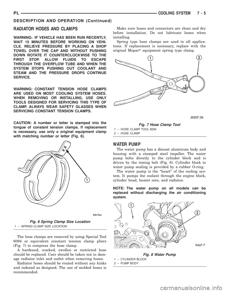
CAUTION: A number or letter is stamped into the
tongue of constant tension clamps. If replacement
is necessary, use only a original equipment clamp
with matching number or letter (Fig. 6).
The hose clamps are removed by using Special Tool
6094 or equivalent constant tension clamp pliers
(Fig. 7) to compress the hose clamp.
A hardened, cracked, swollen or restricted hose
should be replaced. Care should be taken not to dam-
age radiator inlet and outlet when removing hoses.
Radiator hoses should be routed without any kinks
and indexed as designed. The use of molded hoses is
recommended.Make sure hoses and connectors are clean and dry
before installation. Do not lubricate hoses when
installing.
Spring type hose clamps are used in all applica-
tions. If replacement is necessary, replace with the
original Mopartequipment spring type clamp.
WATER PUMP
The water pump has a diecast aluminum body and
housing with a stamped steel impeller. The water
pump bolts directly to the cylinder block and is
driven by the timing belt (Fig. 8). Cylinder block to
water pump sealing is provided by a rubber O-ring.
The water pump is the ªheartº of the cooling sys-
tem. It pumps the coolant through the engine block,
cylinder head, heater core, and radiator.
NOTE: The water pump on all models can be
replaced without discharging the air conditioning
system.
Fig. 6 Spring Clamp Size Location
1 ± SPRING CLAMP SIZE LOCATION
Fig. 7 Hose Clamp Tool
1 ± HOSE CLAMP TOOL 6094
2 ± HOSE CLAMP
Fig. 8 Water Pump
1 ± CYLINDER BLOCK
2 ± PUMP BODY
PLCOOLING SYSTEM 7 - 5
DESCRIPTION AND OPERATION (Continued)
Page 188 of 1285
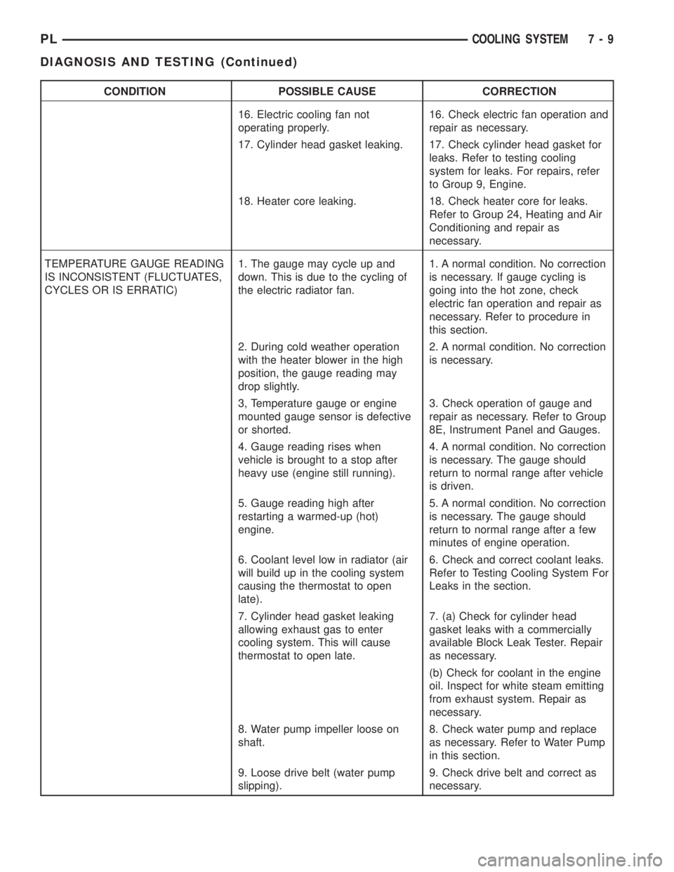
CONDITION POSSIBLE CAUSE CORRECTION
16. Electric cooling fan not
operating properly.16. Check electric fan operation and
repair as necessary.
17. Cylinder head gasket leaking. 17. Check cylinder head gasket for
leaks. Refer to testing cooling
system for leaks. For repairs, refer
to Group 9, Engine.
18. Heater core leaking. 18. Check heater core for leaks.
Refer to Group 24, Heating and Air
Conditioning and repair as
necessary.
TEMPERATURE GAUGE READING
IS INCONSISTENT (FLUCTUATES,
CYCLES OR IS ERRATIC)1. The gauge may cycle up and
down. This is due to the cycling of
the electric radiator fan.1. A normal condition. No correction
is necessary. If gauge cycling is
going into the hot zone, check
electric fan operation and repair as
necessary. Refer to procedure in
this section.
2. During cold weather operation
with the heater blower in the high
position, the gauge reading may
drop slightly.2. A normal condition. No correction
is necessary.
3, Temperature gauge or engine
mounted gauge sensor is defective
or shorted.3. Check operation of gauge and
repair as necessary. Refer to Group
8E, Instrument Panel and Gauges.
4. Gauge reading rises when
vehicle is brought to a stop after
heavy use (engine still running).4. A normal condition. No correction
is necessary. The gauge should
return to normal range after vehicle
is driven.
5. Gauge reading high after
restarting a warmed-up (hot)
engine.5. A normal condition. No correction
is necessary. The gauge should
return to normal range after a few
minutes of engine operation.
6. Coolant level low in radiator (air
will build up in the cooling system
causing the thermostat to open
late).6. Check and correct coolant leaks.
Refer to Testing Cooling System For
Leaks in the section.
7. Cylinder head gasket leaking
allowing exhaust gas to enter
cooling system. This will cause
thermostat to open late.7. (a) Check for cylinder head
gasket leaks with a commercially
available Block Leak Tester. Repair
as necessary.
(b) Check for coolant in the engine
oil. Inspect for white steam emitting
from exhaust system. Repair as
necessary.
8. Water pump impeller loose on
shaft.8. Check water pump and replace
as necessary. Refer to Water Pump
in this section.
9. Loose drive belt (water pump
slipping).9. Check drive belt and correct as
necessary.
PLCOOLING SYSTEM 7 - 9
DIAGNOSIS AND TESTING (Continued)
Page 189 of 1285
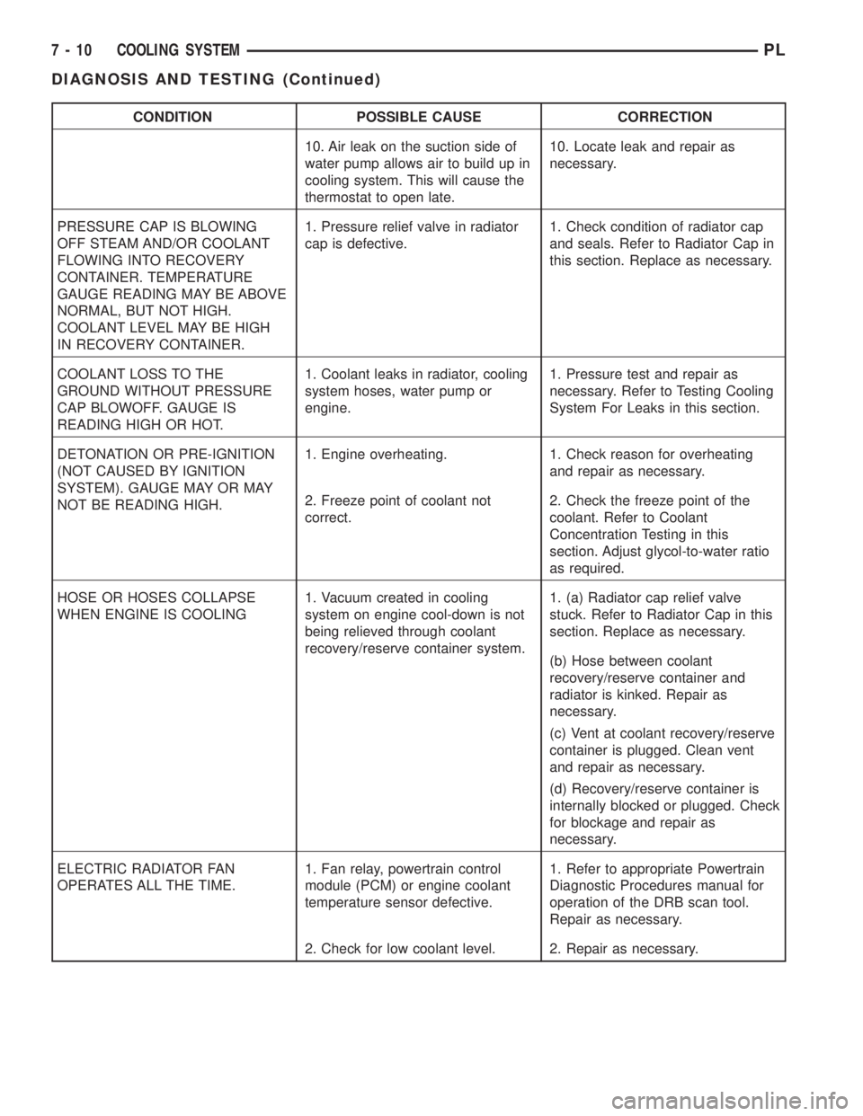
CONDITION POSSIBLE CAUSE CORRECTION
10. Air leak on the suction side of
water pump allows air to build up in
cooling system. This will cause the
thermostat to open late.10. Locate leak and repair as
necessary.
PRESSURE CAP IS BLOWING
OFF STEAM AND/OR COOLANT
FLOWING INTO RECOVERY
CONTAINER. TEMPERATURE
GAUGE READING MAY BE ABOVE
NORMAL, BUT NOT HIGH.
COOLANT LEVEL MAY BE HIGH
IN RECOVERY CONTAINER.1. Pressure relief valve in radiator
cap is defective.1. Check condition of radiator cap
and seals. Refer to Radiator Cap in
this section. Replace as necessary.
COOLANT LOSS TO THE
GROUND WITHOUT PRESSURE
CAP BLOWOFF. GAUGE IS
READING HIGH OR HOT.1. Coolant leaks in radiator, cooling
system hoses, water pump or
engine.1. Pressure test and repair as
necessary. Refer to Testing Cooling
System For Leaks in this section.
DETONATION OR PRE-IGNITION
(NOT CAUSED BY IGNITION
SYSTEM). GAUGE MAY OR MAY
NOT BE READING HIGH.1. Engine overheating. 1. Check reason for overheating
and repair as necessary.
2. Freeze point of coolant not
correct.2. Check the freeze point of the
coolant. Refer to Coolant
Concentration Testing in this
section. Adjust glycol-to-water ratio
as required.
HOSE OR HOSES COLLAPSE
WHEN ENGINE IS COOLING1. Vacuum created in cooling
system on engine cool-down is not
being relieved through coolant
recovery/reserve container system.1. (a) Radiator cap relief valve
stuck. Refer to Radiator Cap in this
section. Replace as necessary.
(b) Hose between coolant
recovery/reserve container and
radiator is kinked. Repair as
necessary.
(c) Vent at coolant recovery/reserve
container is plugged. Clean vent
and repair as necessary.
(d) Recovery/reserve container is
internally blocked or plugged. Check
for blockage and repair as
necessary.
ELECTRIC RADIATOR FAN
OPERATES ALL THE TIME.1. Fan relay, powertrain control
module (PCM) or engine coolant
temperature sensor defective.1. Refer to appropriate Powertrain
Diagnostic Procedures manual for
operation of the DRB scan tool.
Repair as necessary.
2. Check for low coolant level. 2. Repair as necessary.
7 - 10 COOLING SYSTEMPL
DIAGNOSIS AND TESTING (Continued)
Page 191 of 1285
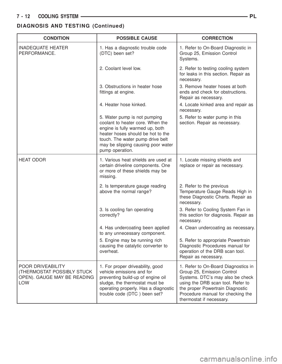
CONDITION POSSIBLE CAUSE CORRECTION
INADEQUATE HEATER
PERFORMANCE.1. Has a diagnostic trouble code
(DTC) been set?1. Refer to On-Board Diagnostic in
Group 25, Emission Control
Systems.
2. Coolant level low. 2. Refer to testing cooling system
for leaks in this section. Repair as
necessary.
3. Obstructions in heater hose
fittings at engine.3. Remove heater hoses at both
ends and check for obstructions.
Repair as necessary.
4. Heater hose kinked. 4. Locate kinked area and repair as
necessary.
5. Water pump is not pumping
coolant to heater core. When the
engine is fully warmed up, both
heater hoses should be hot to the
touch. The water pump drive belt
may be slipping causing poor water
pump operation.5. Refer to water pump in this
section. Repair as necessary.
HEAT ODOR 1. Various heat shields are used at
certain driveline components. One
or more of these shields may be
missing.1. Locate missing shields and
replace or repair as necessary.
2. Is temperature gauge reading
above the normal range?2. Refer to the previous
Temperature Gauge Reads High in
these Diagnostic Charts. Repair as
necessary.
3. Is cooling fan operating
correctly?3. Refer to Cooling System Fan in
this section for diagnosis. Repair as
necessary.
4. Has undercoating been applied
to any unnecessary component.4. Clean undercoating as necessary.
5. Engine may be running rich
causing the catalytic converter to
overheat.5. Refer to appropriate Powertrain
Diagnostic Procedures manual for
operation of the DRB scan tool.
Repair as necessary.
POOR DRIVEABILITY
(THERMOSTAT POSSIBLY STUCK
OPEN). GAUGE MAY BE READING
LOW1. For proper driveability, good
vehicle emissions and for
preventing build-up of engine oil
sludge, the thermostat must be
operating properly. Has a diagnostic
trouble code (DTC ) been set?1. Refer to On-Board Diagnostics in
Group 25, Emission Control
Systems. DTC's may also be check
using the DRB scan tool. Refer to
the proper Powertrain Diagnostic
Procedure manual for checking the
thermostat if necessary.
7 - 12 COOLING SYSTEMPL
DIAGNOSIS AND TESTING (Continued)
Page 193 of 1285
ENGINE THERMOSTAT TESTING
The thermostat is operated by a wax filled con-
tainer (pellet) which is sealed. When heated coolant
reaches a predetermined temperature the wax pellet
expands enough to overcome the closing spring and
water pump pressure, which forces the valve to open.
Coolant leakage into the pellet will cause a thermo-
stat to fail open. Do not attempt to free up a thermo-
stat with a screwdriver.
The thermostat that opens too soon type failure
mode is included in the on-board diagnosis. Thecheck engine light will not be lit by an open too soon
condition. If it has failed open, a diagnostic trouble
code (DTC) will be set. Do not change a thermostat
for lack of heater performance or temperature gauge
position, unless a DTC is present. See Diagnosis for
other probable causes. Thermostat failing shut is the
normal long term mode of failure, and normally, only
on high mileage vehicles. The temperature gauge will
indicate this. Refer to Diagnosis in this section.
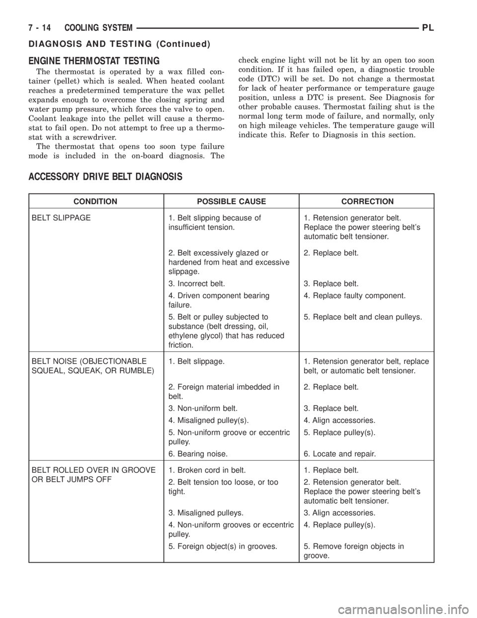
ACCESSORY DRIVE BELT DIAGNOSIS
CONDITION POSSIBLE CAUSE CORRECTION
BELT SLIPPAGE 1. Belt slipping because of
insufficient tension.1. Retension generator belt.
Replace the power steering belt's
automatic belt tensioner.
2. Belt excessively glazed or
hardened from heat and excessive
slippage.2. Replace belt.
3. Incorrect belt. 3. Replace belt.
4. Driven component bearing
failure.4. Replace faulty component.
5. Belt or pulley subjected to
substance (belt dressing, oil,
ethylene glycol) that has reduced
friction.5. Replace belt and clean pulleys.
BELT NOISE (OBJECTIONABLE
SQUEAL, SQUEAK, OR RUMBLE)1. Belt slippage. 1. Retension generator belt, replace
belt, or automatic belt tensioner.
2. Foreign material imbedded in
belt.2. Replace belt.
3. Non-uniform belt. 3. Replace belt.
4. Misaligned pulley(s). 4. Align accessories.
5. Non-uniform groove or eccentric
pulley.5. Replace pulley(s).
6. Bearing noise. 6. Locate and repair.
BELT ROLLED OVER IN GROOVE
OR BELT JUMPS OFF1. Broken cord in belt. 1. Replace belt.
2. Belt tension too loose, or too
tight.2. Retension generator belt.
Replace the power steering belt's
automatic belt tensioner.
3. Misaligned pulleys. 3. Align accessories.
4. Non-uniform grooves or eccentric
pulley.4. Replace pulley(s).
5. Foreign object(s) in grooves. 5. Remove foreign objects in
groove.
7 - 14 COOLING SYSTEMPL
DIAGNOSIS AND TESTING (Continued)
Page 194 of 1285
WATER PUMP DIAGNOSIS
A quick flow test to tell whether or not the pump is
working is to see if the heater warms properly. A
defective pump will not be able to circulate heated
coolant through the long heater hose.
Another flow test to help determine pump opera-
tion:
WARNING: DO NOT remove radiator cap if the cool-
ing system is hot or under pressure.
(1) Remove cooling system pressure cap.
(2) Remove a small amount of coolant from the
system.
(3) Start the engine and warm up until thermostat
opens.
(4) With the thermostat open and coolant level low,
visually inspect for coolant flow. If flow is present,
the water pump is pumping coolant through the sys-
tem.
COOLING SYSTEM FLOW CHECK
To determine whether coolant is flowing through
the cooling system, use the following procedures:
(1) If engine is cold, idle engine until normal oper-
ating temperature is reached. Then feel the upper
radiator hose. If it is hot, coolant is circulating.
WARNING: DO NOT REMOVE THE COOLING SYS-
TEM PRESSURE CAP WITH THE SYSTEM HOT AND
UNDER PRESSURE BECAUSE SERIOUS BURNS
FROM COOLANT CAN OCCUR.
(2) Remove pressure cap when engine is cold,
remove small amount of coolant Idle engine until
thermostat opens, you should observe coolant flow
while looking down the filler neck. Once flow is
detected install the pressure cap.
ELECTRIC FAN MOTOR TEST
Refer to Powertrain Diagnostic Manual for proce-
dure.
COOLANT CONCENTRATION TESTING
Coolant concentration should be checked when any
additional coolant was added to system or after a
coolant drain, flush and refill. The coolant mixture
offers optimum engine cooling and protection against
corrosion when mixed to a freeze point of -37ÉC
(-34ÉF) to -59ÉC (-50ÉF). The use of a hydrometer or a
refractometer can be used to test coolant concentra-
tion.
A hydrometer will test the amount of glycol in a
mixture by measuring the specific gravity of the mix-
ture. The higher the concentration of ethylene glycol,
the larger the number of balls that will float, andhigher the freeze protection (up to a maximum of
70% by volume glycol).
A refractometer will test the amount of glycol in a
coolant mixture by measuring the amount a beam of
light bends as it passes through the fluid.
Some coolant manufactures use other types of gly-
cols into their coolant formulations. Propylene glycol
is the most common new coolant. However, propylene
glycol based coolants do not provide the same freez-
ing protection and corrosion protection and is only
recommended for limited usage. Refer to appropriate
Technical Service Bulletin(s) regarding use of propy-
lene glycol based coolants.
CAUTION: Do not mix types of coolantÐcorrosion
protection will be severely reduced.
Because ethylene glycol and propylene glycol do
not have the same specific gravities, the use of a
hydrometer will be inaccurate. Therefore, Special
Tool 8286 refractometer, is recommended when test-
ing either ethylene or propylene glycol coolants.
TESTING COOLING SYSTEM FOR LEAKS
The system should be full. With the engine not
running, wipe the filler neck sealing seat clean.
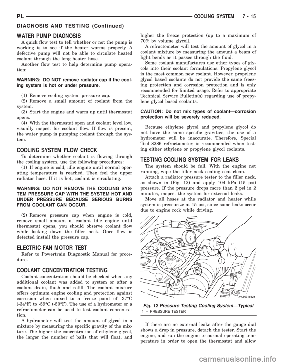
Attach a radiator pressure tester to the filler neck,
as shown in (Fig. 12) and apply 104 kPa (15 psi)
pressure. If the pressure drops more than 2 psi in 2
minutes, inspect the system for external leaks.
Move all hoses at the radiator and heater while
system is pressurize at 15 psi, since some leaks occur
due to engine rock while driving.
If there are no external leaks after the gauge dial
shows a drop in pressure, detach the tester. Start the
engine, and run the engine to normal operating tem-
perature in order to open the thermostat and allow
Fig. 12 Pressure Testing Cooling SystemÐTypical
1 ± PRESSURE TESTER
PLCOOLING SYSTEM 7 - 15
DIAGNOSIS AND TESTING (Continued)
Page 195 of 1285
the coolant to expand. Reattach the tester. If the nee-
dle on the dial fluctuates it indicates a combustion
leak, usually a head gasket leak.
WARNING: WITH THE PRESSURE TESTER IN
PLACE PRESSURE BUILDS UP QUICKLY. ANY
EXCESSIVE PRESSURE BUILD-UP DUE TO CON-
TINUOUS ENGINE OPERATION MUST BE
RELEASED TO A SAFE PRESSURE POINT. NEVER
PERMIT PRESSURE TO EXCEED 138 kPa (20 psi).
If the needle on the dial does not fluctuate, race
the engine a few times. If an abnormal amount of
coolant or steam is emitted from the tail pipe, it may
indicate a faulty head gasket, cracked engine block,
or cracked cylinder head.
There may be internal leaks, which can be deter-
mined by removing the oil dipstick. If water globules
appear intermixed with the oil, it indicates an inter-
nal leak in the engine. If there is an internal leak,
the engine must be disassembled for repair.
PRESSURE CAP TO FILLER NECK SEAL
PRESSURE RELIEF CHECK
The pressure cap upper gasket (seal) pressure
relief can be checked by removing the overflow hose
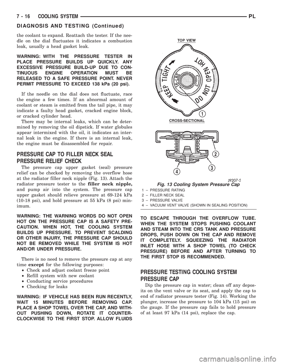
at the radiator filler neck nipple (Fig. 13). Attach the
radiator pressure tester to thefiller neck nipple,
and pump air into the system. The pressure cap
upper gasket should relieve pressure at 69-124 kPa
(10-18 psi), and hold pressure at 55 kPa (8 psi) min-
imum.
WARNING: THE WARNING WORDS DO NOT OPEN
HOT ON THE PRESSURE CAP IS A SAFETY PRE-
CAUTION. WHEN HOT, THE COOLING SYSTEM
BUILDS UP PRESSURE. TO PREVENT SCALDING
OR OTHER INJURY, THE PRESSURE CAP SHOULD
NOT BE REMOVED WHILE THE SYSTEM IS HOT
AND/OR UNDER PRESSURE.
There is no need to remove the pressure cap at any
timeexceptfor the following purposes:
²Check and adjust coolant freeze point
²Refill system with new coolant
²Conducting service procedures
²Checking for leaks
WARNING: IF VEHICLE HAS BEEN RUN RECENTLY,
WAIT 15 MINUTES BEFORE REMOVING CAP.
PLACE A SHOP TOWEL OVER THE CAP, AND WITH-
OUT PUSHING DOWN, ROTATE IT COUNTER-
CLOCKWISE TO THE FIRST STOP. ALLOW FLUIDSTO ESCAPE THROUGH THE OVERFLOW TUBE.
WHEN THE SYSTEM STOPS PUSHING COOLANT
AND STEAM INTO THE CRS TANK AND PRESSURE
DROPS, PUSH DOWN ON THE CAP AND REMOVE
IT COMPLETELY. SQUEEZING THE RADIATOR
INLET HOSE WITH A SHOP TOWEL (TO CHECK
PRESSURE) BEFORE AND AFTER TURNING TO
THE FIRST STOP IS RECOMMENDED.
PRESSURE TESTING COOLING SYSTEM
PRESSURE CAP
Dip the pressure cap in water; clean off any depos-
its on the vent valve or its seat, and apply the cap to
end of radiator pressure tester (Fig. 14). Working the
plunger, increase the pressure to 104 kPa (15 psi) on
the gauge. If the pressure cap fails to hold pressure
of at least 97 kPa (14 psi), replace the cap.
Fig. 13 Cooling System Pressure Cap
1 ± PRESSURE RATING
2 ± FILLER NECK SEAL
3 ± PRESSURE VALVE
4 ± VACUUM VENT VALVE (SHOWN IN SEALING POSITION)
7 - 16 COOLING SYSTEMPL
DIAGNOSIS AND TESTING (Continued)