ECO mode DODGE RAM 1500 1998 2.G Owners Manual
[x] Cancel search | Manufacturer: DODGE, Model Year: 1998, Model line: RAM 1500, Model: DODGE RAM 1500 1998 2.GPages: 2627
Page 2135 of 2627

SHIFT FORKS AND MAINSHAFT
(1) Lubricate mainshaft splines with recommended
transmission fluid.
(2) Install the mode hub (Fig. 55) onto the output
shaft.
(3) Install the mode hub retaining ring (Fig. 56)
onto the output shaft.
(4) Install the sprocket hub (Fig. 57) onto the out-
put shaft.
(5) Install the clutch gear (Fig. 58) onto the output
shaft.
(6) Install the drive sprocket (Fig. 59) onto the out-
put shaft.
Fig. 55 Install Mode Hub
1 - OUTPUT SHAFT
2 - MODE HUB
Fig. 56 Install Mode Hub Retaining Ring
1 - OUTPUT SHAFT
2 - RETAINING RING
3 - MODE HUB
Fig. 57 Install Sprocket Hub
1 - OUTPUT SHAFT
2 - SPROCKET HUB
Fig. 58 Install Clutch Gear
1 - OUTPUT SHAFT
2 - CLUTCH GEAR
3 - MODE HUB
Fig. 59 Install Drive Sprocket
1 - OUTPUT SHAFT
2 - DRIVE SPROCKET
21 - 432 TRANSFER CASE - NV241 GENIIDR
TRANSFER CASE - NV241 GENII (Continued)
Page 2139 of 2627

(5) Install drive chain around mainshaft sprocket
(Fig. 73). Then position front sprocket over front
shaft.
(6) Raise mainshaft about 2.54 cm (one inch) and
seat front sprocket on front output shaft.
(7) If mainshaft and mode sleeve were unseated
during chain installation, align and reseat mainshaft
in input gear and hub.
(8) Install front sprocket retaining ring (Fig. 74).(9) Install spring and cup on shift rail (Fig. 75).
(10) Insert magnet in front case pocket (Fig. 76).
OIL PUMP AND REAR CASE
CAUTION: Do not remove the bolts holding the oil
pump cover to the rear case half. The oil pump
cover is aligned to the rear output shaft inner bear-
ing race and will become mis-aligned if the bolts
are loosened. If the transfer case failure has gener-
ated any debris which may have become trapped in
the oil pump. the rear case and oil pump assembly
MUST be replaced.
(1) Apply bead of MopartGasket Maker, or equiv-
alent, to mating surface of front case. Keep sealer
bead width to maximum of 3/16 inch. Do not use
excessive amount of sealer as excess will be displaced
into case interior.
Fig. 73 Install Front Sprocket and Drive Chain
1 - FRONT DRIVE SPROCKET
2 - DRIVE CHAIN
3 - MAINSHAFT
Fig. 74 Front Sprocket Retaining Ring Installation
1 - FRONT SPROCKET
2 - RETAINING RING
Fig. 75 Shift Rail Spring And Cup Installation
1 - CUP
2 - SPRING
Fig. 76 Case Magnet Installation
1 - MAGNET
2 - CASE POCKET
21 - 436 TRANSFER CASE - NV241 GENIIDR
TRANSFER CASE - NV241 GENII (Continued)
Page 2169 of 2627

(7) Install snap-ring to hold input/low range gear
into front bearing (Fig. 62).
(8) Install a new input gear seal using Installer
8841 and Handle C-4171.
(9) Install a new input gear oil seal with Installer
9036 and Handle C-4171.
SHIFT FORKS AND MAINSHAFT
(1) Lubricate mainshaft splines with recommended
transmission fluid.
(2) Coat the interior of the drive sprocket hub with
ATF+4 and install the drive sprocket drive hub (Fig.
63) onto the mainshaft.(3) Install the mode hub (Fig. 64) onto the main-
shaft.
(4) Install the mode hub retaining ring (Fig. 65)
onto the mainshaft.
Fig. 62 Install Input Gear Retaining Ring
1 - INPUT GEAR
2 - RETAINING RING
Fig. 63 Install the Drive Sprocket Drive Hub
1 - MAINSHAFT
2 - DRIVE SPROCKET DRIVE HUB
Fig. 64 Install Mode Hub
1 - MAINSHAFT
2 - MODE HUB
Fig. 65 Install Mode Hub Retaining Ring
1 - MAINSHAFT
2 - MODE HUB
3 - RETAINING RING
21 - 466 TRANSFER CASE - NV271DR
TRANSFER CASE - NV271 (Continued)
Page 2202 of 2627

(6) Align and install low range/input gear assem-
bly in front case (Fig. 52). Be sure low range gear
pinions are engaged in annulus gear and that input
gear shaft is fully seated in front bearing.
(7) Install snap-ring to hold input/low range gear
into front bearing (Fig. 53).
(8) Install a new input gear seal using Installer
8841 and Handle C-4171.SHIFT FORKS AND MAINSHAFT
(1) Lubricate mainshaft splines with recommended
transmission fluid.
(2) Install the mode hub (Fig. 54) onto the output
shaft.
(3) Install the mode hub retaining ring (Fig. 55)
onto the output shaft.
Fig. 52 Install Input Planetary Assembly
1 - FRONT CASE
2 - INPUT PLANETARY ASSEMBLY
Fig. 53 Install Input Gear Retaining Ring
1 - INPUT GEAR
2 - RETAINING RING
Fig. 54 Install Mode Hub
1 - OUTPUT SHAFT
2 - MODE HUB
Fig. 55 Install Mode Hub Retaining Ring
1 - OUTPUT SHAFT
2 - RETAINING RING
3 - MODE HUB
DRTRANSFER CASE - NV243 21 - 499
TRANSFER CASE - NV243 (Continued)
Page 2212 of 2627

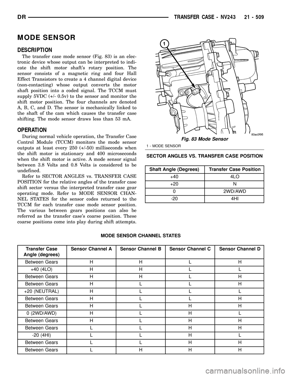
MODE SENSOR
DESCRIPTION
The transfer case mode sensor (Fig. 83) is an elec-
tronic device whose output can be interpreted to indi-
cate the shift motor shaft's rotary position. The
sensor consists of a magnetic ring and four Hall
Effect Transistors to create a 4 channel digital device
(non-contacting) whose output converts the motor
shaft position into a coded signal. The TCCM must
supply 5VDC (+/- 0.5v) to the sensor and monitor the
shift motor position. The four channels are denoted
A, B, C, and D. The sensor is mechanically linked to
the shaft of the cam which causes the transfer case
shifting. The mode sensor draws less than 53 mA.
OPERATION
During normal vehicle operation, the Transfer Case
Control Module (TCCM) monitors the mode sensor
outputs at least every 250 (+/-50) milliseconds when
the shift motor is stationary and 400 microseconds
when the shift motor is active. A mode sensor signal
between 3.8 Volts and 0.8 Volts is considered to be
undefined.
Refer to SECTOR ANGLES vs. TRANSFER CASE
POSITION for the relative angles of the transfer case
shift sector versus the interpreted transfer case gear
operating mode. Refer to MODE SENSOR CHAN-
NEL STATES for the sensor codes returned to the
TCCM for each transfer case mode sensor position.
The various between gears positions can also be
referred as the transfer case's coarse position. These
coarse positions come into play during shift attempts.SECTOR ANGLES VS. TRANSFER CASE POSITION
Shaft Angle (Degrees) Transfer Case Position
+40 4LO
+20 N
0 2WD/AWD
-20 4HI
MODE SENSOR CHANNEL STATES
Transfer Case
Angle (degrees)Sensor Channel A Sensor Channel B Sensor Channel C Sensor Channel D
Between Gears H H L H
+40 (4LO) H H L L
Between Gears H H L H
Between Gears H L L H
+20 (NEUTRAL) H L L L
Between Gears H L L H
Between Gears H L H H
0 (2WD/AWD) H L H L
Between Gears H L H H
Between Gears L L H H
-20 (4HI) L L H L
Between Gears L L H H
Between Gears L H H H
Fig. 83 Mode Sensor
1 - MODE SENSOR
DRTRANSFER CASE - NV243 21 - 509
Page 2230 of 2627

(4) Install remaining thrust washer in low range
gear and on top of input gear. Be sure washer tabs
are properly aligned in gear notches.
(5) Install retainer on input gear and install snap-
ring.
(6) Align and install low range/input gear assem-
bly in front case (Fig. 49). Be sure low range gear
pinions are engaged in annulus gear and that input
gear shaft is fully seated in front bearing.
(7) Install snap-ring to hold input/low range gear
into front bearing (Fig. 50).
(8) Install a new input gear seal using Installer
8841 and Handle C-4171.SHIFT FORKS AND MAINSHAFT
(1) Lubricate mainshaft splines with recommended
transmission fluid.
NOTE: Replace the mode hub retainer if the legs
were distorted during removal.
(2) Install the mode hub retainer (Fig. 51) onto the
mode hub.
(3) Install the mode hub (Fig. 52) and mode hub
retainer onto the differential assembly. Make sure
the retainer is fully seated onto the differential.
Fig. 49 Install Input Planetary Assembly
1 - FRONT CASE
2 - INPUT PLANETARY ASSEMBLY
Fig. 50 Install Input Gear Retaining Ring
1 - INPUT GEAR
2 - RETAINING RING
Fig. 51 Install Retainer onto Mode Hub
1 - MODE HUB RETAINER
2 - MODE HUB
Fig. 52 Install the Mode Hub and Retainer
1 - DIFFERENTIAL ASSEMBLY
2 - MODE HUB AND RETAINER
DRTRANSFER CASE - NV244 GENII 21 - 527
TRANSFER CASE - NV244 GENII (Continued)
Page 2242 of 2627

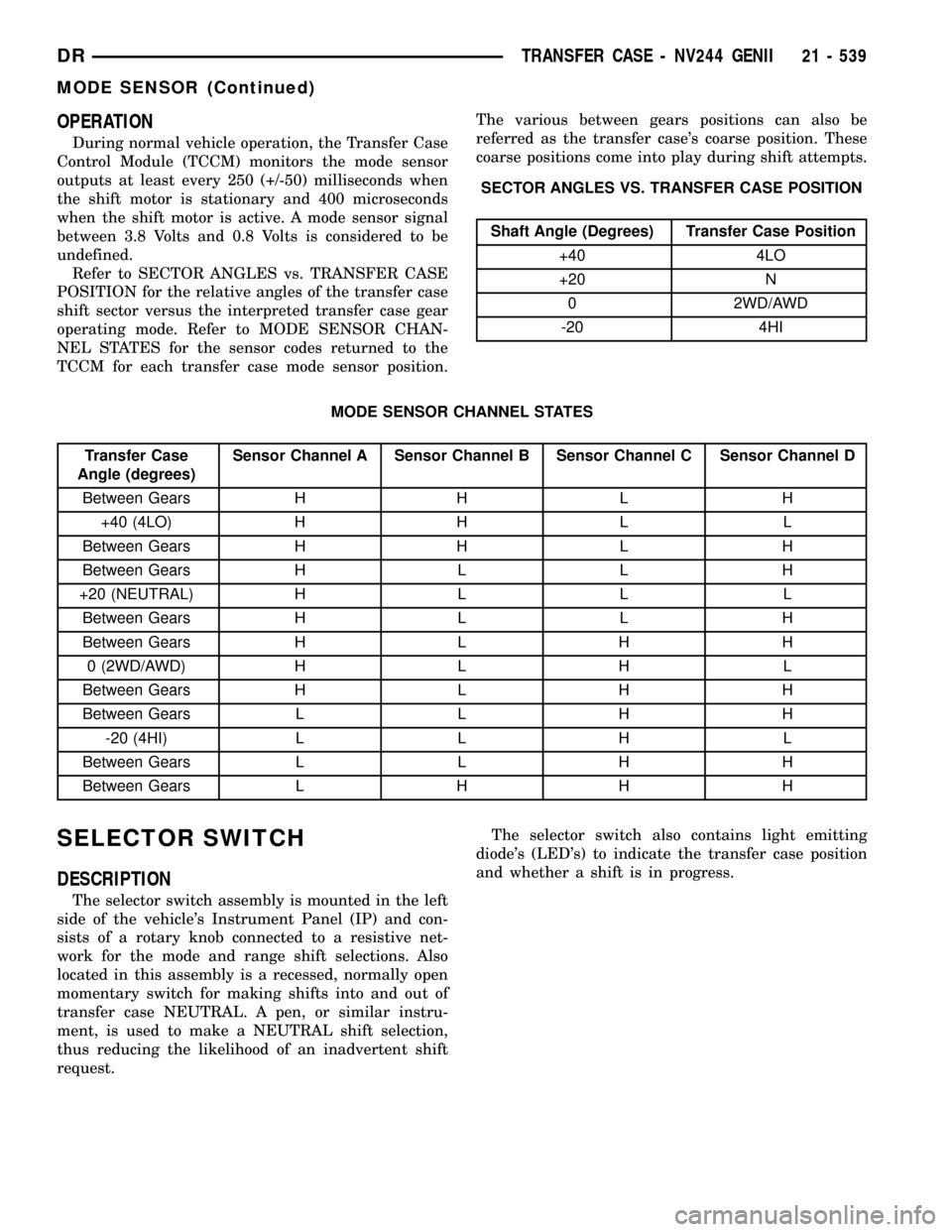
OPERATION
During normal vehicle operation, the Transfer Case
Control Module (TCCM) monitors the mode sensor
outputs at least every 250 (+/-50) milliseconds when
the shift motor is stationary and 400 microseconds
when the shift motor is active. A mode sensor signal
between 3.8 Volts and 0.8 Volts is considered to be
undefined.
Refer to SECTOR ANGLES vs. TRANSFER CASE
POSITION for the relative angles of the transfer case
shift sector versus the interpreted transfer case gear
operating mode. Refer to MODE SENSOR CHAN-
NEL STATES for the sensor codes returned to the
TCCM for each transfer case mode sensor position.The various between gears positions can also be
referred as the transfer case's coarse position. These
coarse positions come into play during shift attempts.
SECTOR ANGLES VS. TRANSFER CASE POSITION
Shaft Angle (Degrees) Transfer Case Position
+40 4LO
+20 N
0 2WD/AWD
-20 4HI
MODE SENSOR CHANNEL STATES
Transfer Case
Angle (degrees)Sensor Channel A Sensor Channel B Sensor Channel C Sensor Channel D
Between Gears H H L H
+40 (4LO) H H L L
Between Gears H H L H
Between Gears H L L H
+20 (NEUTRAL) H L L L
Between Gears H L L H
Between Gears H L H H
0 (2WD/AWD) H L H L
Between Gears H L H H
Between Gears L L H H
-20 (4HI) L L H L
Between Gears L L H H
Between Gears L H H H
SELECTOR SWITCH
DESCRIPTION
The selector switch assembly is mounted in the left
side of the vehicle's Instrument Panel (IP) and con-
sists of a rotary knob connected to a resistive net-
work for the mode and range shift selections. Also
located in this assembly is a recessed, normally open
momentary switch for making shifts into and out of
transfer case NEUTRAL. A pen, or similar instru-
ment, is used to make a NEUTRAL shift selection,
thus reducing the likelihood of an inadvertent shift
request.The selector switch also contains light emitting
diode's (LED's) to indicate the transfer case position
and whether a shift is in progress.
DRTRANSFER CASE - NV244 GENII 21 - 539
MODE SENSOR (Continued)
Page 2264 of 2627

(7) Install snap-ring to hold input/low range gear
into front bearing (Fig. 61).
(8) Install a new input gear seal using Installer
8841 and Handle C-4171.
(9) Install a new input gear oil seal with Installer
9036 and Handle C-4171.
SHIFT FORKS AND MAINSHAFT
(1) Lubricate mainshaft splines with recommended
transmission fluid.
(2) Coat the interior of the drive sprocket hub with
ATF+4 and install the drive sprocket drive hub (Fig.
62) onto the mainshaft.(3) Install the mode hub (Fig. 63) onto the main-
shaft.
(4) Install the mode hub retaining ring (Fig. 64)
onto the mainshaft.
Fig. 61 Install Input Gear Retaining Ring
1 - INPUT GEAR
2 - RETAINING RING
Fig. 62 Install the Drive Sprocket Drive Hub
1 - MAINSHAFT
2 - DRIVE SPROCKET DRIVE HUB
Fig. 63 Install Mode Hub
1 - MAINSHAFT
2 - MODE HUB
Fig. 64 Install Mode Hub Retaining Ring
1 - MAINSHAFT
2 - MODE HUB
3 - RETAINING RING
DRTRANSFER CASE - NV273 21 - 561
TRANSFER CASE - NV273 (Continued)
Page 2276 of 2627

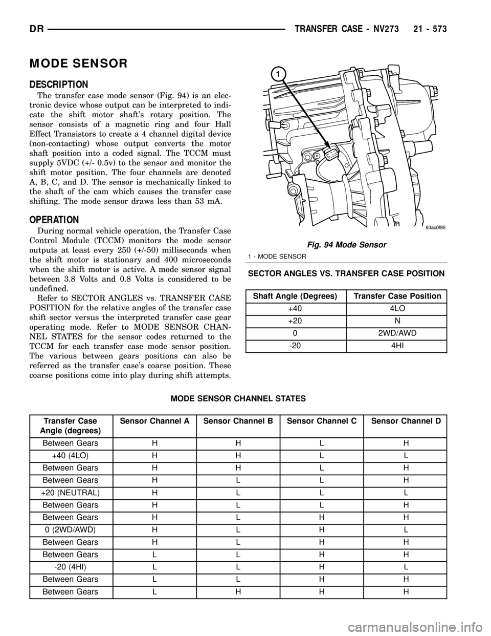
MODE SENSOR
DESCRIPTION
The transfer case mode sensor (Fig. 94) is an elec-
tronic device whose output can be interpreted to indi-
cate the shift motor shaft's rotary position. The
sensor consists of a magnetic ring and four Hall
Effect Transistors to create a 4 channel digital device
(non-contacting) whose output converts the motor
shaft position into a coded signal. The TCCM must
supply 5VDC (+/- 0.5v) to the sensor and monitor the
shift motor position. The four channels are denoted
A, B, C, and D. The sensor is mechanically linked to
the shaft of the cam which causes the transfer case
shifting. The mode sensor draws less than 53 mA.
OPERATION
During normal vehicle operation, the Transfer Case
Control Module (TCCM) monitors the mode sensor
outputs at least every 250 (+/-50) milliseconds when
the shift motor is stationary and 400 microseconds
when the shift motor is active. A mode sensor signal
between 3.8 Volts and 0.8 Volts is considered to be
undefined.
Refer to SECTOR ANGLES vs. TRANSFER CASE
POSITION for the relative angles of the transfer case
shift sector versus the interpreted transfer case gear
operating mode. Refer to MODE SENSOR CHAN-
NEL STATES for the sensor codes returned to the
TCCM for each transfer case mode sensor position.
The various between gears positions can also be
referred as the transfer case's coarse position. These
coarse positions come into play during shift attempts.SECTOR ANGLES VS. TRANSFER CASE POSITION
Shaft Angle (Degrees) Transfer Case Position
+40 4LO
+20 N
0 2WD/AWD
-20 4HI
MODE SENSOR CHANNEL STATES
Transfer Case
Angle (degrees)Sensor Channel A Sensor Channel B Sensor Channel C Sensor Channel D
Between Gears H H L H
+40 (4LO) H H L L
Between Gears H H L H
Between Gears H L L H
+20 (NEUTRAL) H L L L
Between Gears H L L H
Between Gears H L H H
0 (2WD/AWD) H L H L
Between Gears H L H H
Between Gears L L H H
-20 (4HI) L L H L
Between Gears L L H H
Between Gears L H H H
Fig. 94 Mode Sensor
1 - MODE SENSOR
DRTRANSFER CASE - NV273 21 - 573
Page 2285 of 2627

TIRES
DESCRIPTION
DESCRIPTION - SPARE TIRE / TEMPORARY
The temporary spare tire is designed for emer-
gency use only. The original tire should be repaired
or replaced at the first opportunity, then reinstalled.
Do not exceed speeds of 50 M.P.H. when using the
temporary spare tire. Refer to Owner's Manual for
complete details.
DESCRIPTION - TIRES
Tires are designed and engineered for each specific
vehicle. They provide the best overall performance
for normal operation. The ride and handling charac-
teristics match the vehicle's requirements. With
proper care they will give excellent reliability, trac-
tion, skid resistance, and tread life.
Driving habits have more effect on tire life than
any other factor. Careful drivers will obtain in most
cases, much greater mileage than severe use or care-
less drivers. A few of the driving habits which will
shorten the life of any tire are:
²Rapid acceleration
²Severe brake applications
²High speed driving
²Excessive speeds on turns
²Striking curbs and other obstacles
Radial-ply tires are more prone to irregular tread
wear. It is important to follow the tire rotation inter-
val shown in the section on Tire Rotation, (Refer to
22 - TIRES/WHEELS - STANDARD PROCEDURE).
This will help to achieve a greater tread life.
TIRE IDENTIFICATION
Tire type, size, aspect ratio and speed rating are
encoded in the letters and numbers imprinted on the
side wall of the tire. Refer to the chart to decipher
the tire identification code (Fig. 11).
Performance tires have a speed rating letter after
the aspect ratio number. The speed rating is not
always printed on the tire sidewall. These ratings
are:
²Qup to 100 mph
²Rup to 106 mph
²Sup to 112 mph
²Tup to 118 mph
²Uup to 124 mph
²Hup to 130 mph
²Vup to 149 mph
²Zmore than 149 mph (consult the tire manu-
facturer for the specific speed rating)An All Season type tire will have eitherM+S,M
&SorM±S(indicating mud and snow traction)
imprinted on the side wall.
TIRE CHAINS
Tire snow chains may be used oncertainmodels.
Refer to the Owner's Manual for more information.
DESCRIPTION - RADIAL ± PLY TIRES
Radial-ply tires improve handling, tread life and
ride quality, and decrease rolling resistance.
Radial-ply tires must always be used in sets of
four. Under no circumstances should they be used on
the front only. They may be mixed with temporary
spare tires when necessary. A maximum speed of 50
MPH is recommended while a temporary spare is in
use.
Radial-ply tires have the same load-carrying capac-
ity as other types of tires of the same size. They also
use the same recommended inflation pressures.
The use of oversized tires, either in the front or
rear of the vehicle, can cause vehicle drive train fail-
ure. This could also cause inaccurate wheel speed
signals when the vehicle is equipped with Anti-Lock
Brakes.
The use of tires from different manufactures on the
same vehicle is NOT recommended. The proper tire
pressure should be maintained on all four tires.
Fig. 11 Tire Identification
22 - 6 TIRES/WHEELSDR