engine DODGE RAM 1500 1998 2.G Workshop Manual
[x] Cancel search | Manufacturer: DODGE, Model Year: 1998, Model line: RAM 1500, Model: DODGE RAM 1500 1998 2.GPages: 2627
Page 380 of 2627
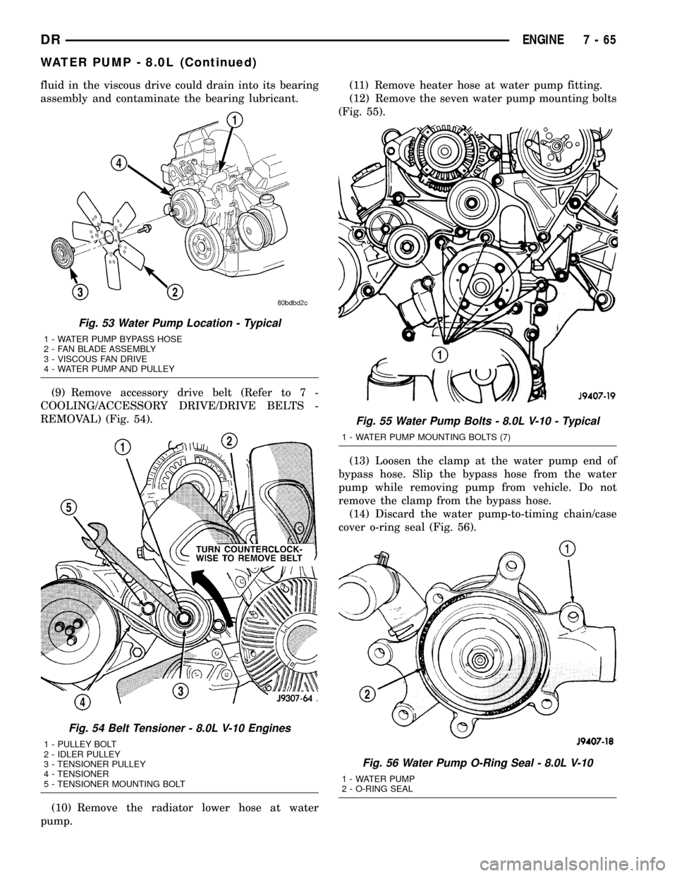
fluid in the viscous drive could drain into its bearing
assembly and contaminate the bearing lubricant.
(9) Remove accessory drive belt (Refer to 7 -
COOLING/ACCESSORY DRIVE/DRIVE BELTS -
REMOVAL) (Fig. 54).
(10) Remove the radiator lower hose at water
pump.(11) Remove heater hose at water pump fitting.
(12) Remove the seven water pump mounting bolts
(Fig. 55).
(13) Loosen the clamp at the water pump end of
bypass hose. Slip the bypass hose from the water
pump while removing pump from vehicle. Do not
remove the clamp from the bypass hose.
(14) Discard the water pump-to-timing chain/case
cover o-ring seal (Fig. 56).
Fig. 53 Water Pump Location - Typical
1 - WATER PUMP BYPASS HOSE
2 - FAN BLADE ASSEMBLY
3 - VISCOUS FAN DRIVE
4 - WATER PUMP AND PULLEY
Fig. 54 Belt Tensioner - 8.0L V-10 Engines
1 - PULLEY BOLT
2 - IDLER PULLEY
3 - TENSIONER PULLEY
4 - TENSIONER
5 - TENSIONER MOUNTING BOLT
Fig. 55 Water Pump Bolts - 8.0L V-10 - Typical
1 - WATER PUMP MOUNTING BOLTS (7)
Fig. 56 Water Pump O-Ring Seal - 8.0L V-10
1 - WATER PUMP
2 - O-RING SEAL
DRENGINE 7 - 65
WATER PUMP - 8.0L (Continued)
Page 381 of 2627

(15) Remove the heater hose fitting from water
pump if pump replacement is necessary. Note posi-
tion (direction) of fitting before removal. Fitting must
be re-installed to same position.
CAUTION: Do not pry the water pump at timing
chain case/cover. The machined surfaces may be
damaged resulting in leaks.
CLEANING
Clean gasket mating surfaces as necessary.
INSPECTION
Visually inspect the water pump and replace if it
has any of the following conditions:
²The body is cracked or damaged
²Water leaks from the shaft seal. This is evident
by traces of coolant below the vent hole
²Loose or rough turning bearing. Also inspect
thermal fan drive
²Impeller rubbing the pump body
INSTALLATION
(1) If water pump is being replaced, install the
heater hose fitting to the pump. Tighten fitting to 16
N´m (144 in. lbs.) torque. After fitting has been
torqued, position fitting as shown in (Fig. 57). When
positioning fitting, do not back off (rotate counter-
clockwise). Use a sealant on the fitting such as
MopartThread Sealant With Teflon. Refer to the
directions on the package.
CAUTION: This heater hose fitting must be installed
to pump before pump is installed to engine.
(2) Clean the o-ring mating surfaces at rear of
water pump and front of timing chain/case cover.
(3) Apply a small amount of petroleum jelly to
o-ring (Fig. 56). This will help retain o-ring to water
pump.
(4) Install water pump to engine as follows: Guide
water pump fitting into bypass hose as pump is being
installed. Install water pump bolts (Fig. 55). Tighten
water pump mounting bolts to 40 N´m (30 ft. lbs.)
torque.
(5) Position bypass hose clamp to bypass hose.
(6) Spin water pump to be sure that pump impel-
ler does not rub against timing chain case/cover.
(7) Connect radiator lower hose to water pump.
(8) Connect heater hose and hose clamp to heater
hose fitting.
(9) Install drive belt (Refer to 7 - COOLING/AC-
CESSORY DRIVE/DRIVE BELTS - INSTALLA-
TION).
(10) Position fan shroud and fan blade/viscous fan
drive assembly to vehicle as a complete unit.(11) Install fan shroud to radiator. Tighten bolts to
6 N´m (50 in. lbs.) torque.
(12) Install fan blade/viscous fan drive assembly to
water pump shaft.
(13) Fill cooling system (Refer to 7 - COOLING -
STANDARD PROCEDURE).
(14) Connect negative battery cable.
(15) Start and warm the engine. Check for leaks.
Fig. 57 Heater Hose Fitting Position - 8.0L V-10
1 - HEATER HOSE FITTING
2 - WATER PUMP
7 - 66 ENGINEDR
WATER PUMP - 8.0L (Continued)
Page 382 of 2627

TRANSMISSION
TABLE OF CONTENTS
page page
TRANS COOLER
DESCRIPTION.........................67
OPERATION...........................67
REMOVAL.............................68
INSTALLATION.........................68
TRANS COOLER - 5.9L DIESEL
DESCRIPTION.........................68
OPERATION...........................69REMOVAL
REMOVAL - AIR TO OIL COOLER.........69
REMOVAL - WATER TO OIL COOLER......69
DISASSEMBLY - 5.9L DIESEL ONLY.........70
ASSEMBLY - 5.9L DIESEL ONLY...........70
INSTALLATION
INSTALLATION - AIR TO OIL COOLER.....70
INSTALLATION - WATER-TO-AIR COOLER . . 70
TRANS COOLER
DESCRIPTION
An air-to-oil transmission oil cooler is standard on
all engine packages. The transmission oil cooler is
mounted to the front of the radiator above the power
steering cooler (Fig. 1) and (Fig. 2)
OPERATION
Transmission oil is routed through the cooler
where heat is removed from the transmission oil
before returning to the transmission.
Fig. 1 Cooling Module - 3.7L/4.7L/5.7L
1 - TRANS OIL COOLER
2 - LOCATING TABS
3 - POWER STEERING OIL COOLER
4 - POWER STEERING OIL COOLER MOUNTING BOLT
5 - TRANS OIL COOLER OUTLET
6 - TRANS OIL COOLER INLET
7 - COOLER LINE CLIP
8 - COOLER LINE CLIP
9 - MOUNTING BOLT
10 - RADIATOR
Fig. 2 COOLING MODULE - 5.9L GAS
1 - TRANS OIL COOLER BYPASS (5.9L only)
2 - OIL COOLER THERMOSTATIC BYPASS VALVE (5.9L only)
3 -TRANS OIL COOLER
4 - OIL COOLER MOUNTING BOLT (4)
5 - POWER STEERING COOLER
6 - POWER STEERING COOLER MOUNTING BOLT(2)
7 - TRANS OIL COOLER OUTLET
8 - TRANS OIL COOLER INLET
9 - COOLER LINE CLIP
10 - COOLER LINE CLIP
11 - RADIATOR
DRTRANSMISSION 7 - 67
Page 383 of 2627
REMOVAL
(1) Disconnect the battery negative cable.
(2) Place a drain pan under the oil cooler lines.
(3) Disconnect the transmission oil cooler line
quick-connect fitting at the cooler outlet using the
quick connect release tool 6935. Plug the cooler lines
to prevent oil leakage.
(4) Unsnap the transmission cooler tubes from the
radiator tank clips.
(5) Remove the bolt attaching the transmission
cooler to the radiator.
(6) Remove oil cooler from the vehicle. Take care
not to damage the radiator core or transmission
cooler tubes.
INSTALLATION
(1) Position the transmission cooler tubes to the
front of the radiator by sliding brackets into slots on
radiator inlet tank.
(2) Snap the transmission cooler tubes into the
clips on the side of the radiator tank.
(3) Install the transmission cooler attaching bolt.
Tighten the bolt to 16 N´m (140 in. lbs.).
(4) Inspect the quick connect fittings for debris
and install the quick connect fitting on the cooler
tube until an audible ªclickº is heard. Pull apart the
connection to verify proper installation and install
the secondary latches.
(5) Connect the battery negative cable.
(6) Start the engine and check all fittings for
leaks.
(7) Check the fluid level in the automatic trans-
mission. Refer to the appropriate transmission sec-
tion(Refer to 21 - TRANSMISSION/TRANSAXLE/
AUTOMATIC - 45RFE/545RFE/FLUID - STANDARD
PROCEDURE) or(Refer to 21 - TRANSMISSION/
TRANSAXLE/AUTOMATIC - 46RE/FLUID - STAN-
DARD PROCEDURE).
TRANS COOLER - 5.9L DIESEL
DESCRIPTION
All diesel models equipped with an automatic
transmission are equipped with both a main water-
to-oil cooler and a separate air-to-oil cooler. Both cool-
ers are supplied as standard equipment on diesel
engine powered models when equipped with an auto-
matic transmission.
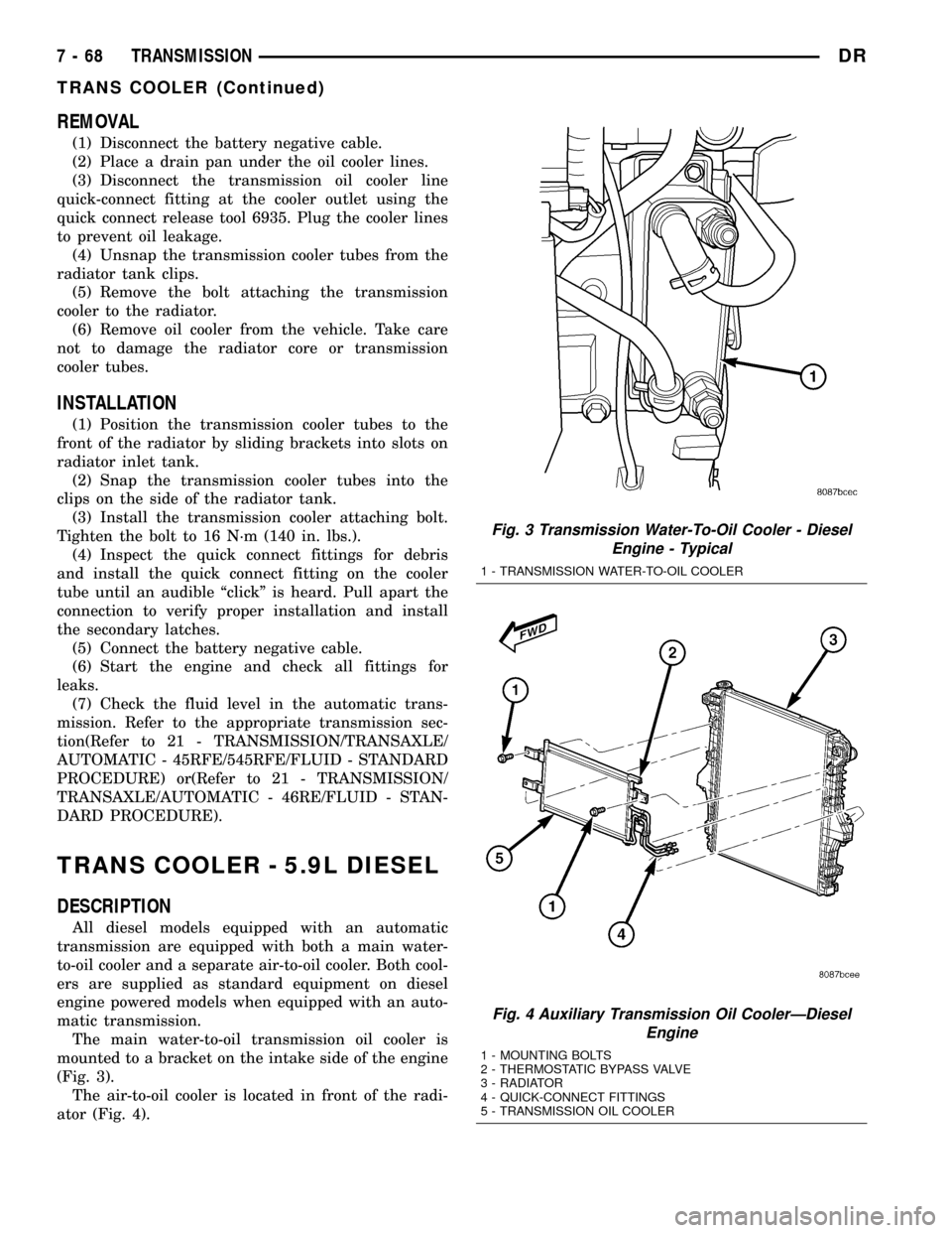
The main water-to-oil transmission oil cooler is
mounted to a bracket on the intake side of the engine
(Fig. 3).
The air-to-oil cooler is located in front of the radi-
ator (Fig. 4).
Fig. 3 Transmission Water-To-Oil Cooler - Diesel
Engine - Typical
1 - TRANSMISSION WATER-TO-OIL COOLER
Fig. 4 Auxiliary Transmission Oil CoolerÐDiesel
Engine
1 - MOUNTING BOLTS
2 - THERMOSTATIC BYPASS VALVE
3 - RADIATOR
4 - QUICK-CONNECT FITTINGS
5 - TRANSMISSION OIL COOLER
7 - 68 TRANSMISSIONDR
TRANS COOLER (Continued)
Page 384 of 2627
OPERATION
The transmission oil is routed through the main
cooler first, then the auxiliary cooler where addi-
tional heat is removed from the transmission oil
before returning to the transmission. The auxiliary
cooler has an internal thermostat that controls fluid
flow through the cooler. When the transmission fluid
is cold (less then operating temperature), the fluid is
routed through the cooler bypass. When the trans-
mission fluid reaches operating temperatures and
above, the thermostat closes off the bypass allowing
fluid flow through the cooler. The thermostat is ser-
vicable.
REMOVAL
REMOVAL - AIR TO OIL COOLER
(1) Remove Charge Air Cooler (Refer to 11 -
EXHAUST SYSTEM/TURBOCHARGER SYSTEM/
CHARGE AIR COOLER AND PLUMBING -
REMOVAL).
(2) Place a drain pan under the oil cooler.
(3) Raise the vehicle.
(4) Disconnect the oil cooler quick-connect fittings
from the transmission lines.
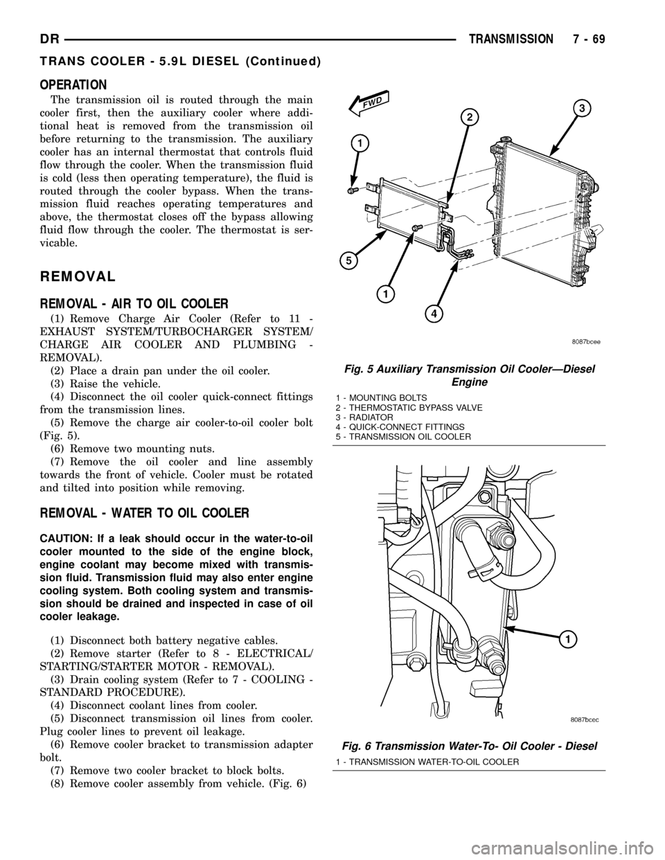
(5) Remove the charge air cooler-to-oil cooler bolt
(Fig. 5).
(6) Remove two mounting nuts.
(7) Remove the oil cooler and line assembly
towards the front of vehicle. Cooler must be rotated
and tilted into position while removing.
REMOVAL - WATER TO OIL COOLER
CAUTION: If a leak should occur in the water-to-oil
cooler mounted to the side of the engine block,
engine coolant may become mixed with transmis-
sion fluid. Transmission fluid may also enter engine
cooling system. Both cooling system and transmis-
sion should be drained and inspected in case of oil
cooler leakage.
(1) Disconnect both battery negative cables.
(2) Remove starter (Refer to 8 - ELECTRICAL/
STARTING/STARTER MOTOR - REMOVAL).
(3) Drain cooling system (Refer to 7 - COOLING -
STANDARD PROCEDURE).
(4) Disconnect coolant lines from cooler.
(5) Disconnect transmission oil lines from cooler.
Plug cooler lines to prevent oil leakage.
(6) Remove cooler bracket to transmission adapter
bolt.
(7) Remove two cooler bracket to block bolts.
(8) Remove cooler assembly from vehicle. (Fig. 6)
Fig. 5 Auxiliary Transmission Oil CoolerÐDiesel
Engine
1 - MOUNTING BOLTS
2 - THERMOSTATIC BYPASS VALVE
3 - RADIATOR
4 - QUICK-CONNECT FITTINGS
5 - TRANSMISSION OIL COOLER
Fig. 6 Transmission Water-To- Oil Cooler - Diesel
1 - TRANSMISSION WATER-TO-OIL COOLER
DRTRANSMISSION 7 - 69
TRANS COOLER - 5.9L DIESEL (Continued)
Page 385 of 2627

DISASSEMBLY - 5.9L DIESEL ONLY
NOTE: The transmission oil cooler uses an internal
thermostat to control transmission oil flow through
the cooler. This thermostat is servicable.
(1) Remove the transmission oil cooler (Refer to 7 -
COOLING/TRANSMISSION/TRANS COOLER -
REMOVAL).
(2) Remove the snap ring retaining the thermostat
end plug (Fig. 7).
(3) Remove the end plug, thermostat and spring
from transmission oil cooler (Fig. 7).
ASSEMBLY - 5.9L DIESEL ONLY
(1) Throughly clean the thermostat bore on the
transmission oil cooler.
(2) Install the new spring, thermostat, end plug
and snap ring.
(3) Install the transmission oil cooler (Refer to 7 -
COOLING/TRANSMISSION/TRANS COOLER -
INSTALLATION).
INSTALLATION
INSTALLATION - AIR TO OIL COOLER
(1) Carefully position the oil cooler assembly to the
vehicle.
(2) Install two nuts and one bolt. Tighten to 11
N´m (95 in. lbs.) torque.
(3) Connect the quick-connect fittings to the trans-
mission cooler lines.
(4) Install Charge Air Cooler (Refer to 11 -
EXHAUST SYSTEM/TURBOCHARGER SYSTEM/
CHARGE AIR COOLER AND PLUMBING -
INSTALLATION).
(5) Start the engine and check all fittings for
leaks.
(6) Check the fluid level in the automatic trans-
mission (Refer to 21 - TRANSMISSION/TRANS-
AXLE/AUTOMATIC - 47RE/FLUID - STANDARD
PROCEDURE).
INSTALLATION - WATER-TO-AIR COOLER
(1) Position oil cooler on cylinder block.
(2) Install lower mounting bolt to cooler at the cyl-
inder block. Torque bolt to 77 N´m (57 ft. lbs.)
(3) Install upper mounting bolt at the cylinder
block. Torque bolt to 24 N´m (19 ft. lbs.)
(4) Install cooler bracket to transmission adapter
bolt. Tighten to 24 N´m (18 ft. lbs.).
(5) Connect transmission oil lines to cooler.
(6) Connect coolant hoses to cooler.
(7) Install starter motor (Refer to 8 - ELECTRI-
CAL/STARTING/STARTER MOTOR - INSTALLA-
TION).
(8) Connect battery negative cables.
(9) Fill cooling system (Refer to 7 - COOLING -
STANDARD PROCEDURE).
(10) Check transmission oil level and fill as neces-
sary (Refer to 21 - TRANSMISSION/TRANSAXLE/
AUTOMATIC - 47RE/FLUID - STANDARD
PROCEDURE).
Fig. 7 Transmission Oil Cooler Thermostat
Removal/Installation
1 - THERMOSTAT HOUSING
2 - SPRING
3 - END PLUG
4 - SNAP RING
5 - THERMOSTAT
7 - 70 TRANSMISSIONDR
TRANS COOLER - 5.9L DIESEL (Continued)
Page 390 of 2627

NOTE: This model has a two-piece antenna coaxial
cable. Tests 2 and 4 must be conducted in two
steps to isolate an antenna cable problem. First,
test the primary antenna cable (integral to the
antenna body and cable) from the coaxial cable
connector behind the right side kick panel to the
antenna body. Then, test the secondary antenna
cable (instrument panel antenna cable) from the
coaxial cable connector behind the right side kick
panel to the coaxial cable connector at the radio.
TEST 1
Test 1 determines if the antenna mast is insulated
from ground. Proceed as follows:
(1) Disconnect and isolate the antenna coaxial
cable connector behind the right side kick panel.
(2) Touch one ohmmeter test lead to the tip of the
antenna mast. Touch the other test lead to known
ground. Check the ohmmeter reading for continuity.
(3) There should be no continuity. If OK, go to Test
2. If not OK, replace the faulty antenna body and
cable.
TEST 2
Test 2 checks the antenna conductor components
for an open circuit. This test should be performed
first on the entire antenna circuit, from the antenna
mast to the center conductor of the coaxial cable con-
nector at the radio. If an open circuit is detected,
each of the three antenna conductor components
(antenna mast, antenna body and cable, instrument
panel antenna cable) should be isolated and tested
individually to locate the exact component that is the
source of the open circuit. To begin this test, proceed
as follows:(1) Disconnect the instrument panel antenna cable
coaxial connector from the back of the radio.
(2) Touch one ohmmeter test lead to the tip of the
antenna mast. Touch the other test lead to the center
conductor pin of the instrument panel antenna cable
coaxial connector for the radio. Check the ohmmeter
reading for continuity.
(3) There should be continuity. The ohmmeter
should register only a fraction of an ohm resistance.
High or infinite resistance indicates a damaged or
open antenna conductor. If OK, go to Test 3. If not
OK, isolate and test each of the individual antenna
conductor components. Replace only the faulty
antenna conductor component.
TEST 3
Test 3 checks the condition of the vehicle body
ground connection. To begin this test, proceed as fol-
lows:
(1) This test must be performed with the battery
positive cable disconnected from the battery. Discon-
nect and isolate both battery cables, negative cable
first.
(2) Reconnect the battery negative cable.
(3) Touch one ohmmeter test lead to a good clean
ground point on the vehicle fender. Touch the other
test lead to the battery negative terminal post. Check
the ohmmeter reading for continuity.
(4) There should be continuity. The ohmmeter
should register less than one ohm resistance. High or
infinite resistance indicates a loose, corroded, or
damaged connection between the battery negative
terminal and the vehicle body. If OK, go to Test 4. If
not OK, check the battery negative cable connection
to the vehicle body and the radio noise suppression
ground strap connections to the engine and the vehi-
cle body for being loose or corroded. Clean or tighten
these connections as required.
TEST 4
Test 4 checks the condition of the connection
between the antenna coaxial cable shield and the
vehicle body ground as follows:
(1) Disconnect and isolate the antenna coaxial
cable connector behind the right side kick panel.
(2) Touch one ohmmeter test lead to a good clean
ground point on the vehicle fender. Touch the other
test lead to the outer crimp on the antenna coaxial
cable connector. Check the ohmmeter reading for con-
tinuity.
(3) There should be continuity. The ohmmeter
should register less than one ohm resistance. High or
infinite resistance indicates a loose, corroded, or
damaged connection between the antenna body and
the vehicle body or between the antenna body and
the antenna coaxial cable shield. If not OK, clean the
Fig. 2 Antenna Tests - Typical
DRAUDIO/VIDEO 8A - 5
ANTENNA BODY & CABLE (Continued)
Page 394 of 2627

RADIO NOISE SUPPRESSION
GROUND STRAP
DESCRIPTION
Radio noise suppression devices are factory-in-
stalled standard equipment on this vehicle. Radio
Frequency Interference (RFI) and ElectroMagnetic
Interference (EMI) can be produced by any on-board
or external source of electromagnetic energy. These
electromagnetic energy sources can radiate electro-
magnetic signals through the air, or conduct them
through the vehicle electrical system.
When the audio system converts RFI or EMI to an
audible acoustic wave form, it is referred to as radio
noise. This undesirable radio noise is generally man-
ifested in the form of ªbuzzing,º ªhissing,º ªpopping,º
ªclicking,º ªcrackling,º and/or ªwhirringº sounds. In
most cases, RFI and EMI radio noise can be sup-
pressed using a combination of vehicle and compo-
nent grounding, filtering and shielding techniques.
This vehicle is equipped with factory-installed radio
noise suppression devices that were designed to min-
imize exposure to typical sources of RFI and EMI;
thereby, minimizing radio noise complaints.
Factory-installed radio noise suppression is accom-
plished primarily through circuitry or devices that
are integral to the factory-installed radios, audio
power amplifiers and other on-board electrical com-
ponents such as generators, wiper motors, blower
motors, and fuel pumps that have been found to be
potential sources of RFI or EMI. External radio noise
suppression devices that are used on this vehicle to
control RFI or EMI, and can be serviced, include the
following:
²Engine-to-body ground strap- This length of
braided ground strap has an eyelet terminal connec-
tor crimped to each end. One end is secured to the
engine cylinder head(s). The other is secured to the
plenum at the exhaust heat shield forward/outer
attaching stud.
²Resistor-type spark plugs- This type of spark
plug has an internal resistor connected in series
between the spark plug terminal and the center elec-
trode to help reduce the production of electromag-
netic radiation that can result in radio noise.
OPERATION
There are two common strategies that can be used
to suppress Radio Frequency Interference (RFI) and
ElectroMagnetic Interference (EMI) radio noise. The
first suppression strategy involves preventing the
production of RFI and EMI electromagnetic signals
at their sources. The second suppression strategy
involves preventing the reception of RFI and EMIelectromagnetic signals by the audio system compo-
nents.
The use of braided ground straps in key locations
is part of the RFI and EMI prevention strategy.
These ground straps ensure adequate ground paths,
particularly for high current components such as
many of those found in the starting, charging, igni-
tion, engine control and transmission control sys-
tems. An insufficient ground path for any of these
high current components may result in radio noise
caused by induced voltages created as the high cur-
rent seeks alternative ground paths through compo-
nents or circuits intended for use by, or in close
proximity to the audio system components or circuits.
Preventing the reception of RFI and EMI is accom-
plished by ensuring that the audio system compo-
nents are correctly installed in the vehicle. Loose,
corroded or improperly soldered wire harness connec-
tions, improperly routed wiring and inadequate audio
system component grounding can all contribute to
the reception of RFI and EMI. A properly grounded
antenna body and radio chassis, as well as a shielded
antenna coaxial cable with clean and tight connec-
tions will each help reduce the potential for reception
of RFI and EMI.
REMOVAL
BED TO CAB
(1) Disconnect and isolate the battery negative
cable.
(2) Remove the attaching bolts and strap (Fig. 10).
Fig. 10 BED TO CAB GROUND STRAP
1 - BED
2 - CAB
3 - GROUND STRAP
4 - MOUNTING BOLTS
DRAUDIO/VIDEO 8A - 9
Page 395 of 2627
ENGINE TO HEAT SHIELD - 3.7L ENGINE
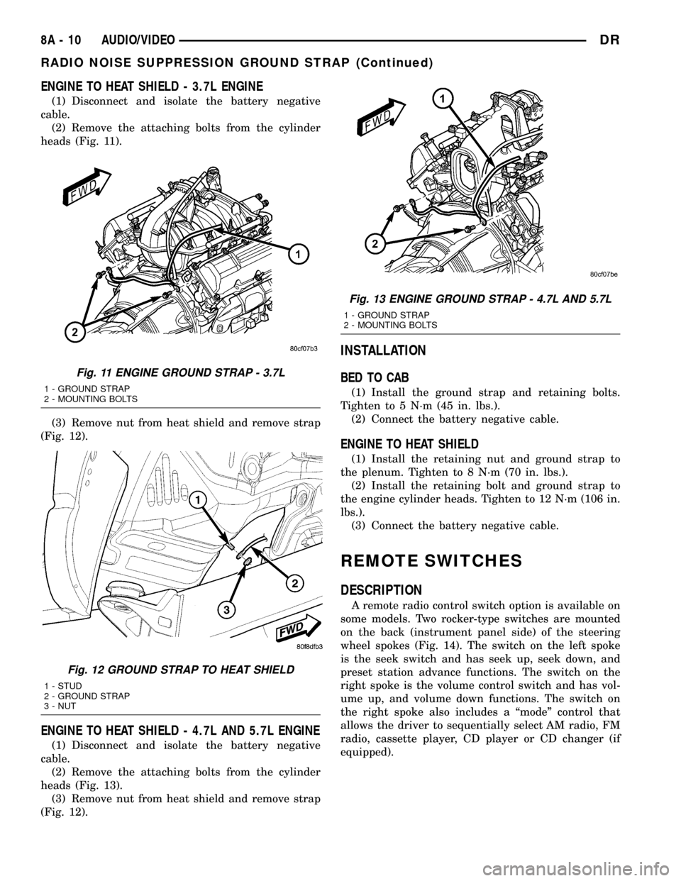
(1) Disconnect and isolate the battery negative
cable.
(2) Remove the attaching bolts from the cylinder
heads (Fig. 11).
(3) Remove nut from heat shield and remove strap
(Fig. 12).
ENGINE TO HEAT SHIELD - 4.7L AND 5.7L ENGINE
(1) Disconnect and isolate the battery negative
cable.
(2) Remove the attaching bolts from the cylinder
heads (Fig. 13).
(3) Remove nut from heat shield and remove strap
(Fig. 12).
INSTALLATION
BED TO CAB
(1) Install the ground strap and retaining bolts.
Tighten to 5 N´m (45 in. lbs.).
(2) Connect the battery negative cable.
ENGINE TO HEAT SHIELD
(1) Install the retaining nut and ground strap to
the plenum. Tighten to 8 N´m (70 in. lbs.).
(2) Install the retaining bolt and ground strap to
the engine cylinder heads. Tighten to 12 N´m (106 in.
lbs.).
(3) Connect the battery negative cable.
REMOTE SWITCHES
DESCRIPTION
A remote radio control switch option is available on
some models. Two rocker-type switches are mounted
on the back (instrument panel side) of the steering
wheel spokes (Fig. 14). The switch on the left spoke
is the seek switch and has seek up, seek down, and
preset station advance functions. The switch on the
right spoke is the volume control switch and has vol-
ume up, and volume down functions. The switch on
the right spoke also includes a ªmodeº control that
allows the driver to sequentially select AM radio, FM
radio, cassette player, CD player or CD changer (if
equipped).
Fig. 11 ENGINE GROUND STRAP - 3.7L
1 - GROUND STRAP
2 - MOUNTING BOLTS
Fig. 12 GROUND STRAP TO HEAT SHIELD
1 - STUD
2 - GROUND STRAP
3 - NUT
Fig. 13 ENGINE GROUND STRAP - 4.7L AND 5.7L
1 - GROUND STRAP
2 - MOUNTING BOLTS
8A - 10 AUDIO/VIDEODR
RADIO NOISE SUPPRESSION GROUND STRAP (Continued)
Page 402 of 2627
CHIME/BUZZER
TABLE OF CONTENTS
page page
CHIME WARNING SYSTEM
DESCRIPTION..........................1
OPERATION............................1DIAGNOSIS AND TESTING - CHIME
WARNING SYSTEM.....................3
CHIME WARNING SYSTEM
DESCRIPTION
A chime warning system is standard factory-in-
stalled equipment on this model. The chime warning
system uses a single chime tone generator that is
integral to the instrument cluster to provide an audi-
ble indication of various vehicle conditions that may
require the attention of the vehicle operator. The
chime warning system includes the following major
components, which are described in further detail
elsewhere in this service information:
²Door Ajar Switch- A door ajar switch is inte-
gral to each door latch. This switch provides an input
to the chime warning system indicating whether the
front doors are open or closed.
²Ignition Switch- A key-in ignition switch is
integral to the ignition switch. The key-in ignition
switch provides an input to the chime warning sys-
tem indicating whether a key is present in the igni-
tion lock cylinder.
²Instrument Cluster- The instrument cluster
contains an integral chime tone generator, integrated
circuitry, a central processing unit and the program-
ming to provide all of the proper chime warning sys-
tem features based upon the monitored inputs. The
instrument cluster circuitry monitors hard-wired
switch inputs, as well as message inputs received
from other vehicle electronic modules on the Pro-
grammable Communications Interface (PCI) data bus
network.
²Headlamp Switch- The headlamp switch pro-
vides an input to the chime warning system indicat-
ing when the exterior lamps are turned On or Off.
²Seat Belt Switch- A seat belt switch is inte-
gral to the driver seat belt buckle-half unit. The seat
belt switch provides an input to the chime warning
system indicating whether the driver seat belt is fas-
tened.
Hard wired circuitry connects many of the chime
warning system components to each other through
the electrical system of the vehicle. These hard wired
circuits are integral to several wire harnesses, which
are routed throughout the vehicle and retained bymany different methods. Refer to the appropriate
wiring information.
The instrument cluster chime warning system cir-
cuitry and the integral chime tone generator cannot
be adjusted or repaired. If the instrument cluster or
the chime tone generator are damaged or faulty, the
instrument cluster must be replaced.
OPERATION
The chime warning system is designed to provide
an audible output as an indication of various condi-
tions that may require the attention or awareness of
the vehicle operator. The chime warning system com-
ponents operate on battery voltage received through
the Ignition-Off Draw (IOD) fuse in the Power Distri-
bution Center (PDC) so that the system may operate
regardless of the ignition switch position.
The chime warning system provides an audible
warning to the vehicle operator under the following
conditions:
²Air Bag Warning- The instrument cluster
chime tone generator will generate a single chime
tone when the airbag indicator is illuminated for an
airbag system fault condition. The instrument cluster
uses airbag indicator lamp-on and lamp-off message
inputs received from the Airbag Control Module
(ACM) over the Programmable Communications
Interface (PCI) data bus indicating that the airbag
indicator should be illuminated for an airbag system
fault condition.
²Door Ajar Warning- The instrument cluster
chime tone generator will generate a single chimes to
announce that the hard wired inputs from the door
ajar switches and the ignition switch as well as an
engine speed message input received from the PCM
over the PCI data bus indicate that a driver or pas-
senger door is opened with the ignition switch in the
On position and vehicle speed present.
²Engine Coolant Temperature High Warning
(Diesel Engine Only)- The instrument cluster
chime tone generator will generate a single chime
tone when the check gauges indicator is illuminated
for a high or critical engine coolant temperature con-
dition. The instrument cluster uses engine coolant
temperature message inputs received from the diesel
DRCHIME/BUZZER 8B - 1