Front lamp DODGE RAM 1500 1998 2.G Workshop Manual
[x] Cancel search | Manufacturer: DODGE, Model Year: 1998, Model line: RAM 1500, Model: DODGE RAM 1500 1998 2.GPages: 2627
Page 1545 of 2627
FRONT AIR DAM
REMOVAL
(1) Remove the two outboard screws.
(2) Remove the three middle screws and remove
the air dam.
INSTALLATION
(1) Position the air dam onto the bumper and seat
the carrot type fasteners fully.
(2) Starting at the center screw install the three
middle screws.
(3) Install the two outboard screws.
FRONT BUMPER
REMOVAL
(1) Using a grease pencil or equivalent, mark the
position of the bumper on the frame rail tip to aid
installation.
(2) Disconnect the fog lamp electrical connector at
the left frame rail.
(3) Support the bumper with a suitable lifting
device.
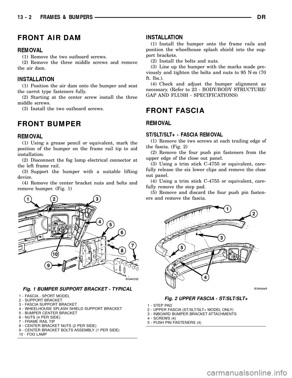
(4) Remove the center bracket nuts and bolts and
remove bumper. (Fig. 1)
INSTALLATION
(1) Install the bumper onto the frame rails and
position the wheelhouse splash shield into the sup-
port brackets.
(2) Install the bolts and nuts.
(3) Line up the bumper with the marks made pre-
viously and tighten the bolts and nuts to 95 N´m (70
ft. lbs.).
(4) Check and adjust the bumper alignment as
necessary. (Refer to 23 - BODY/BODY STRUCTURE/
GAP AND FLUSH - SPECIFICATIONS)
FRONT FASCIA
REMOVAL
ST/SLT/SLT+ - FASCIA REMOVAL
(1) Remove the two screws at each trailing edge of
the fascia. (Fig. 2)
(2) Remove the four push pin fasteners from the
upper edge of the close out panel.
(3) Using a trim stick C-4755 or equivalent, care-
fully release the six lower clips and remove the close
out panel.
(4) Using a trim stick C-4755 or equivalent, care-
fully remove the step pad.
(5) Remove and discard the four push pin fasten-
ers and remove the fascia.
Fig. 1 BUMPER SUPPORT BRACKET - TYPICAL
1 - FASCIA - SPORT MODEL
2 - SUPPORT BRACKET
3 - FASCIA SUPPORT BRACKET
4 - WHEELHOUSE SPLASH SHIELD SUPPORT BRACKET
5 - BUMPER CENTER BRACKET
6 - NUTS (4 PER SIDE)
7 - FRAME RAIL TIP
8 - CENTER BRACKET NUTS (2 PER SIDE)
9 - CENTER BRACKET BOLTS ASSEMBLY (1 PER SIDE)
10 - FOG LAMPFig. 2 UPPER FASCIA - ST/SLT/SLT+
1 - STEP PAD
2 - UPPER FASCIA (ST/SLT/SLT+ MODEL ONLY)
3 - INBOARD BUMPER BRACKET ATTACHMENTS
4 - SCREWS (4)
5 - PUSH PIN FASTENERS (4)
13 - 2 FRAMES & BUMPERSDR
Page 1554 of 2627
STANDARD PROCEDURE - HYDROFORM
FENDER RAIL REPAIR
CAUTION: This repair procedure assumes damage
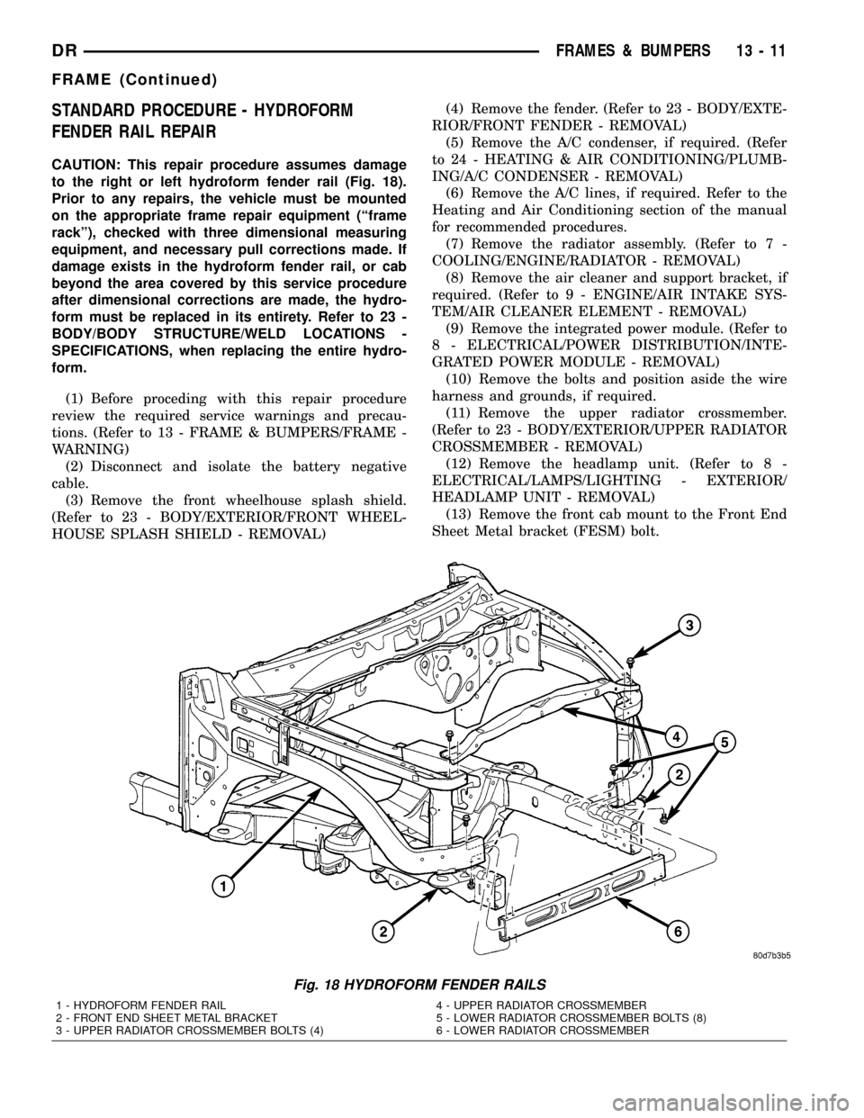
to the right or left hydroform fender rail (Fig. 18).
Prior to any repairs, the vehicle must be mounted
on the appropriate frame repair equipment (ªframe
rackº), checked with three dimensional measuring
equipment, and necessary pull corrections made. If
damage exists in the hydroform fender rail, or cab
beyond the area covered by this service procedure
after dimensional corrections are made, the hydro-
form must be replaced in its entirety. Refer to 23 -
BODY/BODY STRUCTURE/WELD LOCATIONS -
SPECIFICATIONS, when replacing the entire hydro-
form.
(1) Before proceding with this repair procedure
review the required service warnings and precau-
tions. (Refer to 13 - FRAME & BUMPERS/FRAME -
WARNING)
(2) Disconnect and isolate the battery negative
cable.
(3) Remove the front wheelhouse splash shield.
(Refer to 23 - BODY/EXTERIOR/FRONT WHEEL-
HOUSE SPLASH SHIELD - REMOVAL)(4) Remove the fender. (Refer to 23 - BODY/EXTE-
RIOR/FRONT FENDER - REMOVAL)
(5) Remove the A/C condenser, if required. (Refer
to 24 - HEATING & AIR CONDITIONING/PLUMB-
ING/A/C CONDENSER - REMOVAL)
(6) Remove the A/C lines, if required. Refer to the
Heating and Air Conditioning section of the manual
for recommended procedures.
(7) Remove the radiator assembly. (Refer to 7 -
COOLING/ENGINE/RADIATOR - REMOVAL)
(8) Remove the air cleaner and support bracket, if
required. (Refer to 9 - ENGINE/AIR INTAKE SYS-
TEM/AIR CLEANER ELEMENT - REMOVAL)
(9) Remove the integrated power module. (Refer to
8 - ELECTRICAL/POWER DISTRIBUTION/INTE-
GRATED POWER MODULE - REMOVAL)
(10) Remove the bolts and position aside the wire
harness and grounds, if required.
(11) Remove the upper radiator crossmember.
(Refer to 23 - BODY/EXTERIOR/UPPER RADIATOR
CROSSMEMBER - REMOVAL)
(12) Remove the headlamp unit. (Refer to 8 -
ELECTRICAL/LAMPS/LIGHTING - EXTERIOR/
HEADLAMP UNIT - REMOVAL)
(13) Remove the front cab mount to the Front End
Sheet Metal bracket (FESM) bolt.
Fig. 18 HYDROFORM FENDER RAILS
1 - HYDROFORM FENDER RAIL
2 - FRONT END SHEET METAL BRACKET
3 - UPPER RADIATOR CROSSMEMBER BOLTS (4)4 - UPPER RADIATOR CROSSMEMBER
5 - LOWER RADIATOR CROSSMEMBER BOLTS (8)
6 - LOWER RADIATOR CROSSMEMBER
DRFRAMES & BUMPERS 13 - 11
FRAME (Continued)
Page 1555 of 2627
(14) Remove the bolts attaching the lower radiator
crossmember to the hydroform fender rail. (Fig. 18)
CAUTION: Do not use any flame or plasma cutting
equipment to cut the frame in this procedure. The
inaccurate and high temperatures achieved during
flame or plasma cutting will change the metal char-
acteristics and may weaken the frame and/or repair
location.
(15) Using a reciprocating saw or equivalent, cut
the fender rail and shotgun at a straight and square
section of the hydroform and remove.
(16) Smooth and square the cut edges.
(17) Using the damaged structure as a reference
cut the service part at the same location as the first
cut. Smooth and square the cut edges.
NOTE: The repair structure should butt up to the
remaining structure and provide the same overall
vehicle geometry.
(18) Fabricate 51 mm (2.0 in.) long repair inserts
using scrap from the old structure or the replacement
part. It will be necessary to split the inserts on each
of their four sides to fit into the hydroform.
(19) Remove any paint or e-coat from the inserts
and also to the interior and exterior of the hydro-
forms.
(20) Cut plug weld holes as described below.
²On the upper rail, cut one 13 mm (0.5 in.) hole
on each side of the rail, 25 mm (1.0 in.) from the butt
joint of the tubes.
²On the lower rail, cut one 13 mm (0.5 in.) hole
on the top and bottom sides of the rail 25 mm (1.0
in.) from the butt joint of the tube.
²On the lower rail, cut two 13 mm (0.5 in.) holes
on the inner and outer sides of the rail 25 mm (1.0
in.) from the butt joint of the tube.
CAUTION: Shield the surrounding area and compo-
nents from exposure to the welding spatter and
heat.
(21) Install the insert 1º into the replacement part
and tack into place with a weld. (Refer to 13 -
FRAME & BUMPERS/FRAME - SPECIFICATIONS -
WELDING)
(22) Insert the service part into place and using
the appropriate measuring equipment, verify the
front end sheet metal bracket's location in all three
(X,Y, and Z) planes of space. (Fig. 19)
(23) Complete all 360É plug welds.
NOTE: Before the final welding, use three dimen-
sional measuring equipment to ensure the part is in
the correct location. Verify that tap plate extrusion
at the bottom of the vertical post lines up with theisolator and hole in the frame perch mount. Also
ensure the lower radiator closure tube is bolted into
the forward shotgun ends.
(24) Complete welding by making a 360É butt weld
around the fender rails.
(25) Metal finish the exposed welds on the hydro-
forms.
(26) Dress the welded area and apply corrosion
resistant coatings inside and out.
(a) Inside the rail, inject a creeping wax based
rust inhibitor compound to the inside of the hydro-
forms ensuring 100% coverage including the mat-
ing face between the fender rail sections and insert
such that corrosion protection is restored in the
internal cavity.
(b) Apply a durable top coat to the outside of the
repair area.
(27) Install the front cab mount bolt if previously
removed and tighten to 81 N´m (60 ft. lbs.).
(28) Install the lower radiator crossmember bolts
and tighten to 28 N´m (21 ft. lbs.).
(29) Install the headlamp unit. (Refer to 8 - ELEC-
TRICAL/LAMPS/LIGHTING - EXTERIOR/HEAD-
LAMP UNIT - INSTALLATION)
(30) Install the upper radiator crossmember. (Refer
to 23 - BODY/EXTERIOR/UPPER RADIATOR
CROSSMEMBER - INSTALLATION)
(31) Install the wire harness and ground if previ-
ously removed and install the bolts.
(32) Install the integrated power module, if previ-
ously removed. (Refer to 8 - ELECTRICAL/POWER
DISTRIBUTION/INTEGRATED POWER MODULE -
INSTALLATION)
(33) Install the air cleaner bracket and air cleaner,
if previously removed. (Refer to 9 - ENGINE/AIR
INTAKE SYSTEM/AIR CLEANER ELEMENT -
INSTALLATION)
(34) Install the radiator assembly. (Refer to 7 -
COOLING/ENGINE/RADIATOR - INSTALLATION)
(35) Install the A/C lines, if previously removed.
Refer to the Heating and Air Conditioning section of
the manual for the recommended procedures.
(36) Install the A/C condenser, if previously
removed. (Refer to 24 - HEATING & AIR CONDI-
TIONING/PLUMBING/A/C CONDENSER - INSTAL-
LATION)
(37) Install the fender. (Refer to 23 - BODY/EXTE-
RIOR/FRONT FENDER - INSTALLATION)
(38) Install the front wheelhouse splash shield.
(Refer to 23 - BODY/EXTERIOR/FRONT WHEEL-
HOUSE SPLASH SHIELD - INSTALLATION)
(39) Reconnect the battery ground.
13 - 12 FRAMES & BUMPERSDR
FRAME (Continued)
Page 1582 of 2627
REMOVAL
3.7L V-6
WARNING: THE FUEL SYSTEM IS UNDER CON-
STANT PRESSURE EVEN WITH ENGINE OFF.
BEFORE SERVICING FUEL RAIL, FUEL SYSTEM
PRESSURE MUST BE RELEASED.
CAUTION: The left and right fuel rails are replaced
as an assembly. Do not attempt to separate rail
halves at connector tubes (Fig. 18). Due to design
of tubes, it does not use any clamps. Never attempt
to install a clamping device of any kind to tubes.
When removing fuel rail assembly for any reason,
be careful not to bend or kink tubes.
(1) Remove fuel tank filler tube cap.
(2) Perform Fuel System Pressure Release Proce-
dure.
(3) Remove negative battery cable at battery.
(4) Remove air duct at throttle body air box.
(5) Remove air box at throttle body.
(6) Remove air resonator mounting bracket at
front of throttle body (2 bolts).
(7) Disconnect fuel line latch clip and fuel line at
fuel rail. A special tool will be necessary for fuel line
disconnection. Refer to Quick-Connect Fittings.
(8) Remove necessary vacuum lines at throttle
body.
(9) Disconnect electrical connectors at all 6 fuel
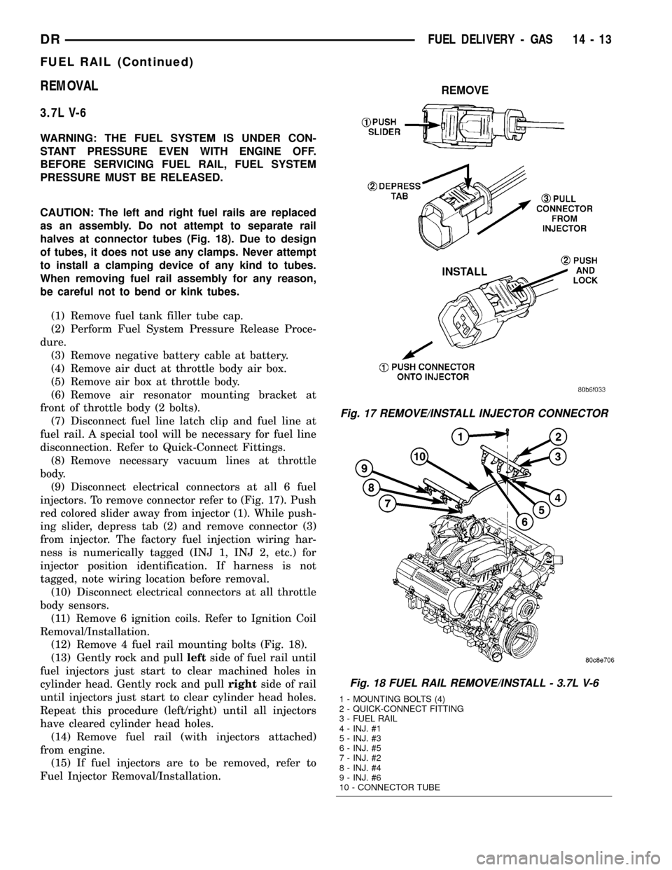
injectors. To remove connector refer to (Fig. 17). Push
red colored slider away from injector (1). While push-
ing slider, depress tab (2) and remove connector (3)
from injector. The factory fuel injection wiring har-
ness is numerically tagged (INJ 1, INJ 2, etc.) for
injector position identification. If harness is not
tagged, note wiring location before removal.
(10) Disconnect electrical connectors at all throttle
body sensors.
(11) Remove 6 ignition coils. Refer to Ignition Coil
Removal/Installation.
(12) Remove 4 fuel rail mounting bolts (Fig. 18).
(13) Gently rock and pullleftside of fuel rail until
fuel injectors just start to clear machined holes in
cylinder head. Gently rock and pullrightside of rail
until injectors just start to clear cylinder head holes.
Repeat this procedure (left/right) until all injectors
have cleared cylinder head holes.
(14) Remove fuel rail (with injectors attached)
from engine.
(15) If fuel injectors are to be removed, refer to
Fuel Injector Removal/Installation.
Fig. 17 REMOVE/INSTALL INJECTOR CONNECTOR
Fig. 18 FUEL RAIL REMOVE/INSTALL - 3.7L V-6
1 - MOUNTING BOLTS (4)
2 - QUICK-CONNECT FITTING
3 - FUEL RAIL
4 - INJ. #1
5 - INJ. #3
6 - INJ. #5
7 - INJ. #2
8 - INJ. #4
9 - INJ. #6
10 - CONNECTOR TUBE
DRFUEL DELIVERY - GAS 14 - 13
FUEL RAIL (Continued)
Page 1583 of 2627
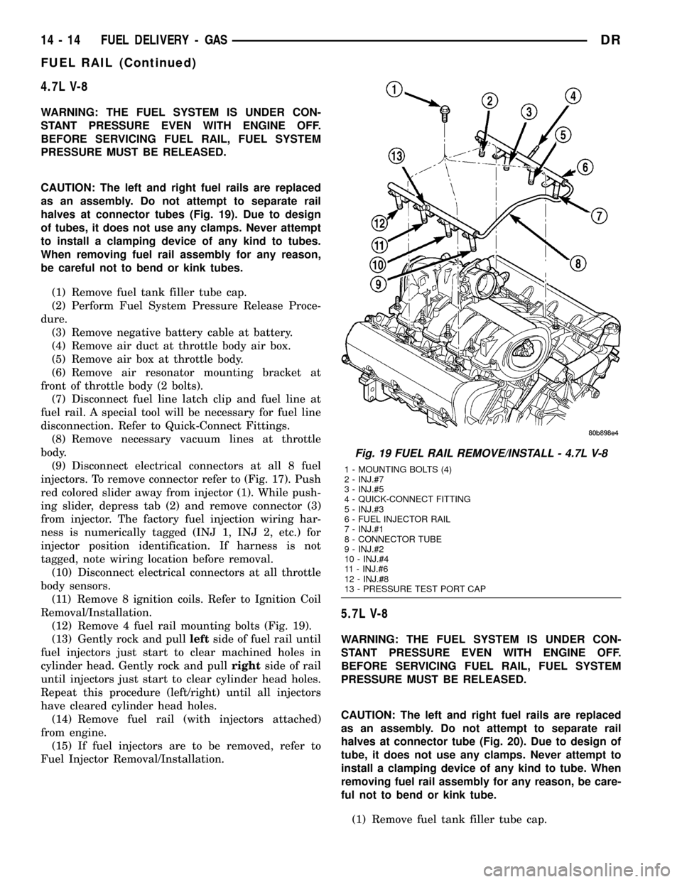
4.7L V-8
WARNING: THE FUEL SYSTEM IS UNDER CON-
STANT PRESSURE EVEN WITH ENGINE OFF.
BEFORE SERVICING FUEL RAIL, FUEL SYSTEM
PRESSURE MUST BE RELEASED.
CAUTION: The left and right fuel rails are replaced
as an assembly. Do not attempt to separate rail
halves at connector tubes (Fig. 19). Due to design
of tubes, it does not use any clamps. Never attempt
to install a clamping device of any kind to tubes.
When removing fuel rail assembly for any reason,
be careful not to bend or kink tubes.
(1) Remove fuel tank filler tube cap.
(2) Perform Fuel System Pressure Release Proce-
dure.
(3) Remove negative battery cable at battery.
(4) Remove air duct at throttle body air box.
(5) Remove air box at throttle body.
(6) Remove air resonator mounting bracket at
front of throttle body (2 bolts).
(7) Disconnect fuel line latch clip and fuel line at
fuel rail. A special tool will be necessary for fuel line
disconnection. Refer to Quick-Connect Fittings.
(8) Remove necessary vacuum lines at throttle
body.
(9) Disconnect electrical connectors at all 8 fuel
injectors. To remove connector refer to (Fig. 17). Push
red colored slider away from injector (1). While push-
ing slider, depress tab (2) and remove connector (3)
from injector. The factory fuel injection wiring har-
ness is numerically tagged (INJ 1, INJ 2, etc.) for
injector position identification. If harness is not
tagged, note wiring location before removal.
(10) Disconnect electrical connectors at all throttle
body sensors.
(11) Remove 8 ignition coils. Refer to Ignition Coil
Removal/Installation.
(12) Remove 4 fuel rail mounting bolts (Fig. 19).
(13) Gently rock and pullleftside of fuel rail until
fuel injectors just start to clear machined holes in
cylinder head. Gently rock and pullrightside of rail
until injectors just start to clear cylinder head holes.
Repeat this procedure (left/right) until all injectors
have cleared cylinder head holes.
(14) Remove fuel rail (with injectors attached)
from engine.
(15) If fuel injectors are to be removed, refer to
Fuel Injector Removal/Installation.
5.7L V-8
WARNING: THE FUEL SYSTEM IS UNDER CON-
STANT PRESSURE EVEN WITH ENGINE OFF.
BEFORE SERVICING FUEL RAIL, FUEL SYSTEM
PRESSURE MUST BE RELEASED.
CAUTION: The left and right fuel rails are replaced
as an assembly. Do not attempt to separate rail
halves at connector tube (Fig. 20). Due to design of
tube, it does not use any clamps. Never attempt to
install a clamping device of any kind to tube. When
removing fuel rail assembly for any reason, be care-
ful not to bend or kink tube.
(1) Remove fuel tank filler tube cap.
Fig. 19 FUEL RAIL REMOVE/INSTALL - 4.7L V-8
1 - MOUNTING BOLTS (4)
2 - INJ.#7
3 - INJ.#5
4 - QUICK-CONNECT FITTING
5 - INJ.#3
6 - FUEL INJECTOR RAIL
7 - INJ.#1
8 - CONNECTOR TUBE
9 - INJ.#2
10 - INJ.#4
11 - INJ.#6
12 - INJ.#8
13 - PRESSURE TEST PORT CAP
14 - 14 FUEL DELIVERY - GASDR
FUEL RAIL (Continued)
Page 1625 of 2627
This will ensure proper gear-to-shaft tighten-
ing.
(5) Clean pump gear and pump shaft at machined
tapers with an evaporative type cleaner such as
brake cleaner.
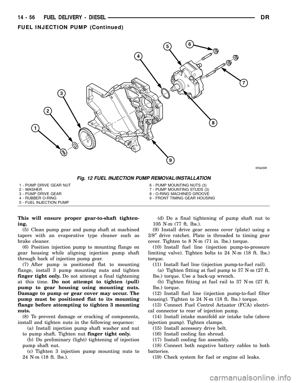
(6) Position injection pump to mounting flange on
gear housing while aligning injection pump shaft
through back of injection pump gear.
(7) After pump is positioned flat to mounting
flange, install 3 pump mounting nuts and tighten
finger tight only.Do not attempt a final tightening
at this time.Do not attempt to tighten (pull)
pump to gear housing using mounting nuts.
Damage to pump or gear cover may occur. The
pump must be positioned flat to its mounting
flange before attempting to tighten 3 mounting
nuts.
(8) To prevent damage or cracking of components,
install and tighten nuts in the following sequence:
(a) Install injection pump shaft washer and nut
to pump shaft. Tighten nutfinger tight only.
(b) Do preliminary (light) tightening of injection
pump shaft nut.
(c) Tighten 3 injection pump mounting nuts to
24 N´m (18 ft. lbs.).(d) Do a final tightening of pump shaft nut to
105 N´m (77 ft. lbs.).
(9) Install drive gear access cover (plate) using a
3/8º drive ratchet. Plate is threaded to timing gear
cover. Tighten to 8 N´m (71 in. lbs.) torque.
(10) Install fuel line (injection pump-to-pressure
limiting valve). Tighten bolts to 24 N´m (18 ft. lbs.)
torque.
(11) Install fuel line (injection pump-to-fuel rail).
(a) Tighten fitting at fuel pump to 37 N´m (27 ft.
lbs.) torque. Use a back-up wrench.
(b) Tighten fitting at fuel rail to 37 N´m (27 ft.
lbs.) torque.
(12) Install fuel line (injection pump-to-fuel filter
housing). Tighten to 24 N´m (18 ft. lbs.) torque.
(13) Connect Fuel Control Actuator (FCA) electri-
cal connector to rear of injection pump.
(14) Install intake manifold air intake tube (above
injection pump). Tighten clamps.
(15) Install accessory drive belt.
(16) Install cooling fan shroud.
(17) Install cooling fan assembly.
(18) Connect both negative battery cables to both
batteries.
(19) Check system for fuel or engine oil leaks.
Fig. 12 FUEL INJECTION PUMP REMOVAL/INSTALLATION
1 - PUMP DRIVE GEAR NUT
2 - WASHER
3 - PUMP DRIVE GEAR
4 - RUBBER O-RING
5 - FUEL INJECTION PUMP6 - PUMP MOUNTING NUTS (3)
7 - PUMP MOUNTING STUDS (3)
8 - O-RING MACHINED GROOVE
9 - FRONT TIMING GEAR HOUSING
14 - 56 FUEL DELIVERY - DIESELDR
FUEL INJECTION PUMP (Continued)
Page 1689 of 2627
LINKAGE - LINK/COIL
TABLE OF CONTENTS
page page
LINKAGE - LINK/COIL
DESCRIPTION.........................34
STANDARD PROCEDURE - LUBRICATION....34
SPECIFICATIONS
TORQUE CHART......................35
SPECIAL TOOLS
STEERING LINKAGE...................35
DAMPER
REMOVAL.............................36
INSTALLATION.........................36
DRAG LINK
REMOVAL.............................36INSTALLATION.........................36
PITMAN ARM
REMOVAL.............................36
INSTALLATION.........................37
TIE ROD END
REMOVAL.............................37
INSTALLATION.........................37
TRACK BAR
REMOVAL.............................38
INSTALLATION.........................38
LINKAGE - LINK/COIL
DESCRIPTION
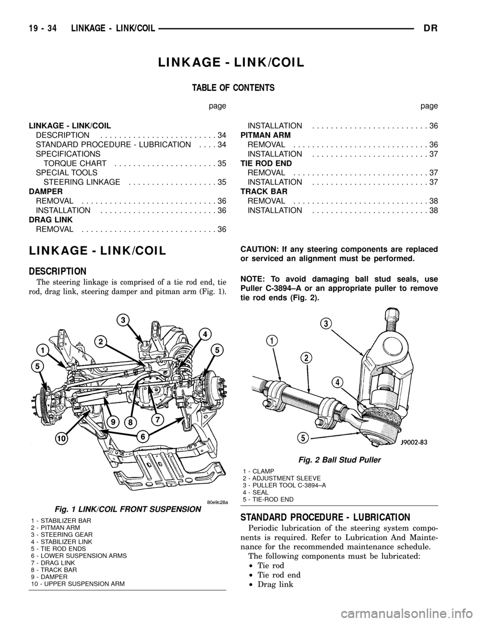
The steering linkage is comprised of a tie rod end, tie
rod, drag link, steering damper and pitman arm (Fig. 1).
CAUTION: If any steering components are replaced
or serviced an alignment must be performed.
NOTE: To avoid damaging ball stud seals, use
Puller C-3894±A or an appropriate puller to remove
tie rod ends (Fig. 2).
STANDARD PROCEDURE - LUBRICATION
Periodic lubrication of the steering system compo-
nents is required. Refer to Lubrication And Mainte-
nance for the recommended maintenance schedule.
The following components must be lubricated:
²Tie rod
²Tie rod end
²Drag link
Fig. 1 LINK/COIL FRONT SUSPENSION
1 - STABILIZER BAR
2 - PITMAN ARM
3 - STEERING GEAR
4 - STABILIZER LINK
5 - TIE ROD ENDS
6 - LOWER SUSPENSION ARMS
7 - DRAG LINK
8 - TRACK BAR
9 - DAMPER
10 - UPPER SUSPENSION ARM
Fig. 2 Ball Stud Puller
1 - CLAMP
2 - ADJUSTMENT SLEEVE
3 - PULLER TOOL C-3894±A
4 - SEAL
5 - TIE-ROD END
19 - 34 LINKAGE - LINK/COILDR
Page 1778 of 2627
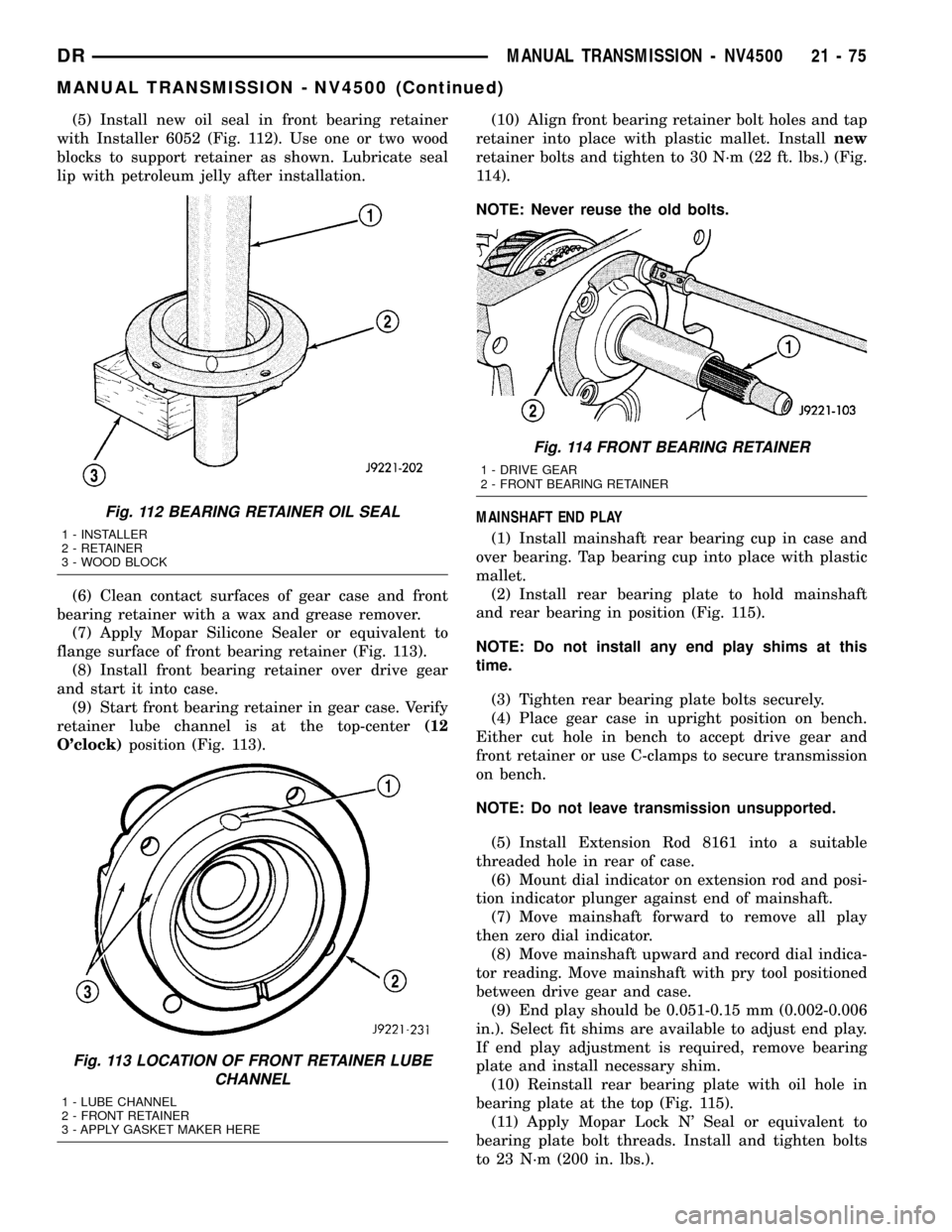
(5) Install new oil seal in front bearing retainer
with Installer 6052 (Fig. 112). Use one or two wood
blocks to support retainer as shown. Lubricate seal
lip with petroleum jelly after installation.
(6) Clean contact surfaces of gear case and front
bearing retainer with a wax and grease remover.
(7) Apply Mopar Silicone Sealer or equivalent to
flange surface of front bearing retainer (Fig. 113).
(8) Install front bearing retainer over drive gear
and start it into case.
(9) Start front bearing retainer in gear case. Verify
retainer lube channel is at the top-center(12
O'clock)position (Fig. 113).(10) Align front bearing retainer bolt holes and tap
retainer into place with plastic mallet. Installnew
retainer bolts and tighten to 30 N´m (22 ft. lbs.) (Fig.
114).
NOTE: Never reuse the old bolts.
MAINSHAFT END PLAY
(1) Install mainshaft rear bearing cup in case and
over bearing. Tap bearing cup into place with plastic
mallet.
(2) Install rear bearing plate to hold mainshaft
and rear bearing in position (Fig. 115).
NOTE: Do not install any end play shims at this
time.
(3) Tighten rear bearing plate bolts securely.
(4) Place gear case in upright position on bench.
Either cut hole in bench to accept drive gear and
front retainer or use C-clamps to secure transmission
on bench.
NOTE: Do not leave transmission unsupported.
(5) Install Extension Rod 8161 into a suitable
threaded hole in rear of case.
(6) Mount dial indicator on extension rod and posi-
tion indicator plunger against end of mainshaft.
(7) Move mainshaft forward to remove all play
then zero dial indicator.
(8) Move mainshaft upward and record dial indica-
tor reading. Move mainshaft with pry tool positioned
between drive gear and case.
(9) End play should be 0.051-0.15 mm (0.002-0.006
in.). Select fit shims are available to adjust end play.
If end play adjustment is required, remove bearing
plate and install necessary shim.
(10) Reinstall rear bearing plate with oil hole in
bearing plate at the top (Fig. 115).
(11) Apply Mopar Lock N' Seal or equivalent to
bearing plate bolt threads. Install and tighten bolts
to 23 N´m (200 in. lbs.).
Fig. 112 BEARING RETAINER OIL SEAL
1 - INSTALLER
2 - RETAINER
3 - WOOD BLOCK
Fig. 113 LOCATION OF FRONT RETAINER LUBE
CHANNEL
1 - LUBE CHANNEL
2 - FRONT RETAINER
3 - APPLY GASKET MAKER HERE
Fig. 114 FRONT BEARING RETAINER
1 - DRIVE GEAR
2 - FRONT BEARING RETAINER
DRMANUAL TRANSMISSION - NV4500 21 - 75
MANUAL TRANSMISSION - NV4500 (Continued)
Page 1784 of 2627
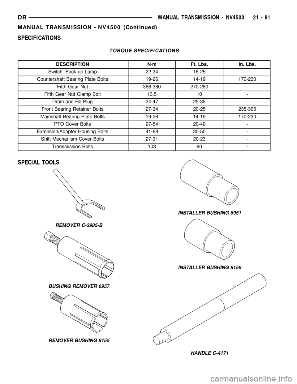
SPECIFICATIONS
TORQUE SPECIFICATIONS
DESCRIPTION N´m Ft. Lbs. In. Lbs.
Switch, Back-up Lamp 22-34 16-25 -
Countershaft Bearing Plate Bolts 19-26 14-19 170-230
Fifth Gear Nut 366-380 270-280 -
Fifth Gear Nut Clamp Bolt 13.5 10 -
Drain and Fill Plug 34-47 25-35 -
Front Bearing Retainer Bolts 27-34 20-25 235-305
Mainshaft Bearing Plate Bolts 19-26 14-19 170-230
PTO Cover Bolts 27-54 20-40 -
Extension/Adapter Housing Bolts 41-68 30-50 -
Shift Mechanism Cover Bolts 27-31 20-23 -
Transmission Bolts 108 80 -
SPECIAL TOOLS
REMOVER C-3985-B
BUSHING REMOVER 6957
REMOVER BUSHING 8155
INSTALLER BUSHING 6951
INSTALLER BUSHING 8156
HANDLE C-4171
DRMANUAL TRANSMISSION - NV4500 21 - 81
MANUAL TRANSMISSION - NV4500 (Continued)
Page 1855 of 2627
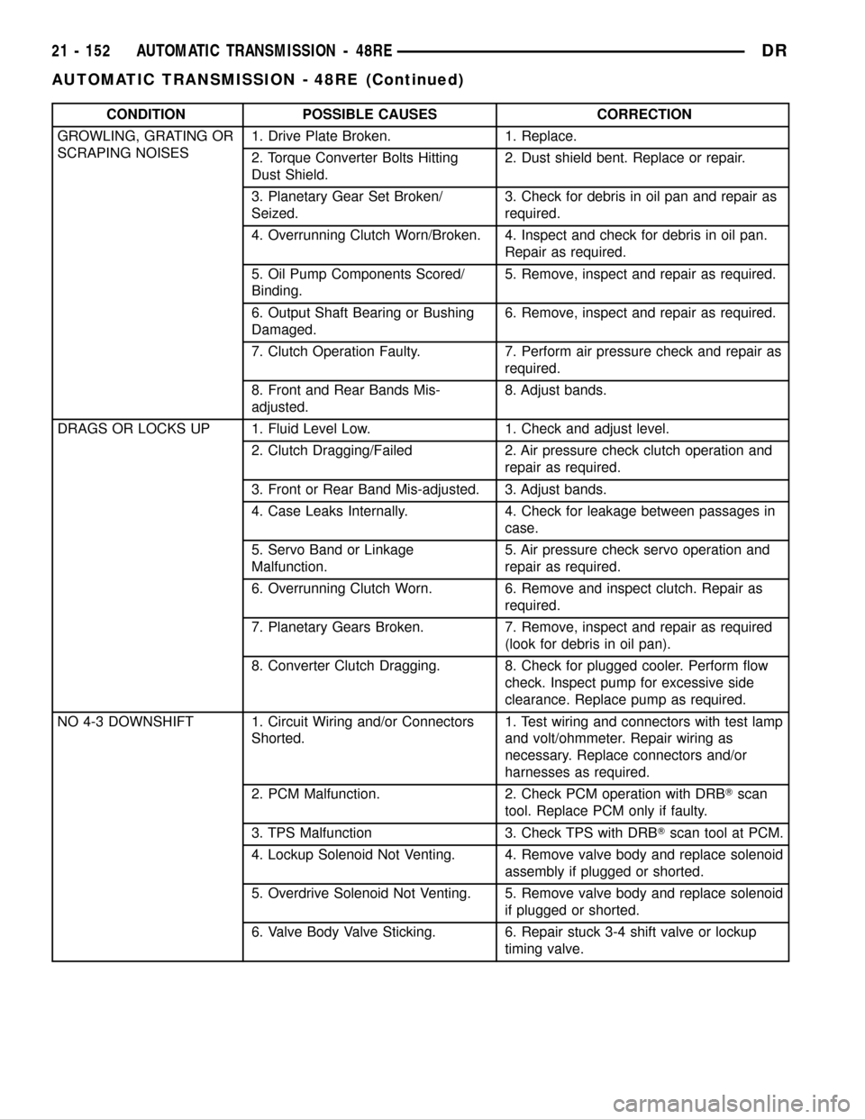
CONDITION POSSIBLE CAUSES CORRECTION
GROWLING, GRATING OR
SCRAPING NOISES1. Drive Plate Broken. 1. Replace.
2. Torque Converter Bolts Hitting
Dust Shield.2. Dust shield bent. Replace or repair.
3. Planetary Gear Set Broken/
Seized.3. Check for debris in oil pan and repair as
required.
4. Overrunning Clutch Worn/Broken. 4. Inspect and check for debris in oil pan.
Repair as required.
5. Oil Pump Components Scored/
Binding.5. Remove, inspect and repair as required.
6. Output Shaft Bearing or Bushing
Damaged.6. Remove, inspect and repair as required.
7. Clutch Operation Faulty. 7. Perform air pressure check and repair as
required.
8. Front and Rear Bands Mis-
adjusted.8. Adjust bands.
DRAGS OR LOCKS UP 1. Fluid Level Low. 1. Check and adjust level.
2. Clutch Dragging/Failed 2. Air pressure check clutch operation and
repair as required.
3. Front or Rear Band Mis-adjusted. 3. Adjust bands.
4. Case Leaks Internally. 4. Check for leakage between passages in
case.
5. Servo Band or Linkage
Malfunction.5. Air pressure check servo operation and
repair as required.
6. Overrunning Clutch Worn. 6. Remove and inspect clutch. Repair as
required.
7. Planetary Gears Broken. 7. Remove, inspect and repair as required
(look for debris in oil pan).
8. Converter Clutch Dragging. 8. Check for plugged cooler. Perform flow
check. Inspect pump for excessive side
clearance. Replace pump as required.
NO 4-3 DOWNSHIFT 1. Circuit Wiring and/or Connectors
Shorted.1. Test wiring and connectors with test lamp
and volt/ohmmeter. Repair wiring as
necessary. Replace connectors and/or
harnesses as required.
2. PCM Malfunction. 2. Check PCM operation with DRBTscan
tool. Replace PCM only if faulty.
3. TPS Malfunction 3. Check TPS with DRBTscan tool at PCM.
4. Lockup Solenoid Not Venting. 4. Remove valve body and replace solenoid
assembly if plugged or shorted.
5. Overdrive Solenoid Not Venting. 5. Remove valve body and replace solenoid
if plugged or shorted.
6. Valve Body Valve Sticking. 6. Repair stuck 3-4 shift valve or lockup
timing valve.
21 - 152 AUTOMATIC TRANSMISSION - 48REDR
AUTOMATIC TRANSMISSION - 48RE (Continued)