700 DODGE RAM 1500 1998 2.G User Guide
[x] Cancel search | Manufacturer: DODGE, Model Year: 1998, Model line: RAM 1500, Model: DODGE RAM 1500 1998 2.GPages: 2627
Page 1243 of 2627

Bore Size Indicator C-119
Oil Pressure Gauge C-3292
Piston Ring Compressor C-385
Pressure Tester Kit 7700
Bloc±Chek±Kit C-3685±A
ENGINE SUPPORT FIXTURE 8534
9 - 20 ENGINE - 3.7LDR
ENGINE - 3.7L (Continued)
Page 1245 of 2627

²Excessive steam (white smoke) emitting from
exhaust
²Coolant foaming
CYLINDER-TO-CYLINDER LEAKAGE TEST
To determine if an engine cylinder head gasket is
leaking between adjacent cylinders, follow the proce-
dures in Cylinder Compression Pressure Test (Refer
to 9 - ENGINE - DIAGNOSIS AND TESTING). An
engine cylinder head gasket leaking between adja-
cent cylinders will result in approximately a 50 - 70%
reduction in compression pressure.
CYLINDER-TO-WATER JACKET LEAKAGE TEST
WARNING: USE EXTREME CAUTION WHEN THE
ENGINE IS OPERATING WITH COOLANT PRES-
SURE CAP REMOVED.
VISUAL TEST METHOD
With the engine cool, remove the coolant pressure
cap. Start the engine and allow it to warm up until
thermostat opens.
If a large combustion/compression pressure leak
exists, bubbles will be visible in the coolant.
COOLING SYSTEM TESTER METHOD
WARNING: WITH COOLING SYSTEM TESTER IN
PLACE, PRESSURE WILL BUILD UP FAST. EXCES-
SIVE PRESSURE BUILT UP, BY CONTINUOUS
ENGINE OPERATION, MUST BE RELEASED TO A
SAFE PRESSURE POINT. NEVER PERMIT PRES-
SURE TO EXCEED 138 kPa (20 psi).
Install Cooling System Tester 7700 or equivalent to
pressure cap neck. Start the engine and observe the
tester's pressure gauge. If gauge pulsates with every
power stroke of a cylinder a combustion pressure
leak is evident.
CHEMICAL TEST METHOD
Combustion leaks into the cooling system can also
be checked by using Bloc-Chek Kit C-3685-A or
equivalent. Perform test following the procedures
supplied with the tool kit.
REMOVAL
(1) Disconnect the negative cable from the battery.
(2) Raise the vehicle on a hoist.
(3) Disconnect the exhaust pipe at the left side
exhaust manifold.
(4) Drain the engine coolant(Refer to 7 - COOL-
ING - STANDARD PROCEDURE).
(5) Lower the vehicle.(6) Remove the intake manifold(Refer to 9 -
ENGINE/MANIFOLDS/INTAKE MANIFOLD -
REMOVAL).
(7) Remove the master cylinder and booster assem-
bly(Refer to 5 - BRAKES/HYDRAULIC/MECHANI-
CAL/POWER BRAKE BOOSTER - REMOVAL).
(8) Remove the cylinder head cover(Refer to 9 -
ENGINE/CYLINDER HEAD/CYLINDER HEAD
COVER(S) - REMOVAL).
(9) Remove the fan shroud and fan blade assem-
bly(Refer to 7 - COOLING/ENGINE/RADIATOR FAN
- REMOVAL).
(10) Remove accessory drive belt(Refer to 7 -
COOLING/ACCESSORY DRIVE/DRIVE BELTS -
REMOVAL).
(11) Remove the power steering pump and set
aside.
(12) Rotate the crankshaft until the damper tim-
ing mark is aligned with TDC indicator mark (Fig.
5).
(13) Verify the V6 mark on the camshaft sprocket
is at the 12 o'clock position (Fig. 6). Rotate the crank-
shaft one turn if necessary.
(14) Remove the crankshaft damper(Refer to 9 -
ENGINE/ENGINE BLOCK/VIBRATION DAMPER -
REMOVAL).
(15) Remove the timing chain cover(Refer to 9 -
ENGINE/VALVE TIMING/TIMING BELT / CHAIN
COVER(S) - REMOVAL).
Fig. 5 Engine Top Dead Center
1 - TIMING CHAIN COVER
2 - CRANKSHAFT TIMING MARKS
9 - 22 ENGINE - 3.7LDR
CYLINDER HEAD - LEFT (Continued)
Page 1273 of 2627
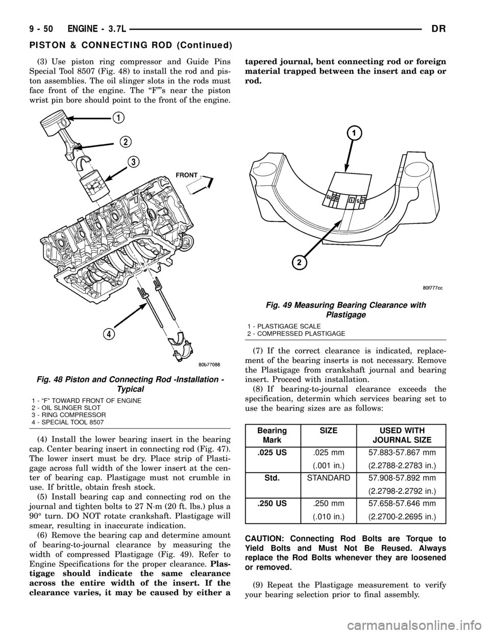
(3) Use piston ring compressor and Guide Pins
Special Tool 8507 (Fig. 48) to install the rod and pis-
ton assemblies. The oil slinger slots in the rods must
face front of the engine. The ªFº's near the piston
wrist pin bore should point to the front of the engine.
(4) Install the lower bearing insert in the bearing
cap. Center bearing insert in connecting rod (Fig. 47).
The lower insert must be dry. Place strip of Plasti-
gage across full width of the lower insert at the cen-
ter of bearing cap. Plastigage must not crumble in
use. If brittle, obtain fresh stock.
(5) Install bearing cap and connecting rod on the
journal and tighten bolts to 27 N´m (20 ft. lbs.) plus a
90É turn. DO NOT rotate crankshaft. Plastigage will
smear, resulting in inaccurate indication.
(6) Remove the bearing cap and determine amount
of bearing-to-journal clearance by measuring the
width of compressed Plastigage (Fig. 49). Refer to
Engine Specifications for the proper clearance.Plas-
tigage should indicate the same clearance
across the entire width of the insert. If the
clearance varies, it may be caused by either atapered journal, bent connecting rod or foreign
material trapped between the insert and cap or
rod.
(7) If the correct clearance is indicated, replace-
ment of the bearing inserts is not necessary. Remove
the Plastigage from crankshaft journal and bearing
insert. Proceed with installation.
(8) If bearing-to-journal clearance exceeds the
specification, determin which services bearing set to
use the bearing sizes are as follows:
Bearing
MarkSIZE USED WITH
JOURNAL SIZE
.025 US.025 mm 57.883-57.867 mm
(.001 in.) (2.2788-2.2783 in.)
Std.STANDARD 57.908-57.892 mm
(2.2798-2.2792 in.)
.250 US.250 mm 57.658-57.646 mm
(.010 in.) (2.2700-2.2695 in.)
CAUTION: Connecting Rod Bolts are Torque to
Yield Bolts and Must Not Be Reused. Always
replace the Rod Bolts whenever they are loosened
or removed.
(9) Repeat the Plastigage measurement to verify
your bearing selection prior to final assembly.
Fig. 48 Piston and Connecting Rod -Installation -
Typical
1 - ªFº TOWARD FRONT OF ENGINE
2 - OIL SLINGER SLOT
3 - RING COMPRESSOR
4 - SPECIAL TOOL 8507
Fig. 49 Measuring Bearing Clearance with
Plastigage
1 - PLASTIGAGE SCALE
2 - COMPRESSED PLASTIGAGE
9 - 50 ENGINE - 3.7LDR
PISTON & CONNECTING ROD (Continued)
Page 1329 of 2627

Oil Pressure Gauge C-3292
Piston Ring Compressor C-385
Pressure Tester Kit 7700
Bloc±Chek±Kit C-3685±A
ENGINE SUPPORT FIXTURE 8534
9 - 106 ENGINE - 4.7LDR
ENGINE - 4.7L (Continued)
Page 1420 of 2627

Dial Indicator C-3339
Handle C-4171
Oil Pressure Gauge C-3292
Piston Ring Compressor C-385
Pressure Tester Kit 7700
Rear Crankshaft Seal Installer 8349
Rear Crankshaft Seal Remover 8506
Valve Spring Compressor C-3422-B
Valve Spring Tester C-647
DRENGINE - 5.7L 9 - 197
ENGINE - 5.7L (Continued)
Page 1423 of 2627

þ Loss of engine power
þ Engine misfiring
þ Poor fuel economy
²Possible indications of the cylinder head gasket
leaking between a cylinder and an adjacent water
jacket are:
þ Engine overheating
þ Loss of coolant
þ Excessive steam (white smoke) emitting from
exhaust
þ Coolant foaming
CYLINDER-TO-CYLINDER LEAKAGE TEST
To determine if an engine cylinder head gasket is
leaking between adjacent cylinders, follow the proce-
dures in Cylinder Compression Pressure Test in this
section. An engine cylinder head gasket leaking
between adjacent cylinders will result in approxi-
mately a 50±70% reduction in compression pressure.
CYLINDER-TO-WATER JACKET LEAKAGE TEST
WARNING: USE EXTREME CAUTION WHEN THE
ENGINE IS OPERATING WITH COOLANT PRES-
SURE CAP REMOVED.
VISUAL TEST METHOD
With the engine cool, remove the coolant pressure
cap. Start the engine and allow it to warm up until
thermostat opens.
If a large combustion/compression pressure leak
exists, bubbles will be visible in the coolant.
COOLING SYSTEM TESTER METHOD
WARNING: WITH COOLING SYSTEM TESTER IN
PLACE, PRESSURE WILL BUILD UP FAST. EXCES-
SIVE PRESSURE BUILT UP, BY CONTINUOUS
ENGINE OPERATION, MUST BE RELEASED TO A
SAFE PRESSURE POINT. NEVER PERMIT PRES-
SURE TO EXCEED 138 kPa (20 psi).
Install Cooling System Tester 7700 or equivalent to
pressure cap neck. Start the engine and observe the
tester's pressure gauge. If gauge pulsates with every
power stroke of a cylinder a combustion pressure
leak is evident.
CHEMICAL TEST METHOD
Combustion leaks into the cooling system can also
be checked by using Bloc-Chek Kit C-3685-A or
equivalent. Perform test following the procedures
supplied with the tool kit.
REMOVAL
(1) Disconnect the battery negative cable.
(2) Drain cooling system.
(3) Remove the air cleaner resonator and duct
work.
(4) Remove the generator.
(5) Remove closed crankcase ventilation system.
(6) Disconnect the evaporation control system.
(7) Perform the Fuel System Pressure Release pro-
cedure (Refer to 14 - FUEL SYSTEM/FUEL DELIV-
ERY - STANDARD PROCEDURE). Disconnect the
fuel supply line (Refer to 14 - FUEL SYSTEM/FUEL
DELIVERY/QUICK CONNECT FITTING - STAN-
DARD PROCEDURE).
(8) Disconnect heater hoses.
(9) Remove cylinder head covers and gaskets.
(10) Remove intake manifold and throttle body as
an assembly.
(11) Remove rocker arm assemblies and push rods.
Identify to ensure installation in original locations.
(12) Remove the head bolts from each cylinder
head and remove cylinder heads. Discard the cylin-
der head gasket.
CLEANING
Clean all surfaces of cylinder block and cylinder
heads.
Clean cylinder block front and rear gasket surfaces
using a suitable solvent.
INSPECTION
(1) Inspect the cylinder head for out-of-flatness,
using a straightedge and a feeler gauge. If tolerances
exceed 0.0508 mm (0.002 in.) replace the cylinder
head.
(2) Inspect the valve seats for damage. Service the
valve seats as necessary.
(3) Inspect the valve guides for wear, cracks or
looseness. If either condition exist, replace the cylin-
der head.
(4) Inspect pushrods. Replace worn or bent push-
rods.
INSTALLATION
(1) Clean all surfaces of cylinder block and cylin-
der heads.
(2) Clean cylinder block front and rear gasket sur-
faces using a suitable solvent.
CAUTION: The head gaskets are not interchange-
able between left and right sides. They are marked
ªLº and ªRº to indicate left and right sides.
(3) Position new cylinder head gaskets onto the
cylinder block.
9 - 200 ENGINE - 5.7LDR
CYLINDER HEAD (Continued)
Page 1467 of 2627
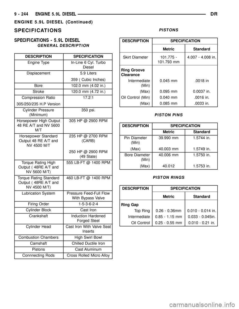
SPECIFICATIONS
SPECIFICATIONS - 5.9L DIESEL
GENERAL DESCRIPTION
DESCRIPTION SPECIFICATION
Engine Type In-Line 6 Cyl. Turbo
Diesel
Displacement 5.9 Liters
359 ( Cubic Inches)
Bore 102.0 mm (4.02 in.)
Stroke 120.0 mm (4.72 in.)
Compression Ratio 17.2:1
305/250/235 H.P Version
Cylinder Pressure
(Minimum)350 psi.
Horsepower High Output
48 RE A/T and NV 5600
M/T305 HP @ 2900 RPM
Horsepower Standard
Output 48 RE A/T and
NV 4500 M/T235 HP @ 2700 RPM
(CARB)
250 HP @ 2900 RPM
(49 State)
Torque Rating High
Output ( 48RE A/T and
NV 5600 M/T)555 LB-FT @ 1400 RPM
Torque Rating Standard
Output ( 48RE A/T and
NV 4500 M/T)460 LB-FT @ 1400 RPM
Lubrication System Pressure Feed-Full Flow
With Bypass Valve
Firing Order 1-5-3-6-2-4
Cylinder Block Cast Iron
Crankshaft Induction Hardened
Forged Steel
Cylinder Head Cast Iron With Valve Seat
Inserts
Combustion Chambers High Swirl Bowl
Camshaft Chilled Ductile Iron
Pistons Cast Aluminum
Connnecting Rods Cross Rolled Micro Alloy
PISTONS
DESCRIPTION SPECIFICATION
Metric Standard
Skirt Diameter 101.775 -
101.793 mm4.007 - 4.008 in.
Ring Groove
Clearance
Intermediate
(Min)0.045 mm .0018 in
(Max) 0.095 mm 0.0037 in.
Oil Control (Min) 0.040 mm .0016 in.
(Max) 0.085 mm .0033 in.
PISTON PINS
DESCRIPTION SPECIFICATION
Metric Standard
Pin Diameter
(Min)39.990 mm 1.5744 in.
(Max) 40.003 mm 1.5749 in.
Bore Diameter
(Min)40.006 mm 1.5750 in.
(Max) 40.012 1.5753 in.
PISTON RINGS
DESCRIPTION SPECIFICATION
Metric Standard
Ring Gap
Top Ring 0.26 - 0.36mm 0.010 - 0.014 in.
Intermediate 0.85 - 1.15 mm 0.033 - 0.045in.
Oil Control 0.25 - 0.55 mm 0.010 - 0.21 in.
9 - 244 ENGINE 5.9L DIESELDR
ENGINE 5.9L DIESEL (Continued)
Page 2213 of 2627
SELECTOR SWITCH
DESCRIPTION
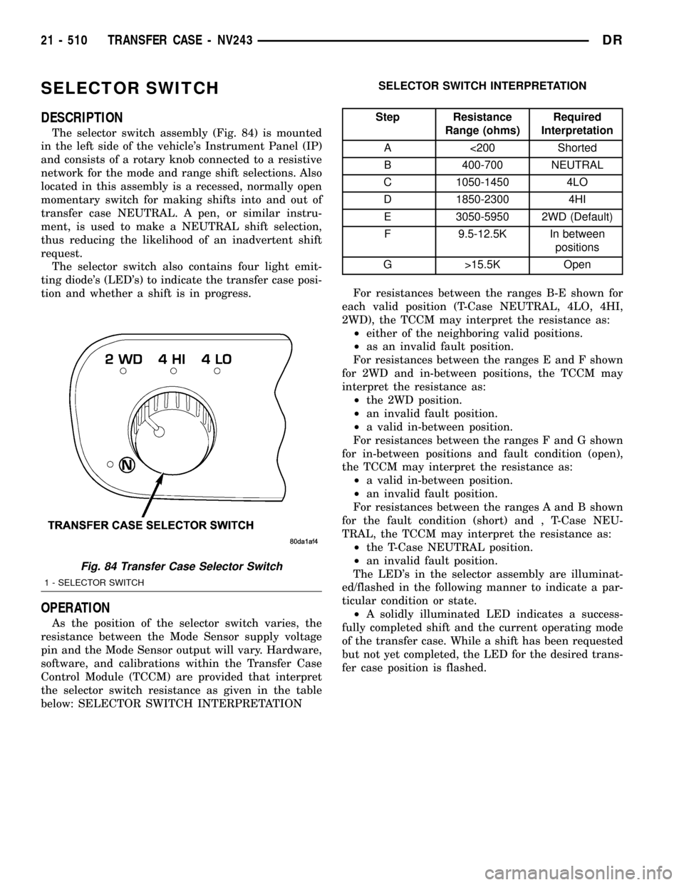
The selector switch assembly (Fig. 84) is mounted
in the left side of the vehicle's Instrument Panel (IP)
and consists of a rotary knob connected to a resistive
network for the mode and range shift selections. Also
located in this assembly is a recessed, normally open
momentary switch for making shifts into and out of
transfer case NEUTRAL. A pen, or similar instru-
ment, is used to make a NEUTRAL shift selection,
thus reducing the likelihood of an inadvertent shift
request.
The selector switch also contains four light emit-
ting diode's (LED's) to indicate the transfer case posi-
tion and whether a shift is in progress.
OPERATION
As the position of the selector switch varies, the
resistance between the Mode Sensor supply voltage
pin and the Mode Sensor output will vary. Hardware,
software, and calibrations within the Transfer Case
Control Module (TCCM) are provided that interpret
the selector switch resistance as given in the table
below: SELECTOR SWITCH INTERPRETATIONSELECTOR SWITCH INTERPRETATION
Step Resistance
Range (ohms)Required
Interpretation
A <200 Shorted
B 400-700 NEUTRAL
C 1050-1450 4LO
D 1850-2300 4HI
E 3050-5950 2WD (Default)
F 9.5-12.5K In between
positions
G >15.5K Open
For resistances between the ranges B-E shown for
each valid position (T-Case NEUTRAL, 4LO, 4HI,
2WD), the TCCM may interpret the resistance as:
²either of the neighboring valid positions.
²as an invalid fault position.
For resistances between the ranges E and F shown
for 2WD and in-between positions, the TCCM may
interpret the resistance as:
²the 2WD position.
²an invalid fault position.
²a valid in-between position.
For resistances between the ranges F and G shown
for in-between positions and fault condition (open),
the TCCM may interpret the resistance as:
²a valid in-between position.
²an invalid fault position.
For resistances between the ranges A and B shown
for the fault condition (short) and , T-Case NEU-
TRAL, the TCCM may interpret the resistance as:
²the T-Case NEUTRAL position.
²an invalid fault position.
The LED's in the selector assembly are illuminat-
ed/flashed in the following manner to indicate a par-
ticular condition or state.
²A solidly illuminated LED indicates a success-
fully completed shift and the current operating mode
of the transfer case. While a shift has been requested
but not yet completed, the LED for the desired trans-
fer case position is flashed.
Fig. 84 Transfer Case Selector Switch
1 - SELECTOR SWITCH
21 - 510 TRANSFER CASE - NV243DR
Page 2243 of 2627
OPERATION
As the position of the selector switch varies, the
resistance between the Mode Sensor supply voltage
pin and the Mode Sensor output will vary. Hardware,
software, and calibrations within the Transfer Case
Control Module (TCCM) are provided that interpret
the selector switch resistance as given in the table
below: SELECTOR SWITCH INTERPRETATION
SELECTOR SWITCH INTERPRETATION
Step Resistance
Range (ohms)Required
Interpretation
A <200 Shorted
B 400-700 NEUTRAL
C 1050-1450 4LO
D 1850-2300 4H
E 3050-5950 AWD (Default)
F 9.5-12.5K In between
positions
G >15.5K Open
For resistances between the ranges B-E shown for
each valid position (T-Case NEUTRAL, 4LO, 4HI,
AWD), the TCCM may interpret the resistance as:
²either of the neighboring valid positions.
²as an invalid fault position.
For resistances between the ranges E and F shown
for AWD and in-between positions, the TCCM may
interpret the resistance as:
²the AWD position.
²an invalid fault position.
²a valid in-between position.
For resistances between the ranges F and G shown
for in-between positions and fault condition (open),
the TCCM may interpret the resistance as:
²a valid in-between position.
²an invalid fault position.
For resistances between the ranges A and B shown
for the fault condition (short) and , T-Case NEU-
TRAL, the TCCM may interpret the resistance as:²the T-Case NEUTRAL position.
²an invalid fault position.
The LED's in the selector assembly are illuminat-
ed/flashed in the following manner to indicate a par-
ticular condition or state.
²A solidly illuminated LED indicates a success-
fully completed shift and the current operating mode
of the transfer case. While a shift has been requested
but not yet completed, the LED for the desired trans-
fer case position is flashed.
²A flashing operating mode LED for the desired
gear indicates that a shift to that position has been
requested, but all of the driver controllable conditions
have not been met. This is in an attempt to notify
the driver that the transmission needs to be put into
NEUTRAL, the vehicle speed is too great, or some
other condition outlined (other than a diagnostic fail-
ure that would prevent this shift) elsewhere (Refer to
8 - ELECTRICAL/ELECTRONIC CONTROL MOD-
ULES/TRANSFER CASE CONTROL MODULE -
OPERATION) is not met. Note that this flashing will
continue indefinitely until the conditions are eventu-
ally met, or the selector switch position is changed,
or if diagnostic routines no longer allow the
requested shift.
²If the driver attempts to make a shift into trans-
fer case NEUTRAL, and any of the driver controlla-
ble conditions are not met, the request will be
ignored until all of the conditions are met or until
the NEUTRAL select button is released. Additionally
the neutral lamp will flash, or begin to flash while
the button is depressed and operator controllable
conditions are not being met. All of the LED's except
the Neutral will flash if any of the operator control-
lable conditions for shifting are not met while the
Neutral button is depressed. This9toggle9type of fea-
ture is necessary because the TCCM would interpret
another request immediately after the shift into
transfer case NEUTRAL has completed.
²No LED's illuminated indicate a fault in the
transfer case control system.
21 - 540 TRANSFER CASE - NV244 GENIIDR
SELECTOR SWITCH (Continued)
Page 2277 of 2627
SELECTOR SWITCH
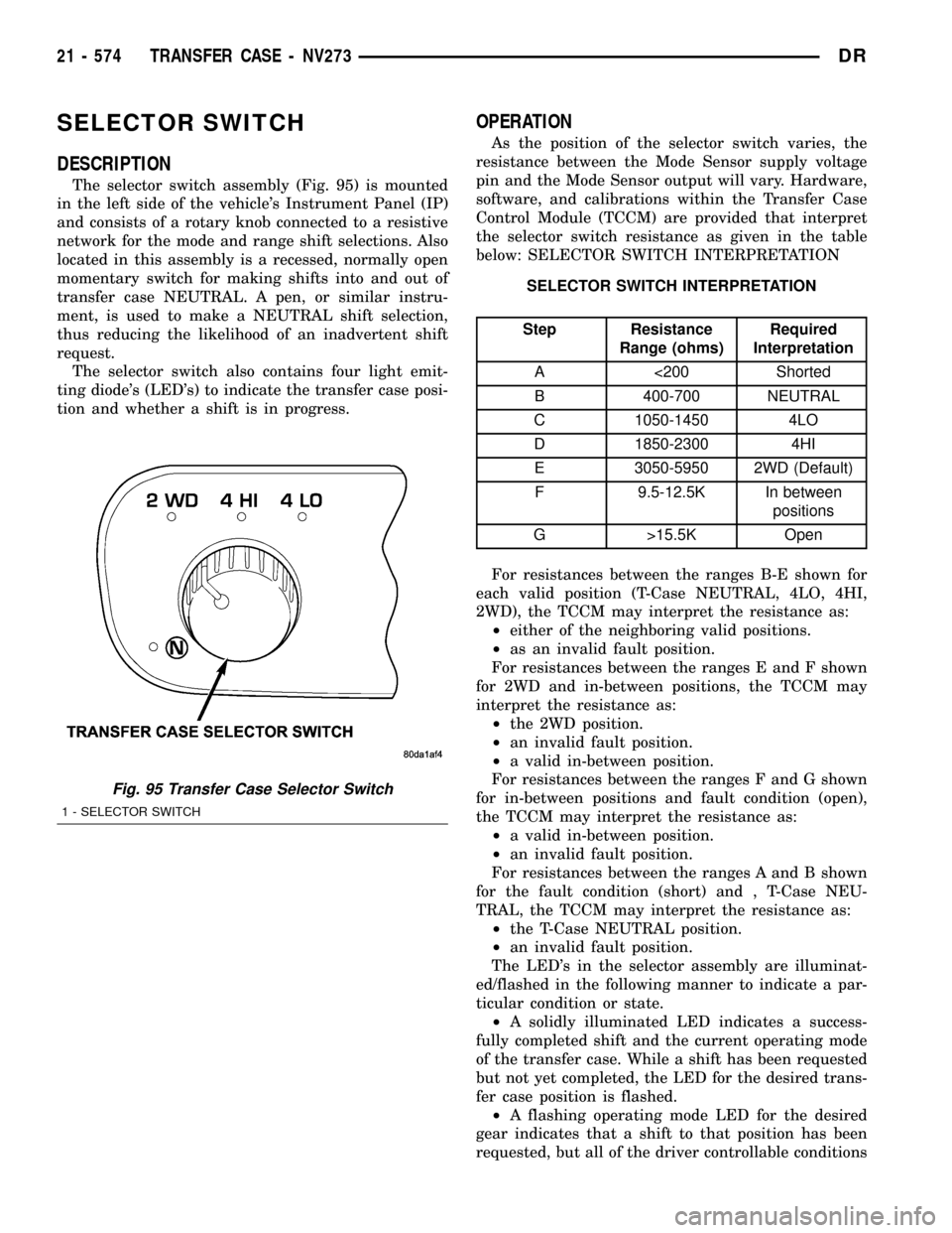
DESCRIPTION
The selector switch assembly (Fig. 95) is mounted
in the left side of the vehicle's Instrument Panel (IP)
and consists of a rotary knob connected to a resistive
network for the mode and range shift selections. Also
located in this assembly is a recessed, normally open
momentary switch for making shifts into and out of
transfer case NEUTRAL. A pen, or similar instru-
ment, is used to make a NEUTRAL shift selection,
thus reducing the likelihood of an inadvertent shift
request.
The selector switch also contains four light emit-
ting diode's (LED's) to indicate the transfer case posi-
tion and whether a shift is in progress.
OPERATION
As the position of the selector switch varies, the
resistance between the Mode Sensor supply voltage
pin and the Mode Sensor output will vary. Hardware,
software, and calibrations within the Transfer Case
Control Module (TCCM) are provided that interpret
the selector switch resistance as given in the table
below: SELECTOR SWITCH INTERPRETATION
SELECTOR SWITCH INTERPRETATION
Step Resistance
Range (ohms)Required
Interpretation
A <200 Shorted
B 400-700 NEUTRAL
C 1050-1450 4LO
D 1850-2300 4HI
E 3050-5950 2WD (Default)
F 9.5-12.5K In between
positions
G >15.5K Open
For resistances between the ranges B-E shown for
each valid position (T-Case NEUTRAL, 4LO, 4HI,
2WD), the TCCM may interpret the resistance as:
²either of the neighboring valid positions.
²as an invalid fault position.
For resistances between the ranges E and F shown
for 2WD and in-between positions, the TCCM may
interpret the resistance as:
²the 2WD position.
²an invalid fault position.
²a valid in-between position.
For resistances between the ranges F and G shown
for in-between positions and fault condition (open),
the TCCM may interpret the resistance as:
²a valid in-between position.
²an invalid fault position.
For resistances between the ranges A and B shown
for the fault condition (short) and , T-Case NEU-
TRAL, the TCCM may interpret the resistance as:
²the T-Case NEUTRAL position.
²an invalid fault position.
The LED's in the selector assembly are illuminat-
ed/flashed in the following manner to indicate a par-
ticular condition or state.
²A solidly illuminated LED indicates a success-
fully completed shift and the current operating mode
of the transfer case. While a shift has been requested
but not yet completed, the LED for the desired trans-
fer case position is flashed.
²A flashing operating mode LED for the desired
gear indicates that a shift to that position has been
requested, but all of the driver controllable conditions
Fig. 95 Transfer Case Selector Switch
1 - SELECTOR SWITCH
21 - 574 TRANSFER CASE - NV273DR