Tow plug DODGE RAM 1500 1998 2.G User Guide
[x] Cancel search | Manufacturer: DODGE, Model Year: 1998, Model line: RAM 1500, Model: DODGE RAM 1500 1998 2.GPages: 2627
Page 1261 of 2627

VALVE GUIDE SEALS
DESCRIPTION
The valve guide seals are made of rubber and
incorporate an integral steel valve spring seat. The
integral garter spring maintains consistent lubrica-
tion control to the valve stems.
VALVE SPRINGS
DESCRIPTION
The valve springs are made from high strength
chrome silicon steel. There are different springs for
intake and exhaust applications. The exhaust spring
has an external damper. The valve spring seat is
integral with the valve stem seal, which is a positive
type seal to control lubrication.
REMOVAL
(1) Remove the cylinder head cover(Refer to 9 -
ENGINE/CYLINDER HEAD/CYLINDER HEAD
COVER(S) - REMOVAL).
(2) Using Special Tool 8516 Valve Spring Compres-
sor, remove the rocker arms and the hydraulic lash
adjusters.
(3) Remove the spark plug for the cylinder the
valve spring and seal are to be removed from.
(4) Apply shop air to the cylinder to hold the
valves in place when the spring is removed.
NOTE: All six valve springs and seals are removed
in the same manner; this procedure only covers
one valve seal and valve spring.
(5) Using Special Tool 8387 Valve Spring Compres-
sor, compress the valve spring.
NOTE: It may be necessary to tap the top of the
valve spring to loosen the spring retainers locks
enough to be removed.
(6) Remove the two spring retainer lock halves.
NOTE: the valve spring is under tension use care
when releasing the valve spring compressor.
(7) Remove the valve spring compressor.
NOTE: The valve springs are NOT common between
intake and exhaust.
(8) Remove the spring retainer, and the spring.
(9) Remove the valve stem seal.
NOTE: The valve stem seals are common between
intake and exhaust.
INSTALLATION
NOTE: All six valve springs and seals are removed
in the same manner; this procedure only covers
one valve seal and valve spring.
(1) Apply shop air to the cylinder to hold the
valves in place while the spring is installed.
NOTE: The valve stem seals are common between
intake and exhaust.
(2) Install the valve stem seal.
NOTE: The valve springs are NOT common between
intake and exhaust.
(3) Install the spring retainer, and the spring.
(4) Using Special Tool 8387 Valve Spring Compres-
sor, compress the valve spring.
(5) Install the two spring retainer lock halves.
NOTE: the valve spring is under tension use care
when releasing the valve spring compressor.
(6) Remove the valve spring compressor.
(7) Disconnect the shop air to the cylinder.
(8) Install the spark plug for the cylinder the valve
spring and seal was installed on.
(9) Using Special Tool 8516 Valve Spring Compres-
sor, install the rocker arms and the hydraulic lash
adjusters.
(10) Install the cylinder head cover(Refer to 9 -
ENGINE/CYLINDER HEAD/CYLINDER HEAD
COVER(S) - INSTALLATION).
ENGINE BLOCK
DESCRIPTION
The cylinder block is made of cast iron. The block
is a closed deck design with the left bank forward. To
provide high rigidity and improved NVH an
enhanced compacted graphite bedplate is bolted to
the block. The block design allows coolant flow
between the cylinders bores, and an internal coolant
bypass to a single poppet inlet thermostat is included
in the cast aluminum front cover.
STANDARD PROCEDURE - CYLINDER BORE
HONING
Before honing, stuff plenty of clean shop towels
under the bores and over the crankshaft to keep
abrasive materials from entering the crankshaft
area.
(1) Used carefully, the Cylinder Bore Sizing Hone
C-823, equipped with 220 grit stones, is the best tool
9 - 38 ENGINE - 3.7LDR
Page 1351 of 2627

ENGINE BLOCK
DESCRIPTION
The cylinder block is made of cast iron. The block
is a closed deck design with the left bank forward. To
provide high rigidity and improved NVH an
enhanced compacted graphite bedplate is bolted to
the block. The block design allows coolant flow
between the cylinders bores, and an internal coolant
bypass to a single poppet inlet thermostat is included
in the cast aluminum front cover.
STANDARD PROCEDURE - CYLINDER BORE
HONING
Before honing, stuff plenty of clean shop towels
under the bores and over the crankshaft to keep
abrasive materials from entering the crankshaft
area.
(1) Used carefully, the Cylinder Bore Sizing Hone
C-823, equipped with 220 grit stones, is the best tool
for this job. In addition to deglazing, it will reduce
taper and out-of-round, as well as removing light
scuffing, scoring and scratches. Usually, a few strokes
will clean up a bore and maintain the required lim-
its.
CAUTION: DO NOT use rigid type hones to remove
cylinder wall glaze.
(2) Deglazing of the cylinder walls may be done if
the cylinder bore is straight and round. Use a cylin-
der surfacing hone, Honing Tool C-3501, equipped
with 280 grit stones (C-3501-3810). about 20-60
strokes, depending on the bore condition, will be suf-
ficient to provide a satisfactory surface. Using honing
oil C-3501-3880, or a light honing oil, available from
major oil distributors.
CAUTION: DO NOT use engine or transmission oil,
mineral spirits, or kerosene.
(3) Honing should be done by moving the hone up
and down fast enough to get a crosshatch pattern.
The hone marks should INTERSECT at 50É to 60É
for proper seating of rings (Fig. 48).
(4) A controlled hone motor speed between 200 and
300 RPM is necessary to obtain the proper cross-
hatch angle. The number of up and down strokes per
minute can be regulated to get the desired 50É to 60É
angle. Faster up and down strokes increase the cross-
hatch angle.
(5) After honing, it is necessary that the block be
cleaned to remove all traces of abrasive. Use a brush
to wash parts with a solution of hot water and deter-
gent. Dry parts thoroughly. Use a clean, white, lint-free cloth to check that the bore is clean. Oil the
bores after cleaning to prevent rusting.
CLEANING
Thoroughly clean the oil pan and engine block gas-
ket surfaces.
Use compressed air to clean out:
²The galley at the oil filter adaptor hole.
²The front and rear oil galley holes.
²The feed holes for the crankshaft main bearings.
Once the block has been completely cleaned, apply
Loctite PST pipe sealant with Teflon 592 to the
threads of the front and rear oil galley plugs. Tighten
the 1/4 inch NPT plugs to 20 N´m (177 in. lbs.)
torque. Tighten the 3/8 inch NPT plugs to 27 N´m
(240 in. lbs.) torque.
INSPECTION
(1) It is mandatory to use a dial bore gauge to
measure each cylinder bore diameter. To correctly
select the proper size piston, a cylinder bore gauge,
capable of reading in 0.003 mm (.0001 in.) INCRE-
MENTS is required. If a bore gauge is not available,
do not use an inside micrometer (Fig. 49).
(2) Measure the inside diameter of the cylinder
bore at three levels below top of bore. Start perpen-
dicular (across or at 90 degrees) to the axis of the
crankshaft and then take two additional reading.
(3) Measure the cylinder bore diameter crosswise
to the cylinder block near the top of the bore. Repeat
Fig. 48 CYLINDER BORE CROSSHATCH PATTERN
1 - CROSSHATCH PATTERN
2 - INTERSECT ANGLE
9 - 128 ENGINE - 4.7LDR
Page 1413 of 2627
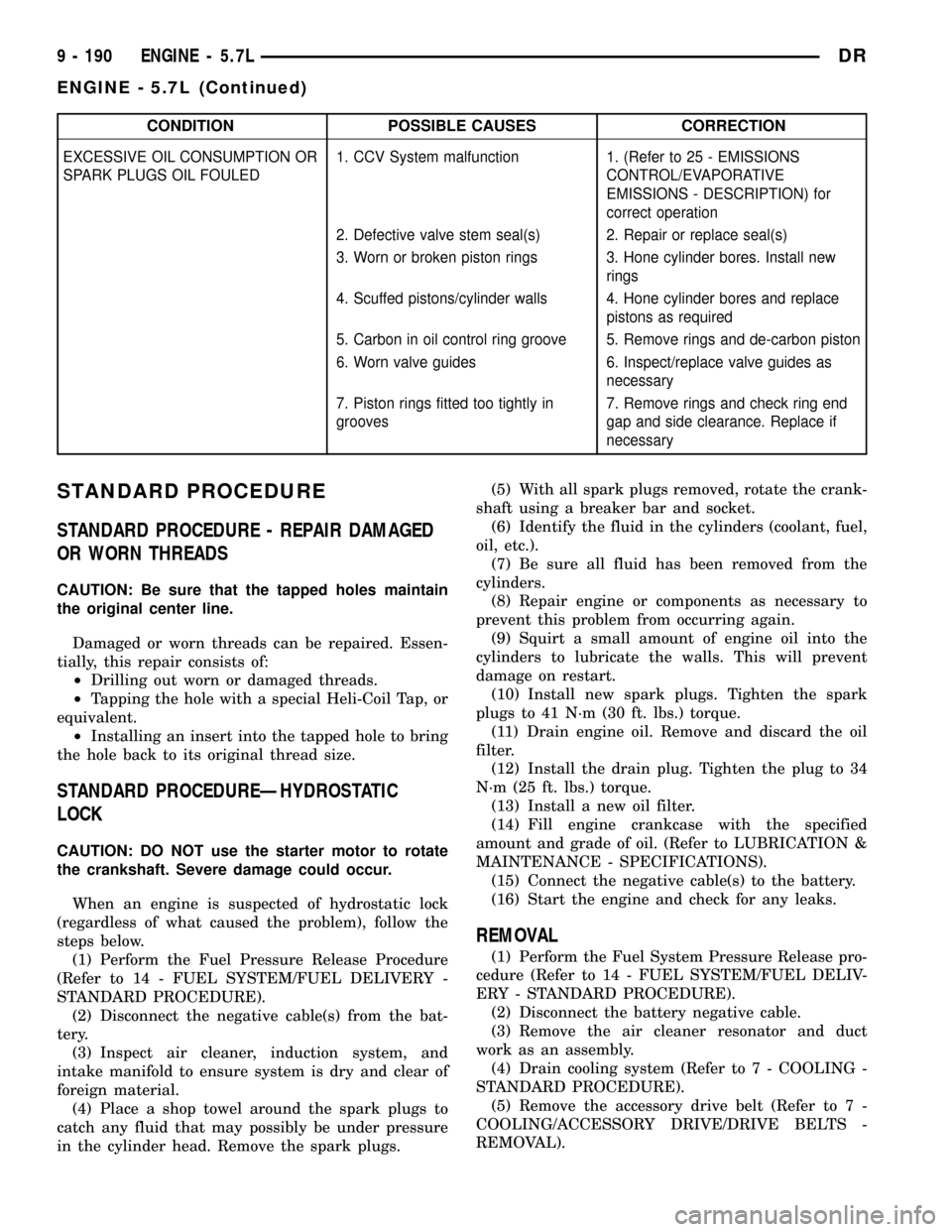
CONDITION POSSIBLE CAUSES CORRECTION
EXCESSIVE OIL CONSUMPTION OR
SPARK PLUGS OIL FOULED1. CCV System malfunction 1. (Refer to 25 - EMISSIONS
CONTROL/EVAPORATIVE
EMISSIONS - DESCRIPTION) for
correct operation
2. Defective valve stem seal(s) 2. Repair or replace seal(s)
3. Worn or broken piston rings 3. Hone cylinder bores. Install new
rings
4. Scuffed pistons/cylinder walls 4. Hone cylinder bores and replace
pistons as required
5. Carbon in oil control ring groove 5. Remove rings and de-carbon piston
6. Worn valve guides 6. Inspect/replace valve guides as
necessary
7. Piston rings fitted too tightly in
grooves7. Remove rings and check ring end
gap and side clearance. Replace if
necessary
STANDARD PROCEDURE
STANDARD PROCEDURE - REPAIR DAMAGED
OR WORN THREADS
CAUTION: Be sure that the tapped holes maintain
the original center line.
Damaged or worn threads can be repaired. Essen-
tially, this repair consists of:
²Drilling out worn or damaged threads.
²Tapping the hole with a special Heli-Coil Tap, or
equivalent.
²Installing an insert into the tapped hole to bring
the hole back to its original thread size.
STANDARD PROCEDUREÐHYDROSTATIC
LOCK
CAUTION: DO NOT use the starter motor to rotate
the crankshaft. Severe damage could occur.
When an engine is suspected of hydrostatic lock
(regardless of what caused the problem), follow the
steps below.
(1) Perform the Fuel Pressure Release Procedure
(Refer to 14 - FUEL SYSTEM/FUEL DELIVERY -
STANDARD PROCEDURE).
(2) Disconnect the negative cable(s) from the bat-
tery.
(3) Inspect air cleaner, induction system, and
intake manifold to ensure system is dry and clear of
foreign material.
(4) Place a shop towel around the spark plugs to
catch any fluid that may possibly be under pressure
in the cylinder head. Remove the spark plugs.(5) With all spark plugs removed, rotate the crank-
shaft using a breaker bar and socket.
(6) Identify the fluid in the cylinders (coolant, fuel,
oil, etc.).
(7) Be sure all fluid has been removed from the
cylinders.
(8) Repair engine or components as necessary to
prevent this problem from occurring again.
(9) Squirt a small amount of engine oil into the
cylinders to lubricate the walls. This will prevent
damage on restart.
(10) Install new spark plugs. Tighten the spark
plugs to 41 N´m (30 ft. lbs.) torque.
(11) Drain engine oil. Remove and discard the oil
filter.
(12) Install the drain plug. Tighten the plug to 34
N´m (25 ft. lbs.) torque.
(13) Install a new oil filter.
(14) Fill engine crankcase with the specified
amount and grade of oil. (Refer to LUBRICATION &
MAINTENANCE - SPECIFICATIONS).
(15) Connect the negative cable(s) to the battery.
(16) Start the engine and check for any leaks.
REMOVAL
(1) Perform the Fuel System Pressure Release pro-
cedure (Refer to 14 - FUEL SYSTEM/FUEL DELIV-
ERY - STANDARD PROCEDURE).
(2) Disconnect the battery negative cable.
(3) Remove the air cleaner resonator and duct
work as an assembly.
(4) Drain cooling system (Refer to 7 - COOLING -
STANDARD PROCEDURE).
(5) Remove the accessory drive belt (Refer to 7 -
COOLING/ACCESSORY DRIVE/DRIVE BELTS -
REMOVAL).
9 - 190 ENGINE - 5.7LDR
ENGINE - 5.7L (Continued)
Page 1462 of 2627

DIAGNOSIS AND TESTING - CYLINDER
COMPRESSION/LEAKAGE TESTS
CYLINDER COMPRESSION PRESSURE
The results of a cylinder compression pressure test
can be utilized to diagnose several engine malfunc-
tions.
Ensure batteries are completely charged and the
engine starter motor is in good operating condition.
Otherwise, the indicated compression pressures may
not be valid for diagnostic purposes.
(1) Disconnect the fuel inlet line to the fuel trans-
fer pump. Plug the fuel line from the fuel tank.
(2) Start the engine and idle until the engine stalls
(runs out of fuel).
(3) Disconnect all three injector wire harness con-
nectors at the rocker housing.
(4) Remove the breather cover and cylinder head
cover.
(5) Remove the high pressure fuel line between the
cylinder head and fuel rail for the cylinder to be
tested. Use tool# 9011 to cap this fuel rail on the cyl-
inder being tested.
(6) Remove the exhaust rocker lever.
(7) Use Tool 9010 to remove the injector and cop-
per sealing washer.
(8) Install the exhaust rocker lever and torque to
36 N´m (27 ft. lbs.).
(9) Cover the remaining rocker levers with clean
shop towels to prevent any oil splatter under the
hood.
(10) Place a rag over the compression test tool fit-
ting. Crank the engine for 2±3 seconds to purge any
fuel that may have drained into the cylinder when
the injector was removed.
(11) Connect the compression test gauge.
(12) Crank the engine for 5 seconds and record the
pressure reading. Repeat this step three times and
calculate the average of the three readings.
NOTE: The minimum cylinder pressure is 350 psi.
Cylinder pressure should be within 20% from cylin-
der to cylinder.
(13) Combustion pressure leakage can be checked
if cylinder pressure is below the specification. Per-
form the leakage test procedure on each cylinder
according to the tester manufacturer instructions.
(14) Upon completion of the test check an erase
any engine related fault codes.
CYLINDER COMBUSTION PRESSURE LEAKAGE
The combustion pressure leakage test provides an
accurate means for determining engine condition.
Combustion pressure leakage testing will detect:²Exhaust and intake valve leaks (improper seat-
ing).
²Leaks between adjacent cylinders or into water
jacket.
²Any causes for combustion/compression pressure
loss
(1) Start and operate the engine until it attains
normal operating temperature.
(2) Remove the breather cover and cylinder head
cover.
(3) Disconnect all three injector wire harness con-
nectors at the rocker housing.
(4) Bring the cylinder to be tested to TDC.
(5) Remove the high pressure fuel line between the
cylinder head and the fuel rail for the cylinder to be
tested.
(6) Install capping Tool 9011 onto the rail.
(7) Remove the high pressure connector nut and
high pressure connector with Tool 9015.
(8) Remove the exhaust and intake rocker lever.
(9) Use Tool 9010 to remove the injector and cop-
per sealing washer.
(10) Install compression test Tool 9007 into the
injector bore.
(11) Connect the leakage tester and perform the
leakage test procedure on each cylinder according to
the tester manufacturer's instructions.
(12) Upon completion of the test check and erase
any engine related fault codes.
STANDARD PROCEDURE
STANDARD PROCEDURE - FORM-IN-PLACE
GASKETS AND SEALERS
There are numerous places where form-in-place
gaskets are used on the engine. Care must be taken
when applying form-in-place gaskets to assure
obtaining the desired results.Do not use form-in-
place gasket material unless specified.Bead size,
continuity, and location are of great importance. Too
thin a bead can result in leakage while too much can
result in spill-over which can break off and obstruct
fluid feed lines. A continuous bead of the proper
width is essential to obtain a leak-free gasket.
There are numerous types of form-in-place gasket
materials that are used in the engine area. Mopart
Engine RTV GEN II, MopartATF-RTV, and Mopart
Gasket Maker gasket materials, each have different
properties and can not be used in place of the other.
MOPARtENGINE RTV GEN II
MopartEngine RTV GEN II is used to seal com-
ponents exposed to engine oil. This material is a spe-
cially designed black silicone rubber RTV that
retains adhesion and sealing properties when
exposed to engine oil. Moisture in the air causes the
DRENGINE 5.9L DIESEL 9 - 239
ENGINE 5.9L DIESEL (Continued)
Page 1572 of 2627
(2) Remove fuel pump relay from Power Distribu-
tion Center (PDC). For location of relay, refer to label
on underside of PDC cover.
(3) Start and run engine until it stalls.
(4) Attempt restarting engine until it will no
longer run.
(5) Turn ignition key to OFF position.
CAUTION: Steps 1, 2, 3 and 4 must be performed to
relieve high pressure fuel from within fuel rail. Do
not attempt to use following steps to relieve this
pressure as excessive fuel will be forced into a cyl-
inder chamber.
(6) Unplug connector from any fuel injector.
(7) Attach one end of a jumper wire with alligator
clips (18 gauge or smaller) to either injector terminal.
(8) Connect other end of jumper wire to positive
side of battery.(9) Connect one end of a second jumper wire to
remaining injector terminal.
CAUTION: Powering an injector for more than a few
seconds will permanently damage the injector.
(10) Momentarily touch other end of jumper wire
to negative terminal of battery for no more than a
few seconds.
(11) Place a rag or towel below fuel line quick-con-
nect fitting at fuel rail.
(12) Disconnect quick-connect fitting at fuel rail.
Refer to Quick-Connect Fittings.
(13) Return fuel pump relay to PDC.
(14) One or more Diagnostic Trouble Codes (DTC's)
may have been stored in PCM memory due to fuel
pump relay removal. The DRBtscan tool must be
used to erase a DTC.
SPECIFICATIONS
FUEL SYSTEM PRESSURE
58 psi +/- 2 psi
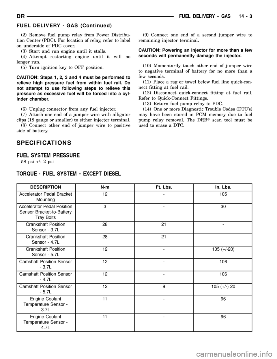
TORQUE - FUEL SYSTEM - EXCEPT DIESEL
DESCRIPTION N-m Ft. Lbs. In. Lbs.
Accelerator Pedal Bracket
Mounting12 - 105
Accelerator Pedal Position
Sensor Bracket-to-Battery
Tray Bolts3-30
Crankshaft Position
Sensor - 3.7L28 21 -
Crankshaft Position
Sensor - 4.7L28 21 -
Crankshaft Position
Sensor - 5.7L12 - 105 (+/-20)
Camshaft Position Sensor
- 3.7L12 - 106
Camshaft Position Sensor
- 4.7L12 - 106
Camshaft Position Sensor
- 5.7L12 9 105 (+/-) 20
Engine Coolant
Temperature Sensor -
3.7L11 - 9 6
Engine Coolant
Temperature Sensor -
4.7L11 - 9 6
DRFUEL DELIVERY - GAS 14 - 3
FUEL DELIVERY - GAS (Continued)
Page 1627 of 2627

WARNING: USE EXTREME CAUTION WHEN
INSPECTING FOR HIGH-PRESSURE FUEL LEAKS.
INSPECT FOR HIGH-PRESSURE FUEL LEAKS WITH
A SHEET OF CARDBOARD. HIGH FUEL INJECTION
PRESSURE CAN CAUSE PERSONAL INJURY IF
CONTACT IS MADE WITH THE SKIN.
DIAGNOSIS AND TESTING - HIGH-PRESSURE
FUEL LINE LEAKS
High-pressure fuel line leaks can cause starting
problems and poor engine performance.
WARNING: DUE TO EXTREME FUEL PRESSURES
OF UP TO 160,000 kPa (23,206 PSI), USE EXTREME
CAUTION WHEN INSPECTING FOR HIGH-PRES-
SURE FUEL LEAKS. DO NOT GET YOUR HAND OR
A FINGER NEAR A SUSPECTED LEAK. INSPECT
FOR HIGH-PRESSURE FUEL LEAKS WITH A SHEET
OF CARDBOARD. HIGH FUEL INJECTION PRES-
SURE CAN CAUSE PERSONAL INJURY IF CON-
TACT IS MADE WITH THE SKIN.
Start the engine. Move the cardboard (Fig. 13) over
the suspected high-pressure fuel line leak, and check
for fuel spray onto the cardboard. If line is leaking,
retorque line. Replace damaged, restricted or leaking
high-pressure fuel lines with the correct replacement
line.
CAUTION: The high-pressure fuel lines must be
clamped securely in place in the holders. The lines
cannot contact each other or other components. Do
not attempt to weld high-pressure fuel lines or to
repair lines that are damaged. Only use the recom-
mended lines when replacement of high-pressure
fuel line is necessary.
REMOVAL
CAUTION: Cleanliness cannot be overemphasized
when handling or replacing diesel fuel system com-
ponents. This especially includes the fuel injectors,
high-pressure fuel lines and fuel injection pump.
Very tight tolerances are used with these parts. Dirt
contamination could cause rapid part wear and pos-
sible plugging of fuel injector nozzle tip holes. This
in turn could lead to possible engine misfire.
Always wash/clean any fuel system component
thoroughly before disassembly and then air dry.
Cap or cover any open part after disassembly.
Before assembly, examine each part for dirt, grease
or other contaminants and clean if necessary. When
installing new parts, lubricate them with clean
engine oil or clean diesel fuel only.
(1) Disconnect both negative battery cables from
both batteries. Cover and isolate ends of cables.(2) Thoroughly clean fuel lines at both ends.
(3) If removing fuel line at either #1 or #2 cylinder,
the intake manifold air heater elements must first be
removed from top of intake manifold. Refer to Intake
Air Heater Removal / Installation for procedures.
(4) If removing fuel line at #6 cylinder, a bracket
(Fig. 14) is located above fuel line connection at cyl-
inder head. Two bolts secure this bracket to rear of
cylinder head. The upper bolt hole is slotted. Loosen
(but do not remove) these 2 bracket bolts. Tilt
bracket down to gain access to #6 fuel line connec-
tion.
(5) Remove engine lift bracket (if necessary).
(6) Remove necessary insulated fuel line support
clamps (Fig. 15) and bracket bolts at intake manifold.
DO NOT remove insulators from fuel lines.
(7) Place shop towels around fuel lines at fuel rail
and injectors. If possible, do not allow fuel to drip
down side of engine.
CAUTION: WHEN LOOSENING OR TIGHTENING
HIGH-PRESSURE LINES ATTACHED TO A SEPA-
RATE FITTING (Fig. 16) , USE A BACK-UP WRENCH
ON FITTING. DO NOT ALLOW FITTING TO ROTATE.
DAMAGE TO BOTH FUEL LINE AND FITTING WILL
RESULT.
(8) Carefully remove each fuel line from engine.
Note position of each while removing.Do not bend
lines while removing.
Fig. 13 TYPICAL TEST FOR LEAKS USING
CARDBOARD
1 - HIGH-PRESSURE LINE
2 - CARDBOARD
3 - TYPICAL HIGH-PRESSURE FITTING
14 - 58 FUEL DELIVERY - DIESELDR
FUEL LINES (Continued)
Page 1707 of 2627
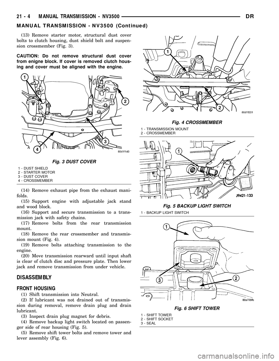
(13) Remove starter motor, structural dust cover
bolts to clutch housing, dust shield bolt and suspen-
sion crossmember (Fig. 3).
CAUTION: Do not remove structural dust cover
from enigne block. If cover is removed clutch hous-
ing and cover must be aligned with the engine.
(14) Remove exhaust pipe from the exhaust mani-
folds.
(15) Support engine with adjustable jack stand
and wood block.
(16) Support and secure transmission to a trans-
mission jack with safety chains.
(17) Remove bolts from the rear transmission
mount.
(18) Remove the rear crossmember and transmis-
sion mount (Fig. 4).
(19) Remove bolts attaching transmission to the
engine.
(20) Move transmission rearward until input shaft
is clear of clutch disc and pressure plate. Then lower
jack and remove transmission from under vehicle.
DISASSEMBLY
FRONT HOUSING
(1) Shift transmission into Neutral.
(2) If lubricant was not drained out of transmis-
sion during removal, remove drain plug and drain
lubricant.
(3) Inspect drain plug magnet for debris.
(4) Remove backup light switch located on passen-
ger side of rear housing (Fig. 5).
(5) Remove shift tower bolts and remove tower and
lever assembly (Fig. 6).
Fig. 3 DUST COVER
1 - DUST SHIELD
2 - STARTER MOTOR
3 - DUST COVER
4 - CROSSMEMBER
Fig. 4 CROSSMEMBER
1 - TRANSMISSION MOUNT
2 - CROSSMEMBER
Fig. 5 BACKUP LIGHT SWITCH
1 - BACKUP LIGHT SWITCH
Fig. 6 SHIFT TOWER
1 - SHIFT TOWER
2 - SHIFT SOCKET
3 - SEAL
21 - 4 MANUAL TRANSMISSION - NV3500DR
MANUAL TRANSMISSION - NV3500 (Continued)
Page 1741 of 2627
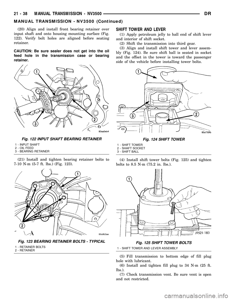
(20) Align and install front bearing retainer over
input shaft and onto housing mounting surface (Fig.
122). Verify bolt holes are aligned before seating
retainer.
CAUTION: Be sure sealer does not get into the oil
feed hole in the transmission case or bearing
retainer.
(21) Install and tighten bearing retainer bolts to
7-10 N´m (5-7 ft. lbs.) (Fig. 123).SHIFT TOWER AND LEVER
(1) Apply petroleum jelly to ball end of shift lever
and interior of shift socket.
(2) Shift the transmission into third gear.
(3) Align and install shift tower and lever assem-
bly (Fig. 124). Be sure shift ball is seated in socket
and the offset in the tower is toward the passenger
side of the vehicle before installing tower bolts.
(4) Install shift tower bolts (Fig. 125) and tighten
bolts to 8.5 N´m (75.2 in. lbs.).
(5) Fill transmission to bottom edge of fill plug
hole with lubricant.
(6) Install and tighten fill plug to 34 N´m (25 ft.
lbs.).
(7) Check transmission vent. Be sure vent is open
and not restricted.
Fig. 122 INPUT SHAFT BEARING RETAINER
1 - INPUT SHAFT
2 - OIL FEED
3 - BEARING RETAINER
Fig. 123 BEARING RETAINER BOLTS - TYPICAL
1 - RETAINER BOLTS
2 - RETAINER
Fig. 124 SHIFT TOWER
1 - SHIFT TOWER
2 - SHAFT SOCKET
3 - SHIFT BALL
Fig. 125 SHIFT TOWER BOLTS
1 - SHIFT TOWER AND LEVER ASSEMBLY
21 - 38 MANUAL TRANSMISSION - NV3500DR
MANUAL TRANSMISSION - NV3500 (Continued)
Page 1742 of 2627
INSTALLATION
NOTE: If a new transmission is being installed, use
all components supplied with the new transmission.
For example, if a new shift tower is supplied, do not
re-use the original shift tower.
(1) Clean transmission front housing mounting
surface.
(2) Apply light coat of Mopar high temperature
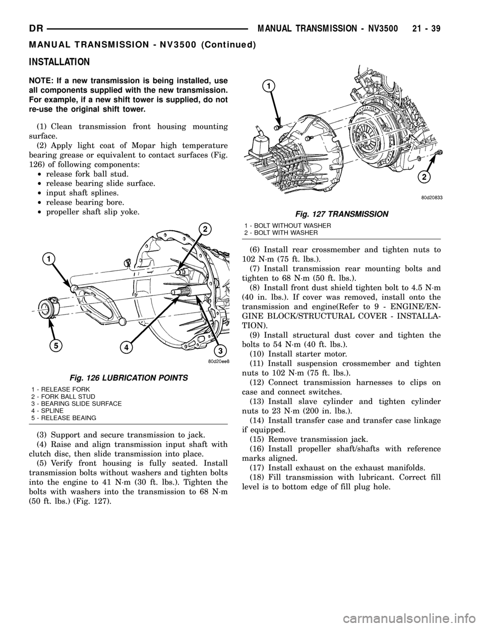
bearing grease or equivalent to contact surfaces (Fig.
126) of following components:
²release fork ball stud.
²release bearing slide surface.
²input shaft splines.
²release bearing bore.
²propeller shaft slip yoke.
(3) Support and secure transmission to jack.
(4) Raise and align transmission input shaft with
clutch disc, then slide transmission into place.
(5) Verify front housing is fully seated. Install
transmission bolts without washers and tighten bolts
into the engine to 41 N´m (30 ft. lbs.). Tighten the
bolts with washers into the transmission to 68 N´m
(50 ft. lbs.) (Fig. 127).(6) Install rear crossmember and tighten nuts to
102 N´m (75 ft. lbs.).
(7) Install transmission rear mounting bolts and
tighten to 68 N´m (50 ft. lbs.).
(8) Install front dust shield tighten bolt to 4.5 N´m
(40 in. lbs.). If cover was removed, install onto the
transmission and engine(Refer to 9 - ENGINE/EN-
GINE BLOCK/STRUCTURAL COVER - INSTALLA-
TION).
(9) Install structural dust cover and tighten the
bolts to 54 N´m (40 ft. lbs.).
(10) Install starter motor.
(11) Install suspension crossmember and tighten
nuts to 102 N´m (75 ft. lbs.).
(12) Connect transmission harnesses to clips on
case and connect switches.
(13) Install slave cylinder and tighten cylinder
nuts to 23 N´m (200 in. lbs.).
(14) Install transfer case and transfer case linkage
if equipped.
(15) Remove transmission jack.
(16) Install propeller shaft/shafts with reference
marks aligned.
(17) Install exhaust on the exhaust manifolds.
(18) Fill transmission with lubricant. Correct fill
level is to bottom edge of fill plug hole.
Fig. 126 LUBRICATION POINTS
1 - RELEASE FORK
2 - FORK BALL STUD
3 - BEARING SLIDE SURFACE
4 - SPLINE
5 - RELEASE BEAING
Fig. 127 TRANSMISSION
1 - BOLT WITHOUT WASHER
2 - BOLT WITH WASHER
DRMANUAL TRANSMISSION - NV3500 21 - 39
MANUAL TRANSMISSION - NV3500 (Continued)
Page 1743 of 2627
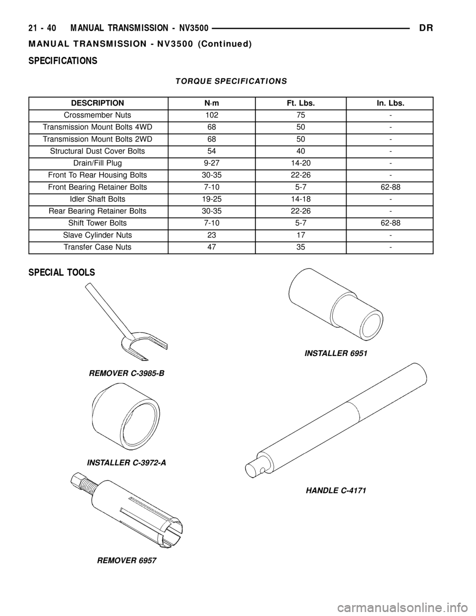
SPECIFICATIONS
TORQUE SPECIFICATIONS
DESCRIPTION N´m Ft. Lbs. In. Lbs.
Crossmember Nuts 102 75 -
Transmission Mount Bolts 4WD 68 50 -
Transmission Mount Bolts 2WD 68 50 -
Structural Dust Cover Bolts 54 40 -
Drain/Fill Plug 9-27 14-20 -
Front To Rear Housing Bolts 30-35 22-26 -
Front Bearing Retainer Bolts 7-10 5-7 62-88
Idler Shaft Bolts 19-25 14-18 -
Rear Bearing Retainer Bolts 30-35 22-26 -
Shift Tower Bolts 7-10 5-7 62-88
Slave Cylinder Nuts 23 17 -
Transfer Case Nuts 47 35 -
SPECIAL TOOLS
REMOVER C-3985-B
INSTALLER C-3972-A
REMOVER 6957
INSTALLER 6951
HANDLE C-4171
21 - 40 MANUAL TRANSMISSION - NV3500DR
MANUAL TRANSMISSION - NV3500 (Continued)