Tow plug DODGE RAM 1500 1998 2.G Workshop Manual
[x] Cancel search | Manufacturer: DODGE, Model Year: 1998, Model line: RAM 1500, Model: DODGE RAM 1500 1998 2.GPages: 2627
Page 14 of 2627
LUBRICATION & MAINTENANCE
TABLE OF CONTENTS
page page
FLUID TYPES
DESCRIPTION
DESCRIPTION - FUEL REQUIREMENTS -
DIESEL ENGINE.......................1
DESCRIPTION - ENGINE OIL AND
LUBRICANTS.........................1
DESCRIPTION - ENGINE OIL - DIESEL
ENGINES............................2
DESCRIPTION - POWER STEERING FLUID . . 3
DESCRIPTION - ENGINE COOLANT........3
DESCRIPTION - TRANSFER CASE.........4
DESCRIPTION - AXLE...................4
DESCRIPTION - MANUAL TRANSMISSION . . . 4
DESCRIPTION - AUTOMATIC
TRANSMISSION FLUID..................4
OPERATION - AUTOMATIC TRANSMISSION
FLUID...............................5FLUID CAPACITIES
SPECIFICATIONS
FLUID CAPACITIES.....................5
MAINTENANCE SCHEDULES
DESCRIPTION
DESCRIPTION........................6
MAINTENANCE SCHEDULES Ð 24±VALVE
CUMMINS TURBO DIESEL..............12
JUMP STARTING
STANDARD PROCEDURE - JUMP STARTING . 19
HOISTING
STANDARD PROCEDURE - HOISTING.......20
TOWING
STANDARD PROCEDURE - TOWING........21
FLUID TYPES
DESCRIPTION
DESCRIPTION - FUEL REQUIREMENTS -
DIESEL ENGINE
DESCRIPTION
WARNING: Do not use alcohol or gasoline as a fuel
blending agent. They can be unstable under certain
conditions and hazardous or explosive when mixed
with diesel fuel.
Use good quality diesel fuel from a reputable sup-
plier in your Dodge truck. For most year-round ser-
vice, number 2 diesel fuel meeting ASTM
specification D-975 will provide good performance. If
the vehicle is exposed to extreme cold (below 0ÉF/-
18ÉC), or is required to operate at colder-than-normal
conditions for prolonged periods, use climatized No. 2
diesel fuel or dilute the No. 2 diesel fuel with 50%
No. 1 diesel fuel. This will provide better protection
from fuel gelling or wax-plugging of the fuel filters.
Diesel fuel is seldom completely free of water. To
prevent fuel system trouble, including fuel line freez-
ing in winter, drain the accumulated water from the
fuel/water separator using the fuel/water separator
drain provided. If you buy good-quality fuel and fol-low the cold-weather advice above, fuel conditioners
should not be required in your vehicle. If available in
your area, a high cetane ªpremiumº diesel fuel may
offer improved cold starting and warm-up perfor-
mance.
DESCRIPTION - ENGINE OIL AND LUBRICANTS
WARNING: NEW OR USED ENGINE OIL CAN BE
IRRITATING TO THE SKIN. AVOID PROLONGED OR
REPEATED SKIN CONTACT WITH ENGINE OIL.
CONTAMINANTS IN USED ENGINE OIL, CAUSED BY
INTERNAL COMBUSTION, CAN BE HAZARDOUS TO
YOUR HEALTH. THOROUGHLY WASH EXPOSED
SKIN WITH SOAP AND WATER. DO NOT WASH
SKIN WITH GASOLINE, DIESEL FUEL, THINNER, OR
SOLVENTS, HEALTH PROBLEMS CAN RESULT. DO
NOT POLLUTE, DISPOSE OF USED ENGINE OIL
PROPERLY. CONTACT YOUR DEALER OR GOVERN-
MENT AGENCY FOR LOCATION OF COLLECTION
CENTER IN YOUR AREA.
When service is required, DaimlerChrysler Corpo-
ration recommends that only Mopartbrand parts,
lubricants and chemicals be used. Mopartprovides
the best engineered products for servicing
DaimlerChrysler Corporation vehicles.
Only lubricants bearing designations defined by
the following organization should be used.
²Society of Automotive Engineers (SAE)
²American Petroleum Institute (API)
DRLUBRICATION & MAINTENANCE 0 - 1
Page 20 of 2627
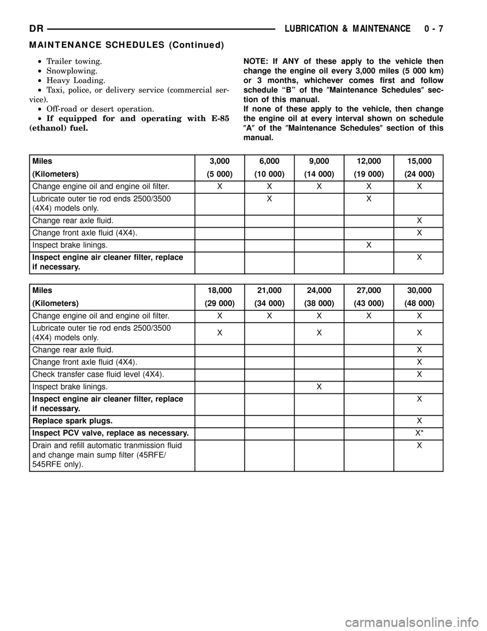
²Trailer towing.
²Snowplowing.
²Heavy Loading.
²Taxi, police, or delivery service (commercial ser-
vice).
²Off-road or desert operation.
²If equipped for and operating with E-85
(ethanol) fuel.NOTE: If ANY of these apply to the vehicle then
change the engine oil every 3,000 miles (5 000 km)
or 3 months, whichever comes first and follow
schedule ªBº of the(Maintenance Schedules(sec-
tion of this manual.
If none of these apply to the vehicle, then change
the engine oil at every interval shown on schedule
(A(of the(Maintenance Schedules(section of this
manual.
Miles 3,000 6,000 9,000 12,000 15,000
(Kilometers) (5 000) (10 000) (14 000) (19 000) (24 000)
Change engine oil and engine oil filter.XXXX X
Lubricate outer tie rod ends 2500/3500
(4X4) models only.XX
Change rear axle fluid.X
Change front axle fluid (4X4).X
Inspect brake linings.X
Inspect engine air cleaner filter, replace
if necessary.X
Miles 18,000 21,000 24,000 27,000 30,000
(Kilometers) (29 000) (34 000) (38 000) (43 000) (48 000)
Change engine oil and engine oil filter.XXXX X
Lubricate outer tie rod ends 2500/3500
(4X4) models only.XX X
Change rear axle fluid.X
Change front axle fluid (4X4).X
Check transfer case fluid level (4X4). X
Inspect brake linings. X
Inspect engine air cleaner filter, replace
if necessary.X
Replace spark plugs.X
Inspect PCV valve, replace as necessary.X*
Drain and refill automatic tranmission fluid
and change main sump filter (45RFE/
545RFE only).X
DRLUBRICATION & MAINTENANCE 0 - 7
MAINTENANCE SCHEDULES (Continued)
Page 25 of 2627
![DODGE RAM 1500 1998 2.G Workshop Manual Miles 102,000 108,000 114,000 120,000
(Kilometers) (163 000) (173 000) (182 000) (192 000)
[Months] [102] [108] [114] [120]
Change engine oil and engine oil filter. X X X X
Drain and refill transfer c DODGE RAM 1500 1998 2.G Workshop Manual Miles 102,000 108,000 114,000 120,000
(Kilometers) (163 000) (173 000) (182 000) (192 000)
[Months] [102] [108] [114] [120]
Change engine oil and engine oil filter. X X X X
Drain and refill transfer c](/img/12/5702/w960_5702-24.png)
Miles 102,000 108,000 114,000 120,000
(Kilometers) (163 000) (173 000) (182 000) (192 000)
[Months] [102] [108] [114] [120]
Change engine oil and engine oil filter. X X X X
Drain and refill transfer case fluid (4X4). X
Flush and replace engine coolant, if not done at 60 mos. X
Lubricate outer tie rod ends 2500/3500 (4X4) models
only.XXX X
Inspect brake linings. X
Inspect auto tension drive belt and replace if required
(3.7L/4.7L/5.7L).X³X³
Replace ignition cables.X
Replace engine air cleaner filter.X
Replace spark plugs.X
Inspect PCV Valve, replace as necessary X*
* This maintenance is recommended by the manu-
facture to the owner but is not required to maintain
the emissions warranty.
³ This maintenance is not required if previously
replaced.
Inspection and service should also be performed
anytime a malfunction is observed or suspected.
WARNING: You can be badly injured working on or
around a motor vehicle. Do only that service work
for which you have the knowledge and the right
equipment. If you have any doubt about your ability
to perform a service job, take your vehicle to a
competent mechanic.
MAINTENANCE SCHEDULES Ð 24±VALVE
CUMMINS TURBO DIESEL
There are two maintenance schedules that show
therequiredservice for your vehicle.
First is ScheduleªBº. It is for vehicles that are
operated under the conditions that are listed below
and at the beginning of the schedule.
²Day or night temperatures are below 0É C (32É
F).
²Stop and go driving.
²Extensive engine idling.
²Driving in dusty conditions.
²Short trips of less than 16 km (10 miles).
²More than 50% of your driving is at sustained
high speeds during hot weather, above 32É C (90É F).²Trailer towing.
²Taxi, police, or delivery service (commercial ser-
vice).
²Off-road or desert operation.
NOTE: Most vehicles are operated under the condi-
tions listed for Schedule(B(.
Second is ScheduleªAº. It is for vehicles that are
not operated under any of the conditions listed under
Schedule9B9.
Use the schedule that best describes your driving
conditions. Where time and mileage are listed, follow
the interval that occurs first.
CAUTION: Failure to perform the required mainte-
nance items may result in damage to the vehicle.At Each Stop for Fuel
²Check the engine oil level about 15 minutes
after a fully warmed engine is shut off. Checking the
oil level while the vehicle is on level ground will
improve the accuracy of the oil level reading. Add oil
only when the level is at or below the ADD or MIN
mark.
²Check the windshield washer solvent and add if
required.
²Drain water from the fuel filter.
0 - 12 LUBRICATION & MAINTENANCEDR
MAINTENANCE SCHEDULES (Continued)
Page 211 of 2627

INSTALLATION
(1) Clean the housing cavity with a flushing oil,
light engine oil or lint free cloth.
CAUTION: Do not use water, steam, kerosene or
gasoline for cleaning.
(2) Lubricate differential case bearing.
(3) Install differential case with bearings cups into
the housing.
NOTE: A light coat of grease on the cups will hold
them in place during installation.
(4) Install bearing caps and bolts (Fig. 36). Tighten
the bearing cap bolts finger-tight.
NOTE: Do not torque bearing cap and bolts at this
time.
(5) Slide differential case toward the pinion gear
until the gears make contact/zero backlash. If zero
backlash cannot be obtained, turn the pinion side
adjuster until zero backlash is obtained.
(6) Holding the differential case toward the pinion
gear, turn bearing adjusters with Spanner Wrench
8883 until they make contact with the differential
bearings/cups.
(7) Back off the ring gear side adjuster 4 holes, to
obtain initial ring gear backlash.
(8) Install ring gear side adjuster lock and bolt. Do
not tighten adjuster lock bolt at this time.(9) Tighten pinion gear side adjuster firmly
against the differential case bearing cup.
(10) Rotate the pinion several times to seat the dif-
ferential bearings.
(11) Loosen pinion gear side adjuster until it is no
longer in contact with the bearing cup.
(12) Tighten pinion gear side adjuster until it just
makes contact with the bearing cup.
(13) Tighten pinion gear side adjuster an addi-
tional:
²New Bearings6 Adjuster Holes
²Original Bearings4 Adjuster Holes
(14) Install pinion gear side adjuster lock and bolt.
Do not tighten adjuster lock bolt at this time.
(15) Tighten bearing cap bolts to 165 N´m (122 ft.
lbs.).
(16) Tighten adjuster lock bolts to 25 N´m (18 ft.
lbs.) (Fig. 37).
(17) Measure ring gear backlash and check gear
tooth contact pattern. Refer to Adjustments for pro-
cedure.
(18) Install axle shafts.
(19) Install differential housing gasket and cover.
Tighten cover bolts to 40 N´m (30 ft. lbs.).
(20) Fill axle with lubricant, refer to Lubrication &
Maintenance for capacity and lubricant type.
(21) Install fill plug and tighten to 32 N´m (24 ft.
lbs.).
Fig. 36 CASE BEARING CAP
1 - DIFFERENTIAL HOUSING
2 - BEARING CAP
3 - ADJUSTERFig. 37 ADJUSTER LOCK BOLT
1 - DIFFERENTIAL CASE
2 - ADJUSTER LOCK
3 - ADJUSTER LOCK BOLT
4 - BEARING CAP BOLT
3 - 130 REAR AXLE - 10 1/2 AADR
DIFFERENTIAL (Continued)
Page 239 of 2627
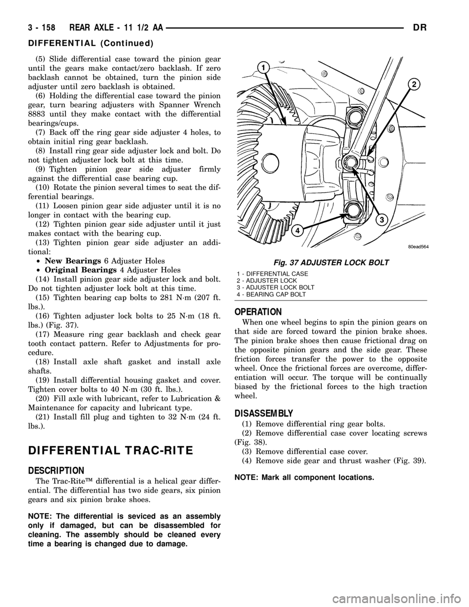
(5) Slide differential case toward the pinion gear
until the gears make contact/zero backlash. If zero
backlash cannot be obtained, turn the pinion side
adjuster until zero backlash is obtained.
(6) Holding the differential case toward the pinion
gear, turn bearing adjusters with Spanner Wrench
8883 until they make contact with the differential
bearings/cups.
(7) Back off the ring gear side adjuster 4 holes, to
obtain initial ring gear backlash.
(8) Install ring gear side adjuster lock and bolt. Do
not tighten adjuster lock bolt at this time.
(9) Tighten pinion gear side adjuster firmly
against the differential case bearing cup.
(10) Rotate the pinion several times to seat the dif-
ferential bearings.
(11) Loosen pinion gear side adjuster until it is no
longer in contact with the bearing cup.
(12) Tighten pinion gear side adjuster until it just
makes contact with the bearing cup.
(13) Tighten pinion gear side adjuster an addi-
tional:
²New Bearings6 Adjuster Holes
²Original Bearings4 Adjuster Holes
(14) Install pinion gear side adjuster lock and bolt.
Do not tighten adjuster lock bolt at this time.
(15) Tighten bearing cap bolts to 281 N´m (207 ft.
lbs.).
(16) Tighten adjuster lock bolts to 25 N´m (18 ft.
lbs.) (Fig. 37).
(17) Measure ring gear backlash and check gear
tooth contact pattern. Refer to Adjustments for pro-
cedure.
(18) Install axle shaft gasket and install axle
shafts.
(19) Install differential housing gasket and cover.
Tighten cover bolts to 40 N´m (30 ft. lbs.).
(20) Fill axle with lubricant, refer to Lubrication &
Maintenance for capacity and lubricant type.
(21) Install fill plug and tighten to 32 N´m (24 ft.
lbs.).
DIFFERENTIAL TRAC-RITE
DESCRIPTION
The Trac-RiteŸ differential is a helical gear differ-
ential. The differential has two side gears, six pinion
gears and six pinion brake shoes.
NOTE: The differential is seviced as an assembly
only if damaged, but can be disassembled for
cleaning. The assembly should be cleaned every
time a bearing is changed due to damage.
OPERATION
When one wheel begins to spin the pinion gears on
that side are forced toward the pinion brake shoes.
The pinion brake shoes then cause frictional drag on
the opposite pinion gears and the side gear. These
friction forces transfer the power to the opposite
wheel. Once the frictional forces are overcome, differ-
entiation will occur. The torque will be continually
biased by the frictional forces to the high traction
wheel.
DISASSEMBLY
(1) Remove differential ring gear bolts.
(2) Remove differential case cover locating screws
(Fig. 38).
(3) Remove differential case cover.
(4) Remove side gear and thrust washer (Fig. 39).
NOTE: Mark all component locations.
Fig. 37 ADJUSTER LOCK BOLT
1 - DIFFERENTIAL CASE
2 - ADJUSTER LOCK
3 - ADJUSTER LOCK BOLT
4 - BEARING CAP BOLT
3 - 158 REAR AXLE - 11 1/2 AADR
DIFFERENTIAL (Continued)
Page 369 of 2627

RADIATOR-3.7L/4.7L/5.7L
DESCRIPTION
The radiator is a aluminum cross-flow design with
horizontal tubes through the radiator core and verti-
cal plastic side tanks (Fig. 38).
This radiator does not contain an internal trans-
mission oil cooler.
OPERATION
The radiator supplies sufficient heat transfer using
the cooling fins interlaced between the horizontal
tubes in the radiator core to cool the engine.
DIAGNOSIS AND TESTING - RADIATOR
COOLANT FLOW
Use the following procedure to determine if coolant
is flowing through the cooling system.
(1) Idle engine until operating temperature is
reached. If the upper radiator hose is warm to the
touch, the thermostat is opening and coolant is flow-
ing to the radiator.
WARNING: HOT, PRESSURIZED COOLANT CAN
CAUSE INJURY BY SCALDING. USING A RAG TO
COVER THE RADIATOR PRESSURE CAP, OPEN
RADIATOR CAP SLOWLY TO THE FIRST STOP. THIS
WILL ALLOW ANY BUILT-UP PRESSURE TO VENT
TO THE RESERVE/OVERFLOW TANK. AFTER PRES-
SURE BUILD-UP HAS BEEN RELEASED, REMOVE
CAP FROM FILLER NECK.
(2) Drain a small amount of coolant from the radi-
ator until the ends of the radiator tubes are visible
through the filler neck. Idle the engine at normal
operating temperature. If coolant is flowing past the
exposed tubes, the coolant is circulating.
REMOVAL
(1) Disconnect battery negative cables.
WARNING: DO NOT REMOVE THE CYLINDER
BLOCK DRAIN PLUGS OR LOOSEN THE RADIATOR
DRAINCOCK WITH THE SYSTEM HOT AND UNDER
PRESSURE. SERIOUS BURNS FROM THE COOL-
ANT CAN OCCUR.
(2) Drain the cooling system (Refer to 7 - COOL-
ING - STANDARD PROCEDURE).
WARNING: CONSTANT TENSION HOSE CLAMPS
ARE USED ON MOST COOLING SYSTEM HOSES.
WHEN REMOVING OR INSTALLING, USE ONLY
TOOLS DESIGNED FOR SERVICING THIS TYPE OF
CLAMP. ALWAYS WEAR SAFETY GLASSES WHEN
SERVICING CONSTANT TENSION CLAMPS.CAUTION: A number or letter is stamped into the
tongue of constant tension clamps. If replacement
is necessary, use only an original equipment clamp
with a matching number or letter and the correct
width.
(3) Remove the hose clamps and hoses from radia-
tor.
(4) Remove the coolant reserve/overflow tank hose
from the radiator filler neck.
(5) Remove the coolant reserve/overflow tank from
the fan shroud (pull straight up). The tank slips into
slots on the fan shroud.
(6) Unclip the power steering hoses from the fan
shroud.
(7) Disconnect the electrical connectors at the
windshield washer reservoir tank and remove the
tank.
(8) Remove the fan shroud mounting bolts and pull
up and out of the radiator tank clips (Fig. 36). Posi-
tion shroud rearward over the fan blades towards
engine.
(9) Disconnect the transmission cooler lines from
the transmission cooler, then plug the transmission
lines and cooler to prevent leakage.
(10) Disconnect the power steering lines from the
power steering cooler, then plug the power steering
lines and cooler to prevent leakage.
Fig. 36 Fan Shroud - Gas Engine
1 - RADIATOR
2 - SCREWS
3 - FAN SHROUD
4 - SLIDE MOUNT
7 - 54 ENGINEDR
Page 384 of 2627
OPERATION
The transmission oil is routed through the main
cooler first, then the auxiliary cooler where addi-
tional heat is removed from the transmission oil
before returning to the transmission. The auxiliary
cooler has an internal thermostat that controls fluid
flow through the cooler. When the transmission fluid
is cold (less then operating temperature), the fluid is
routed through the cooler bypass. When the trans-
mission fluid reaches operating temperatures and
above, the thermostat closes off the bypass allowing
fluid flow through the cooler. The thermostat is ser-
vicable.
REMOVAL
REMOVAL - AIR TO OIL COOLER
(1) Remove Charge Air Cooler (Refer to 11 -
EXHAUST SYSTEM/TURBOCHARGER SYSTEM/
CHARGE AIR COOLER AND PLUMBING -
REMOVAL).
(2) Place a drain pan under the oil cooler.
(3) Raise the vehicle.
(4) Disconnect the oil cooler quick-connect fittings
from the transmission lines.
(5) Remove the charge air cooler-to-oil cooler bolt
(Fig. 5).
(6) Remove two mounting nuts.
(7) Remove the oil cooler and line assembly
towards the front of vehicle. Cooler must be rotated
and tilted into position while removing.
REMOVAL - WATER TO OIL COOLER
CAUTION: If a leak should occur in the water-to-oil
cooler mounted to the side of the engine block,
engine coolant may become mixed with transmis-
sion fluid. Transmission fluid may also enter engine
cooling system. Both cooling system and transmis-
sion should be drained and inspected in case of oil
cooler leakage.
(1) Disconnect both battery negative cables.
(2) Remove starter (Refer to 8 - ELECTRICAL/
STARTING/STARTER MOTOR - REMOVAL).
(3) Drain cooling system (Refer to 7 - COOLING -
STANDARD PROCEDURE).
(4) Disconnect coolant lines from cooler.
(5) Disconnect transmission oil lines from cooler.
Plug cooler lines to prevent oil leakage.
(6) Remove cooler bracket to transmission adapter
bolt.
(7) Remove two cooler bracket to block bolts.
(8) Remove cooler assembly from vehicle. (Fig. 6)
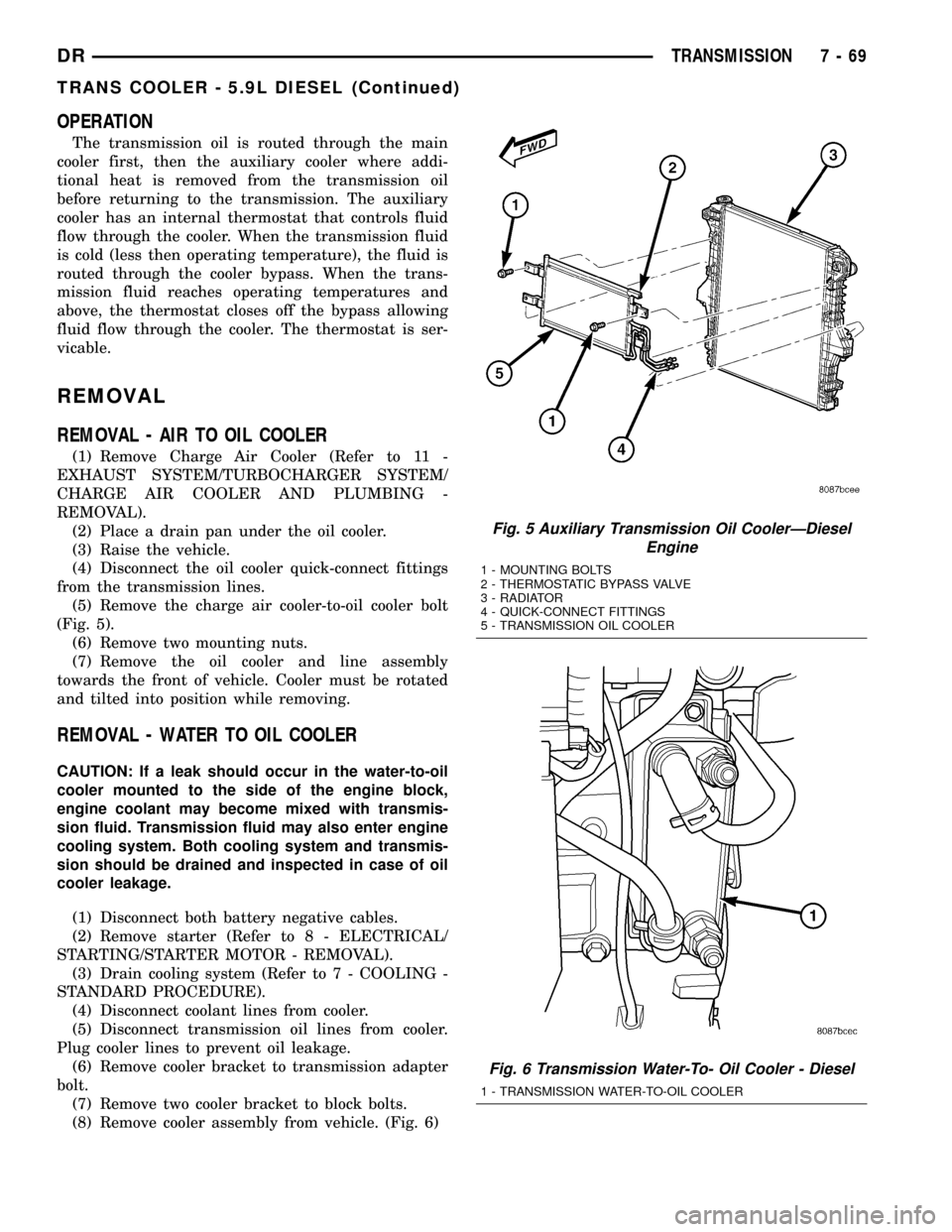
Fig. 5 Auxiliary Transmission Oil CoolerÐDiesel
Engine
1 - MOUNTING BOLTS
2 - THERMOSTATIC BYPASS VALVE
3 - RADIATOR
4 - QUICK-CONNECT FITTINGS
5 - TRANSMISSION OIL COOLER
Fig. 6 Transmission Water-To- Oil Cooler - Diesel
1 - TRANSMISSION WATER-TO-OIL COOLER
DRTRANSMISSION 7 - 69
TRANS COOLER - 5.9L DIESEL (Continued)
Page 705 of 2627
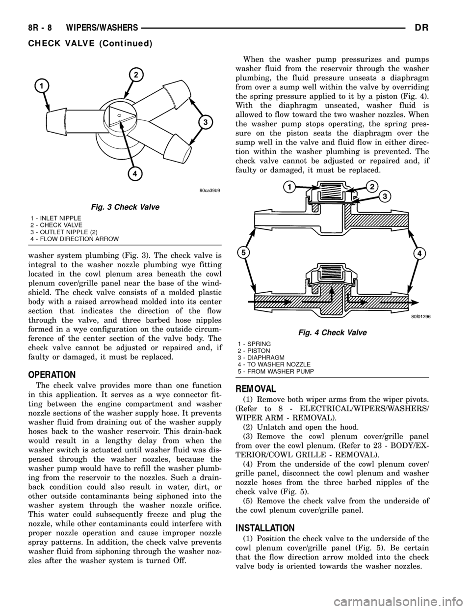
washer system plumbing (Fig. 3). The check valve is
integral to the washer nozzle plumbing wye fitting
located in the cowl plenum area beneath the cowl
plenum cover/grille panel near the base of the wind-
shield. The check valve consists of a molded plastic
body with a raised arrowhead molded into its center
section that indicates the direction of the flow
through the valve, and three barbed hose nipples
formed in a wye configuration on the outside circum-
ference of the center section of the valve body. The
check valve cannot be adjusted or repaired and, if
faulty or damaged, it must be replaced.
OPERATION
The check valve provides more than one function
in this application. It serves as a wye connector fit-
ting between the engine compartment and washer
nozzle sections of the washer supply hose. It prevents
washer fluid from draining out of the washer supply
hoses back to the washer reservoir. This drain-back
would result in a lengthy delay from when the
washer switch is actuated until washer fluid was dis-
pensed through the washer nozzles, because the
washer pump would have to refill the washer plumb-
ing from the reservoir to the nozzles. Such a drain-
back condition could also result in water, dirt, or
other outside contaminants being siphoned into the
washer system through the washer nozzle orifice.
This water could subsequently freeze and plug the
nozzle, while other contaminants could interfere with
proper nozzle operation and cause improper nozzle
spray patterns. In addition, the check valve prevents
washer fluid from siphoning through the washer noz-
zles after the washer system is turned Off.When the washer pump pressurizes and pumps
washer fluid from the reservoir through the washer
plumbing, the fluid pressure unseats a diaphragm
from over a sump well within the valve by overriding
the spring pressure applied to it by a piston (Fig. 4).
With the diaphragm unseated, washer fluid is
allowed to flow toward the two washer nozzles. When
the washer pump stops operating, the spring pres-
sure on the piston seats the diaphragm over the
sump well in the valve and fluid flow in either direc-
tion within the washer plumbing is prevented. The
check valve cannot be adjusted or repaired and, if
faulty or damaged, it must be replaced.REMOVAL
(1) Remove both wiper arms from the wiper pivots.
(Refer to 8 - ELECTRICAL/WIPERS/WASHERS/
WIPER ARM - REMOVAL).
(2) Unlatch and open the hood.
(3) Remove the cowl plenum cover/grille panel
from over the cowl plenum. (Refer to 23 - BODY/EX-
TERIOR/COWL GRILLE - REMOVAL).
(4) From the underside of the cowl plenum cover/
grille panel, disconnect the cowl plenum and washer
nozzle hoses from the three barbed nipples of the
check valve (Fig. 5).
(5) Remove the check valve from the underside of
the cowl plenum cover/grille panel.
INSTALLATION
(1) Position the check valve to the underside of the
cowl plenum cover/grille panel (Fig. 5). Be certain
that the flow direction arrow molded into the check
valve body is oriented towards the washer nozzles.
Fig. 3 Check Valve
1 - INLET NIPPLE
2 - CHECK VALVE
3 - OUTLET NIPPLE (2)
4 - FLOW DIRECTION ARROW
Fig. 4 Check Valve
1 - SPRING
2 - PISTON
3 - DIAPHRAGM
4 - TO WASHER NOZZLE
5 - FROM WASHER PUMP
8R - 8 WIPERS/WASHERSDR
CHECK VALVE (Continued)
Page 746 of 2627

8W-10 POWER DISTRIBUTION
Component Page
A/C Compressor Clutch....................8W-10-17, 40
A/C Compressor Clutch Relay.................8W-10-17, 40
A/C-Heater Control....................8W-10-42, 43, 49
Adjustable Pedal Relay....................8W-10-15, 32
Adjustable Pedal Switch..................8W-10-15, 32, 42
Airbag Control Module.....................8W-10-42, 44
Airbag-Passenger On/Off Switch.................8W-10-42
Ambient Temperature Sensor.................8W-10-48, 50
Amplifier Audio..........................8W-10-31
Ashtray Lamp...........................8W-10-35
Auto Shut Down Relay....................8W-10-12, 19
Automatic Day/Night Mirror.................8W-10-41, 48
Auxiliary Battery.........................8W-10-12
Backup Lamp Switch.....................8W-10-44, 49
Battery.............................8W-10-12, 19
Blower Motor............................8W-10-52
Brake Lamp Switch....................8W-10-14, 30, 40
Capacitor..............................8W-10-22
Cigar Lighter Outlet........................8W-10-46
Circuit Breaker...........................8W-10-52
Clearance Lamp No. 1.......................8W-10-35
Clearance Lamp No. 2.......................8W-10-35
Clearance Lamp No. 3.......................8W-10-35
Clearance Lamp No. 4.......................8W-10-35
Clearance Lamp No. 5.......................8W-10-35
Clutch Interlock Brake Switch..................8W-10-37
Coil On Plug No. 1.......................8W-10-20, 23
Coil On Plug No. 2.......................8W-10-21, 22
Coil On Plug No. 3.......................8W-10-20, 23
Coil On Plug No. 4.......................8W-10-21, 22
Coil On Plug No. 5.......................8W-10-20, 23
Coil On Plug No. 6.......................8W-10-21, 22
Coil On Plug No. 7.......................8W-10-20, 23
Coil On Plug No. 8.......................8W-10-21, 22
Compass/Mini-Trip Computer...............8W-10-31, 39, 41
Condenser Fan.........................8W-10-18, 45
Condenser Fan Relay.....................8W-10-18, 45
Controller Antilock Brake.................8W-10-14, 28, 44
Data Link Connector......................8W-10-30, 50
Door Lock Switch-Passenger....................8W-10-41
Driver Door Module....................8W-10-15, 32, 52
Electric Backlight.........................8W-10-49
Electric Brake Provision....................8W-10-12, 19
Engine Control Module................8W-10-12, 26, 38, 40
Fender Lamp-Front Left......................8W-10-35
Fender Lamp-Front Right.....................8W-10-35
Fender Lamp-Rear Left......................8W-10-35
Fender Lamp-Rear Right.....................8W-10-35
Fog Lamp Relay........................8W-10-16, 36
Fog Lamp-Left...........................8W-10-36
Fog Lamp-Right..........................8W-10-36
Front Control Module . 8W-10-13, 26, 29, 30, 32, 33, 34, 36, 47, 48, 50, 51
Fuel Heater............................8W-10-53
Fuel Heater Relay.....................8W-10-18, 40, 53
Fuel Injector No. 1.......................8W-10-23, 24
Fuel Injector No. 2.......................8W-10-21, 22
Fuel Injector No. 3.......................8W-10-23, 24
Fuel Injector No. 4.......................8W-10-21, 22
Fuel Injector No. 5.......................8W-10-23, 24
Fuel Injector No. 6.......................8W-10-21, 22
Fuel Injector No. 7.......................8W-10-23, 24
Fuel Injector No. 8.......................8W-10-21, 22
Fuel Pump Module.......................8W-10-17, 39
Fuel Pump Relay......................8W-10-17, 39, 40
Fuse 1.............................8W-10-12, 19
Fuse 2...........................8W-10-12, 13, 19
Fuse 3.............................8W-10-13, 25
Fuse 4.............................8W-10-13, 25
Fuse 5.......................8W-10-12, 13, 14, 26, 27
Fuse 6...........................8W-10-13, 14, 28
Fuse 7.............................8W-10-14, 28
Fuse 8.............................8W-10-15, 29
Fuse 9.............................8W-10-13, 25
Fuse 10.............................8W-10-13, 25
Fuse 11...........................8W-10-13, 14, 30
Fuse 12...........................8W-10-18, 45, 53
Fuse 13.............................8W-10-13, 30
Fuse 14.............................8W-10-15, 37
Fuse 15...........................8W-10-16, 17, 34
Fuse 16.............................8W-10-17, 40
Fuse 17...........................8W-10-17, 18, 39
Fuse 18.............................8W-10-14, 30
Fuse 19.............................8W-10-14, 31
Fuse 20.............................8W-10-13, 25
Fuse 21.............................8W-10-14, 31
Fuse 22.............................8W-10-14, 31
Fuse 23.............................8W-10-14, 31
Fuse 24.............................8W-10-14, 30Component Page
Fuse 25.............................8W-10-14, 31
Fuse 26...............................8W-10-49
Fuse 27...........................8W-10-17, 18, 43
Fuse 28.............................8W-10-40, 41
Fuse 29...............................8W-10-46
Fuse 32.............................8W-10-17, 34
Fuse 33.............................8W-10-17, 34
Fuse 34.............................8W-10-17, 34
Fuse 35...............................8W-10-44
Fuse 36...............................8W-10-43
Fuse 37...............................8W-10-44
Fuse 38.............................8W-10-43, 44
Fuse 40...........................8W-10-15, 16, 32
Fuse 41.............................8W-10-16, 36
Fuse 42.............................8W-10-14, 32
Fuse 43.............................8W-10-14, 32
Fuse 45...........................8W-10-16, 17, 36
Fuse 46...........................8W-10-15, 16, 33
Fuse 47.............................8W-10-16, 33
Fuse 48.............................8W-10-15, 32
Fuse 49.............................8W-10-12, 19
Fuse 50.............................8W-10-26, 40
Fuse 51...........................8W-10-14, 15, 30
Fuse 52.............................8W-10-43, 44
Fuse 53...............................8W-10-41
Fusible Link............................8W-10-12
G104........................8W-10-27, 29, 47, 48, 53
G201................................8W-10-25
Generator..............................8W-10-12
Headlamp Switch.........................8W-10-36
Headlamp-Left...........................8W-10-51
Headlamp-Right..........................8W-10-51
Heated Mirror Relay......................8W-10-18, 43
Horn Relay...........................8W-10-16, 36
Horn-High Note..........................8W-10-36
Horn-Low Note...........................8W-10-36
Ignition Switch...............8W-10-13, 25, 37, 41, 44, 46, 52
Instrument Cluster............8W-10-14, 25, 30, 31, 41, 46, 52
Integrated Power Module . . 8W-10-3, 4, 12, 13, 14, 15, 16, 17, 18, 19, 25,
26, 27, 28, 29, 30, 31, 32, 33, 34, 36, 37, 39, 40, 41, 42, 43, 44, 45, 46,
47, 48, 49, 50, 51, 53
License Lamp-Left.........................8W-10-34
License Lamp-Right........................8W-10-34
Oxygen Sensor Downstream Relay..............8W-10-12, 19
Park Lamp Relay.......................8W-10-17, 34
Park/Turn Signal Lamp-Left Front..............8W-10-34, 47
Park/Turn Signal Lamp-Right Front.............8W-10-34, 47
Passenger Lumbar Switch.....................8W-10-28
Power Mirror-Left.........................8W-10-43
Power Mirror-Right........................8W-10-43
Power Outlet..........................8W-10-14, 31
Power Outlet-Console.....................8W-10-14, 32
Power Seat Switch-Driver.....................8W-10-28
Power Seat Switch-Passenger...................8W-10-28
Power Window Circuit Breaker..................8W-10-52
Powertrain Control Module . . 8W-10-18, 19, 22, 27, 31, 37, 39, 40, 45, 52
PTCNo.1 .........................8W-10-39, 40, 41
PTCNo.2 .............................8W-10-46
PTCNo.5 .............................8W-10-33
Radio..............................8W-10-30, 46
Rear Window Defogger Relay...................8W-10-49
Seat Belt Tensioner Reducer....................8W-10-46
Seat Heater Interface Module...................8W-10-32
Sentry Key Immobilizer Module..............8W-10-31, 39, 40
Starter Motor..........................8W-10-15, 37
Starter Motor Relay......................8W-10-15, 37
Tail/Stop/Turn Signal Lamp-Left...........8W-10-34, 47, 48, 50
Tail/Stop/Turn Signal Lamp-Right..........8W-10-35, 47, 48, 50
Tailgate Lamp...........................8W-10-34
Trailer Tow Connector.................8W-10-16, 17, 33, 34
Trailer Tow Connector-Add On..........8W-10-14, 31, 33, 34, 48
Trailer Tow Left Turn Relay..................8W-10-16, 33
Trailer Tow Right Turn Relay.................8W-10-16, 33
Transfer Case Control Module...............8W-10-14, 32, 37
Transfer Case Selector Switch...................8W-10-41
Transmission Control Relay................8W-10-13, 26, 27
Transmission Range Sensor................8W-10-38, 44, 49
Transmission Solenoid Assembly.................8W-10-26
Transmission Solenoid/TRS Assembly...........8W-10-27, 44, 49
Underhood Lamp..........................8W-10-30
Vistronic Fan Drive........................8W-10-43
Washer Fluid Level Switch....................8W-10-48
Washer Pump Motor-Front....................8W-10-48
Wiper High/Low Relay.....................8W-10-15, 29
Wiper Motor-Front.......................8W-10-29, 48
Wiper On/Off Relay......................8W-10-15, 29
DR8W-10 POWER DISTRIBUTION 8W - 10 - 1
Page 832 of 2627

8W-30 FUEL/IGNITION SYSTEM
Component Page
A/C Compressor Clutch Relay............ 8W-30-9, 58
A/C Pressure Transducer......... 8W-30-23, 28, 29, 45
Accelerator Pedal Position Sensor . . . 8W-30-29, 47, 64, 65
Adjustable Pedal Motor................. 8W-30-61
Adjustable Pedal Relay.................. 8W-30-61
Adjustable Pedal Switch................. 8W-30-61
Ambient Temperature Sensor............. 8W-30-30
Auto Shut Down Relay................... 8W-30-4
Battery............................ 8W-30-52
Battery Temperature Sensor............ 8W-30-12, 56
Brake Lamp Switch............. 8W-30-8, 36, 57, 63
Camshaft Position Sensor........ 8W-30-10, 29, 45, 46
Capacitor........................... 8W-30-13
Clockspring..................... 8W-30-8, 36, 59
Coil On Plug No. 1.................. 8W-30-14, 39
Coil On Plug No. 2.................. 8W-30-15, 37
Coil On Plug No. 3.................. 8W-30-14, 39
Coil On Plug No. 4.................. 8W-30-15, 37
Coil On Plug No. 5.................. 8W-30-16, 39
Coil On Plug No. 6.................. 8W-30-13, 37
Coil On Plug No. 7.................. 8W-30-16, 39
Coil On Plug No. 8.................. 8W-30-13, 37
Condenser Fan Relay.................... 8W-30-9
Controller Antilock Brake............ 8W-30-6, 11, 57
Crankshaft Position Sensor............ 8W-30-10, 46
Data Link Connector............... 8W-30-9, 22, 55
Data Link Connector-Engine.............. 8W-30-51
EGR Solenoid................... 8W-30-28, 29, 32
Electronic Throttle Control Module.......... 8W-30-35
Engine Control Module....... 8W-30-42, 43, 44, 45, 46,
47, 48, 49, 50, 51, 52, 53, 54,
55, 56, 57, 58, 59, 60, 62, 63, 64, 65
Engine Coolant Temperature Sensor.... 8W-30-23, 41, 47
Engine Oil Pressure Switch.......... 8W-30-2, 53, 56
EVAP/Purge Solenoid................... 8W-30-12
Front Control Module................... 8W-30-61
Fuel Control Actuator................... 8W-30-50
Fuel Heater......................... 8W-30-60
Fuel Heater Relay..................... 8W-30-60
Fuel Injector No. 1.................. 8W-30-14, 40
Fuel Injector No. 2.................. 8W-30-15, 38
Fuel Injector No. 3.................. 8W-30-14, 40
Fuel Injector No. 4.................. 8W-30-15, 38
Fuel Injector No. 5.................. 8W-30-14, 40
Fuel Injector No. 6.................. 8W-30-15, 38
Fuel Injector No. 7.................. 8W-30-16, 40
Fuel Injector No. 8.................. 8W-30-13, 38
Fuel Injector Pack No. 1................. 8W-30-42
Fuel Injector Pack No. 2............ 8W-30-42, 43, 44
Fuel Injector Pack No. 3................. 8W-30-44
Fuel Pump Module................... 8W-30-3, 58
Fuel Pump Motor...................... 8W-30-48
Fuel Pump Relay....................... 8W-30-3
Fuse 2.............................. 8W-30-4
Fuse 5........................... 8W-30-25, 62
Fuse 12............................ 8W-30-60
Fuse 17............................. 8W-30-3
Fuse 19............................ 8W-30-52
Fuse 23............................. 8W-30-2Component Page
Fuse 36.......................... 8W-30-54, 61
Fuse 40............................ 8W-30-61
Fuse 49............................. 8W-30-4
Fuse 50..................... 8W-30-2, 55, 58, 62
Fusible Link......................... 8W-30-52
G104........................ 8W-30-3, 8, 25, 60
G105............................ 8W-30-56, 58
G107........... 8W-30-2, 7, 15, 18, 19, 20, 21, 30, 32
G114 .............................. 8W-30-53
G120............................ 8W-30-51, 60
G201............................... 8W-30-6
G202.............................. 8W-30-61
Generator......................... 8W-30-7, 51
Idle Air Control Motor................... 8W-30-9
Ignition Switch..................... 8W-30-6, 22
Inlet Air Temperature Sensor............. 8W-30-49
Input Speed Sensor.................... 8W-30-24
Instrument Cluster.................... 8W-30-30
Intake Air Heater Relay No. 1............. 8W-30-56
Intake Air Heater Relay No. 2............. 8W-30-56
Intake Air Temperature Sensor.......... 8W-30-23, 41
Intake Air Temperature/Manifold Absolute
Pressure Sensor..................... 8W-30-50
Integrated Power Module.... 8W-30-2, 3, 4, 9, 25, 52, 54,
55, 58, 60, 61, 62, 64
Knock Sensor........................ 8W-30-31
Knock Sensor-Left..................... 8W-30-33
Knock Sensor-Right.................... 8W-30-33
Lift Pump Motor...................... 8W-30-51
Line Pressure Sensor................... 8W-30-17
Manifold Absolute Pressure Sensor..... 8W-30-23, 29, 41
Natural Vacuum Leak Detection Assembly..... 8W-30-7
Output Speed Sensor................. 8W-30-24, 62
Oxygen Sensor 1/1 Upstream........... 8W-30-20, 21
Oxygen Sensor 1/2 Downstream......... 8W-30-18, 19
Oxygen Sensor 2/1 Upstream........... 8W-30-20, 21
Oxygen Sensor 2/2 Downstream......... 8W-30-18, 19
Oxygen Sensor Downstream Relay........... 8W-30-4
Power Steering Pressure Switch............ 8W-30-7
Powertrain Control Module....... 8W-30-2, 3, 4, 5, 6, 7,
8, 9, 10, 11, 12, 13, 14, 15, 16,
17, 18, 19, 20, 21, 22, 23, 24,
25, 26, 27, 28, 29, 30, 31, 32,
33, 35, 36, 37, 38, 39, 40, 41
PTCNo.1 ....................... 8W-30-3, 9, 58
Pto Switch........................... 8W-30-6
Speed Control Servo.................. 8W-30-8, 63
Speed Control Switch-Left............. 8W-30-36, 59
Speed Control Switch-Right............ 8W-30-36, 59
Starter Motor Relay.................. 8W-30-2, 64
Throttle Position Sensor................. 8W-30-17
Tow/Haul Overdrive Switch............. 8W-30-6, 64
Transmission Control Relay............ 8W-30-25, 62
Transmission Range Sensor............... 8W-30-64
Transmission Solenoid Assembly......... 8W-30-54, 62
Transmission Solenoid/TRS Assembly . 8W-30-5, 25, 26, 27
Vacuum Pump........................ 8W-30-58
Vistronic Fan Drive.................... 8W-30-54
Water In Fuel Sensor................ 8W-30-47, 48
DR8W-30 FUEL/IGNITION SYSTEM 8W - 30 - 1