automatic transmission fluid type DODGE RAM 1500 1998 2.G User Guide
[x] Cancel search | Manufacturer: DODGE, Model Year: 1998, Model line: RAM 1500, Model: DODGE RAM 1500 1998 2.GPages: 2627
Page 1869 of 2627
(33) Remove tools and remove servo piston and
spring.
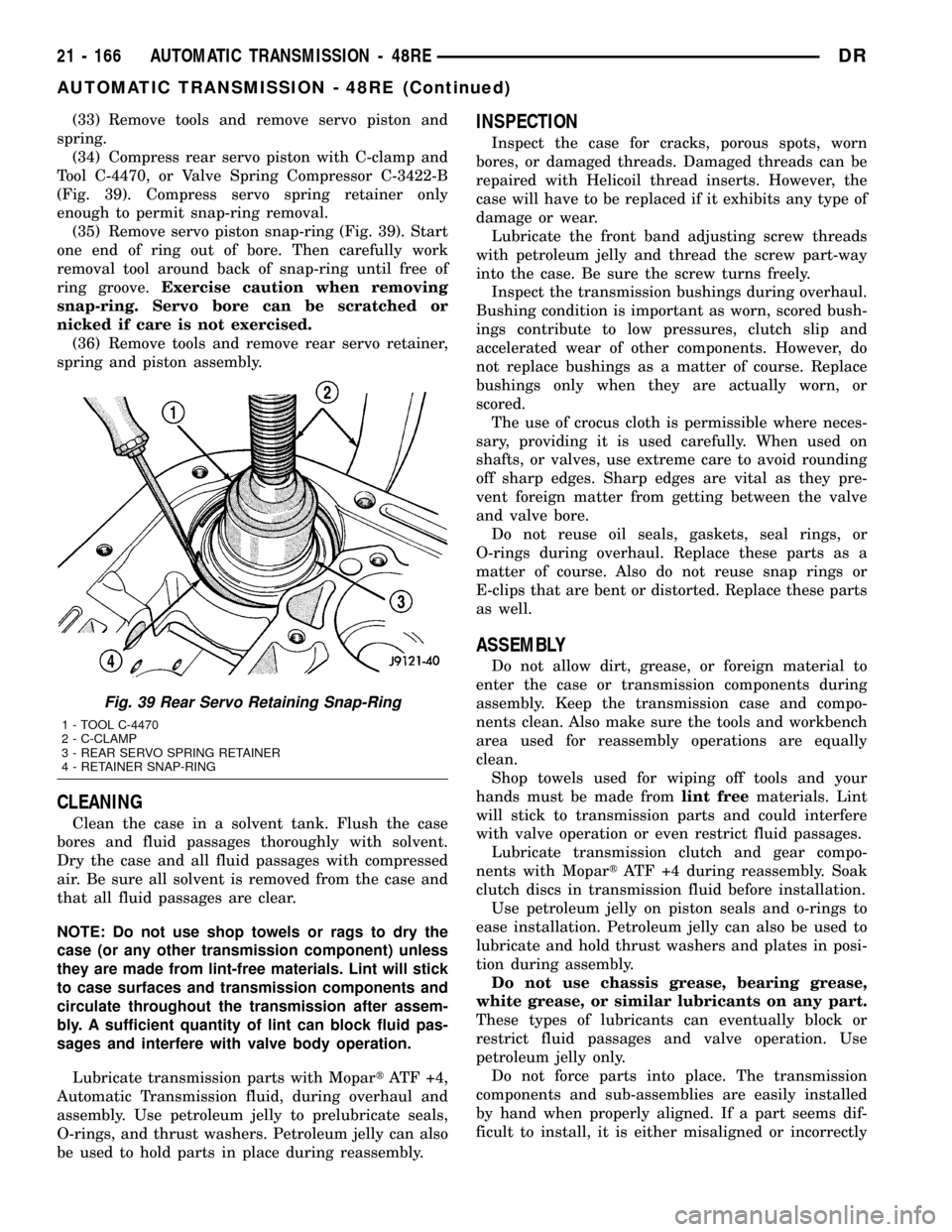
(34) Compress rear servo piston with C-clamp and
Tool C-4470, or Valve Spring Compressor C-3422-B
(Fig. 39). Compress servo spring retainer only
enough to permit snap-ring removal.
(35) Remove servo piston snap-ring (Fig. 39). Start
one end of ring out of bore. Then carefully work
removal tool around back of snap-ring until free of
ring groove.Exercise caution when removing
snap-ring. Servo bore can be scratched or
nicked if care is not exercised.
(36) Remove tools and remove rear servo retainer,
spring and piston assembly.
CLEANING
Clean the case in a solvent tank. Flush the case
bores and fluid passages thoroughly with solvent.
Dry the case and all fluid passages with compressed
air. Be sure all solvent is removed from the case and
that all fluid passages are clear.
NOTE: Do not use shop towels or rags to dry the
case (or any other transmission component) unless
they are made from lint-free materials. Lint will stick
to case surfaces and transmission components and
circulate throughout the transmission after assem-
bly. A sufficient quantity of lint can block fluid pas-
sages and interfere with valve body operation.
Lubricate transmission parts with MopartATF +4,
Automatic Transmission fluid, during overhaul and
assembly. Use petroleum jelly to prelubricate seals,
O-rings, and thrust washers. Petroleum jelly can also
be used to hold parts in place during reassembly.
INSPECTION
Inspect the case for cracks, porous spots, worn
bores, or damaged threads. Damaged threads can be
repaired with Helicoil thread inserts. However, the
case will have to be replaced if it exhibits any type of
damage or wear.
Lubricate the front band adjusting screw threads
with petroleum jelly and thread the screw part-way
into the case. Be sure the screw turns freely.
Inspect the transmission bushings during overhaul.
Bushing condition is important as worn, scored bush-
ings contribute to low pressures, clutch slip and
accelerated wear of other components. However, do
not replace bushings as a matter of course. Replace
bushings only when they are actually worn, or
scored.
The use of crocus cloth is permissible where neces-
sary, providing it is used carefully. When used on
shafts, or valves, use extreme care to avoid rounding
off sharp edges. Sharp edges are vital as they pre-
vent foreign matter from getting between the valve
and valve bore.
Do not reuse oil seals, gaskets, seal rings, or
O-rings during overhaul. Replace these parts as a
matter of course. Also do not reuse snap rings or
E-clips that are bent or distorted. Replace these parts
as well.
ASSEMBLY
Do not allow dirt, grease, or foreign material to
enter the case or transmission components during
assembly. Keep the transmission case and compo-
nents clean. Also make sure the tools and workbench
area used for reassembly operations are equally
clean.
Shop towels used for wiping off tools and your
hands must be made fromlint freematerials. Lint
will stick to transmission parts and could interfere
with valve operation or even restrict fluid passages.
Lubricate transmission clutch and gear compo-
nents with MopartATF +4 during reassembly. Soak
clutch discs in transmission fluid before installation.
Use petroleum jelly on piston seals and o-rings to
ease installation. Petroleum jelly can also be used to
lubricate and hold thrust washers and plates in posi-
tion during assembly.
Do not use chassis grease, bearing grease,
white grease, or similar lubricants on any part.
These types of lubricants can eventually block or
restrict fluid passages and valve operation. Use
petroleum jelly only.
Do not force parts into place. The transmission
components and sub-assemblies are easily installed
by hand when properly aligned. If a part seems dif-
ficult to install, it is either misaligned or incorrectly
Fig. 39 Rear Servo Retaining Snap-Ring
1 - TOOL C-4470
2 - C-CLAMP
3 - REAR SERVO SPRING RETAINER
4 - RETAINER SNAP-RING
21 - 166 AUTOMATIC TRANSMISSION - 48REDR
AUTOMATIC TRANSMISSION - 48RE (Continued)
Page 1905 of 2627
(2) Heavy duty operation with a vehicle not prop-
erly equipped for this type of operation. Trailer tow-
ing or similar high load operation will overheat the
transmission fluid if the vehicle is improperly
equipped. Such vehicles should have an auxiliary
transmission fluid cooler, a heavy duty cooling sys-
tem, and the engine/axle ratio combination needed to
handle heavy loads.
DIAGNOSIS AND TESTING - FLUID
CONTAMINATION
Transmission fluid contamination is generally a
result of:
²adding incorrect fluid
²failure to clean dipstick and fill tube when
checking level
²engine coolant entering the fluid
²internal failure that generates debris
²overheat that generates sludge (fluid break-
down)
²failure to replace contaminated converter after
repair
The use of non-recommended fluids can result in
transmission failure. The usual results are erratic
shifts, slippage, abnormal wear and eventual failure
due to fluid breakdown and sludge formation. Avoid
this condition by using recommended fluids only.
The dipstick cap and fill tube should be wiped
clean before checking fluid level. Dirt, grease and
other foreign material on the cap and tube could fall
into the tube if not removed beforehand. Take the
time to wipe the cap and tube clean before withdraw-
ing the dipstick.
Engine coolant in the transmission fluid is gener-
ally caused by a cooler malfunction. The only remedy
is to replace the radiator as the cooler in the radiator
is not a serviceable part. If coolant has circulated
through the transmission, an overhaul is necessary.
The torque converter should also be replaced when-
ever a failure generates sludge and debris. This is
necessary because normal converter flushing proce-
dures will not remove all contaminants.
STANDARD PROCEDURE
STANDARD PROCEDURE - FLUID LEVEL
CHECK
Low fluid level can cause a variety of conditions
because it allows the pump to take in air along with
the fluid. As in any hydraulic system, air bubbles
make the fluid spongy, therefore, pressures will be
low and build up slowly.
Improper filling can also raise the fluid level too
high. When the transmssion has too much fluid, thegeartrain churns up foam and cause the same condi-
tions which occur with a low fluid level.
In either case, air bubbles can cause overheating
and/or fluid oxidation, and varnishing. This can
interfere with normal valve, clutch, and accumulator
operation. Foaming can also result in fluid escaping
from the transmission vent where it may be mis-
taken for a leak.
After the fluid has been checked, seat the dipstick
fully to seal out water and dirt.
The transmission has a dipstick to check oil level.
It is located on the right side of the engine. Be sure
to wipe all dirt from dipstick handle before removing.
Fluid level is checked with the engine running at
curb idle speed, the transmission in NEUTRAL and
the transmission fluid at normal operating tempera-
ture.The engine should be running at idle
speed for at least one minute, with the vehicle
on level ground.
The transmission fluid level can be checked two
ways.
PROCEDURE ONE
(1) Transmission fluid must be at normal operat-
ing temperature for accurate fluid level check. Drive
vehicle if necessary to bring fluid temperature up to
normal hot operating temperature of 82ÉC (180ÉF).
(2) Position vehicle on level surface.
(3) Start and run engine at curb idle speed.
(4) Apply parking brakes.
(5) Shift transmission momentarily into all gear
ranges. Then shift transmission back to NEUTRAL.
(6) Clean top of filler tube and dipstick to keep
dirt from entering tube.
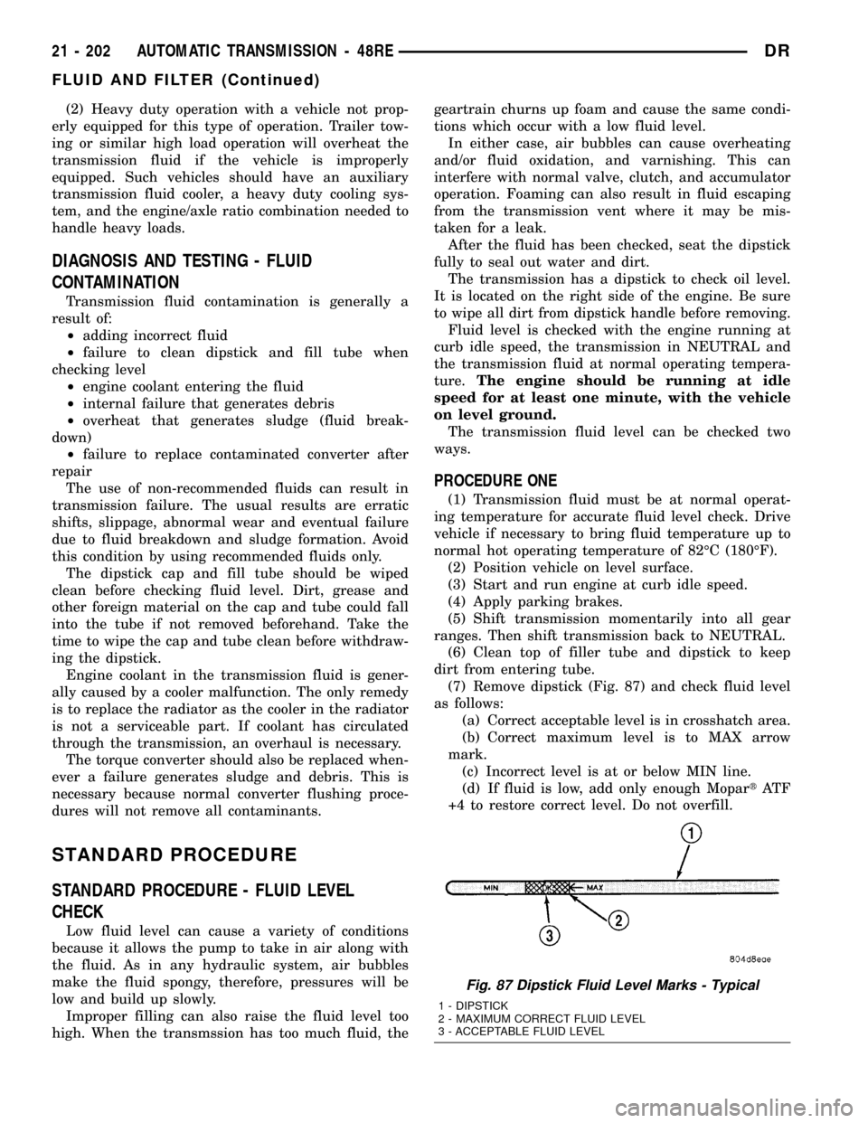
(7) Remove dipstick (Fig. 87) and check fluid level
as follows:
(a) Correct acceptable level is in crosshatch area.
(b) Correct maximum level is to MAX arrow
mark.
(c) Incorrect level is at or below MIN line.
(d) If fluid is low, add only enough MopartAT F
+4 to restore correct level. Do not overfill.
Fig. 87 Dipstick Fluid Level Marks - Typical
1 - DIPSTICK
2 - MAXIMUM CORRECT FLUID LEVEL
3 - ACCEPTABLE FLUID LEVEL
21 - 202 AUTOMATIC TRANSMISSION - 48REDR
FLUID AND FILTER (Continued)
Page 1910 of 2627
Inspect the piston and retainer seal surfaces for
nicks or scratches. Minor scratches can be removed
with crocus cloth. However, replace the piston and/or
retainer if the seal surfaces are seriously scored.
Check the clutch piston check ball. The ball should
be securely in place. Replace the piston if the ball is
missing, or seized in place.
ASSEMBLY
NOTE: The 48RE transmission uses five plates and
discs for the front clutch.
(1) Soak clutch discs in transmission fluid.
(2) Install new inner piston seal onto the outer
diameter of the clutch retainer inner hub.
(3)
Install new outer seal onto the clutch piston. Be
sure seal lips of both seals face the interior of the
retainer.
(4) Lubricate new inner and outer piston seals
with petroleum jelly.
(5) Install clutch piston in retainer. Use twisting
motion to seat piston in bottom of retainer. A thin
strip of plastic (about 0.015 - 0.020 in. thick), can be
used to guide seals into place if necessary.
CAUTION: Never push the clutch piston straight in.
This will fold the seals over causing leakage and
clutch slip. In addition, never use any type of metaltool to help ease the piston seals into place. Metal
tools will cut, shave, or score the seals.
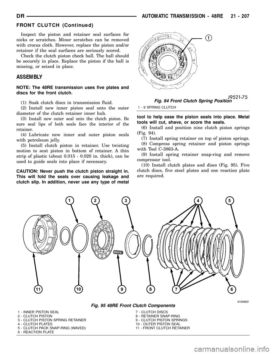
(6) Install and position nine clutch piston springs
(Fig. 94).
(7) Install spring retainer on top of piston springs.
(8) Compress spring retainer and piston springs
with Tool C-3863-A.
(9) Install spring retainer snap-ring and remove
compressor tool.
(10) Install clutch plates and discs (Fig. 95). Five
clutch discs, five steel plates and one reaction plate
are required.
Fig. 94 Front Clutch Spring Position
1 - 9 SPRING CLUTCH
Fig. 95 48RE Front Clutch Components
1 - INNER PISTON SEAL 7 - CLUTCH DISCS
2 - CLUTCH PISTON 8 - RETAINER SNAP-RING
3 - CLUTCH PISTON SPRING RETAINER 9 - CLUTCH PISTON SPRINGS
4 - CLUTCH PLATES 10 - OUTER PISTON SEAL
5 - CLUTCH PACK SNAP-RING (WAVED) 11 - FRONT CLUTCH RETAINER
6 - REACTION PLATE
DRAUTOMATIC TRANSMISSION - 48RE 21 - 207
FRONT CLUTCH (Continued)
Page 1942 of 2627
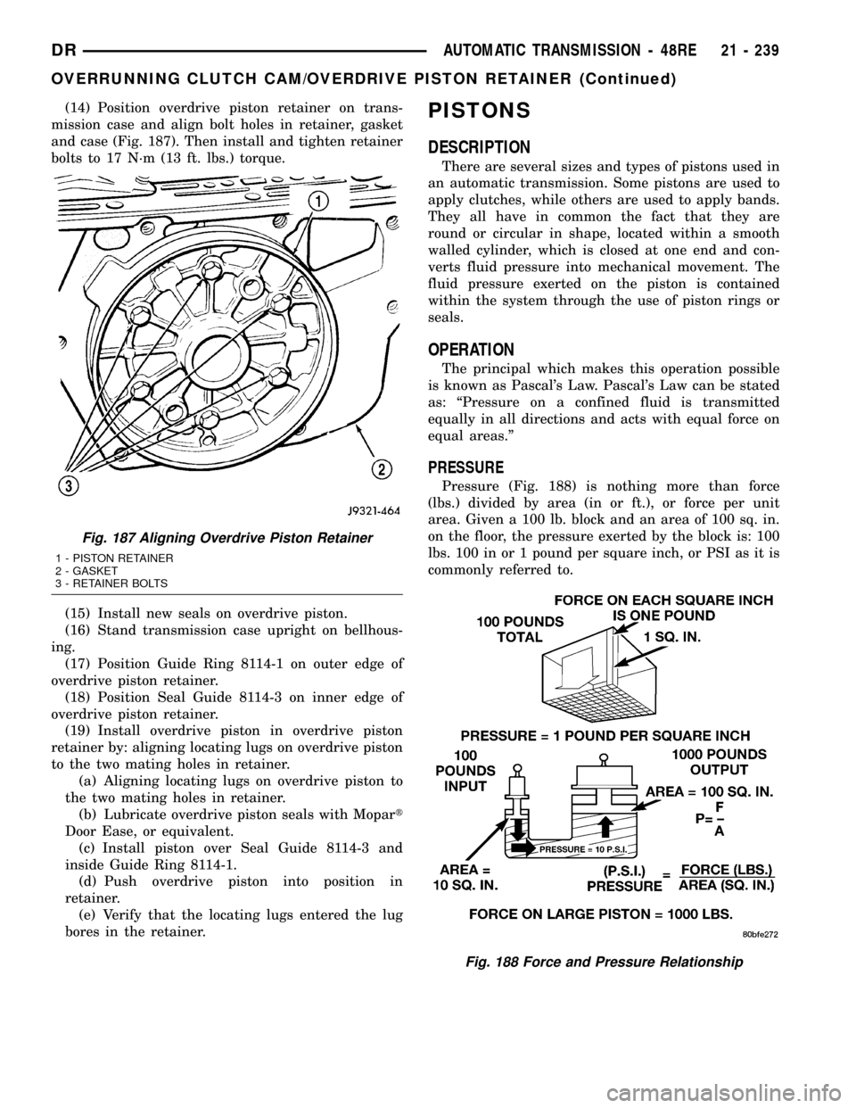
(14) Position overdrive piston retainer on trans-
mission case and align bolt holes in retainer, gasket
and case (Fig. 187). Then install and tighten retainer
bolts to 17 N´m (13 ft. lbs.) torque.
(15) Install new seals on overdrive piston.
(16) Stand transmission case upright on bellhous-
ing.
(17) Position Guide Ring 8114-1 on outer edge of
overdrive piston retainer.
(18) Position Seal Guide 8114-3 on inner edge of
overdrive piston retainer.
(19) Install overdrive piston in overdrive piston
retainer by: aligning locating lugs on overdrive piston
to the two mating holes in retainer.
(a) Aligning locating lugs on overdrive piston to
the two mating holes in retainer.
(b) Lubricate overdrive piston seals with Mopart
Door Ease, or equivalent.
(c) Install piston over Seal Guide 8114-3 and
inside Guide Ring 8114-1.
(d) Push overdrive piston into position in
retainer.
(e) Verify that the locating lugs entered the lug
bores in the retainer.PISTONS
DESCRIPTION
There are several sizes and types of pistons used in
an automatic transmission. Some pistons are used to
apply clutches, while others are used to apply bands.
They all have in common the fact that they are
round or circular in shape, located within a smooth
walled cylinder, which is closed at one end and con-
verts fluid pressure into mechanical movement. The
fluid pressure exerted on the piston is contained
within the system through the use of piston rings or
seals.
OPERATION
The principal which makes this operation possible
is known as Pascal's Law. Pascal's Law can be stated
as: ªPressure on a confined fluid is transmitted
equally in all directions and acts with equal force on
equal areas.º
PRESSURE
Pressure (Fig. 188) is nothing more than force
(lbs.) divided by area (in or ft.), or force per unit
area. Given a 100 lb. block and an area of 100 sq. in.
on the floor, the pressure exerted by the block is: 100
lbs. 100 in or 1 pound per square inch, or PSI as it is
commonly referred to.
Fig. 187 Aligning Overdrive Piston Retainer
1 - PISTON RETAINER
2 - GASKET
3 - RETAINER BOLTS
Fig. 188 Force and Pressure Relationship
DRAUTOMATIC TRANSMISSION - 48RE 21 - 239
OVERRUNNING CLUTCH CAM/OVERDRIVE PISTON RETAINER (Continued)
Page 1952 of 2627
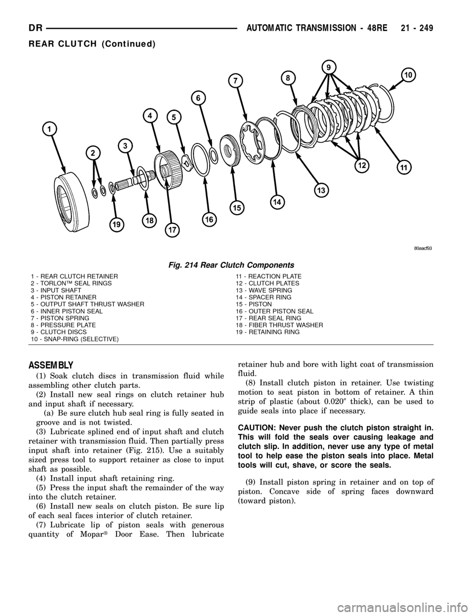
ASSEMBLY
(1) Soak clutch discs in transmission fluid while
assembling other clutch parts.
(2) Install new seal rings on clutch retainer hub
and input shaft if necessary.
(a) Be sure clutch hub seal ring is fully seated in
groove and is not twisted.
(3) Lubricate splined end of input shaft and clutch
retainer with transmission fluid. Then partially press
input shaft into retainer (Fig. 215). Use a suitably
sized press tool to support retainer as close to input
shaft as possible.
(4) Install input shaft retaining ring.
(5) Press the input shaft the remainder of the way
into the clutch retainer.
(6) Install new seals on clutch piston. Be sure lip
of each seal faces interior of clutch retainer.
(7) Lubricate lip of piston seals with generous
quantity of MopartDoor Ease. Then lubricateretainer hub and bore with light coat of transmission
fluid.
(8) Install clutch piston in retainer. Use twisting
motion to seat piston in bottom of retainer. A thin
strip of plastic (about 0.0209thick), can be used to
guide seals into place if necessary.
CAUTION: Never push the clutch piston straight in.
This will fold the seals over causing leakage and
clutch slip. In addition, never use any type of metal
tool to help ease the piston seals into place. Metal
tools will cut, shave, or score the seals.
(9) Install piston spring in retainer and on top of
piston. Concave side of spring faces downward
(toward piston).
Fig. 214 Rear Clutch Components
1 - REAR CLUTCH RETAINER 11 - REACTION PLATE
2 - TORLONŸ SEAL RINGS 12 - CLUTCH PLATES
3 - INPUT SHAFT 13 - WAVE SPRING
4 - PISTON RETAINER 14 - SPACER RING
5 - OUTPUT SHAFT THRUST WASHER 15 - PISTON
6 - INNER PISTON SEAL 16 - OUTER PISTON SEAL
7 - PISTON SPRING 17 - REAR SEAL RING
8 - PRESSURE PLATE 18 - FIBER THRUST WASHER
9 - CLUTCH DISCS 19 - RETAINING RING
10 - SNAP-RING (SELECTIVE)
DRAUTOMATIC TRANSMISSION - 48RE 21 - 249
REAR CLUTCH (Continued)
Page 2001 of 2627
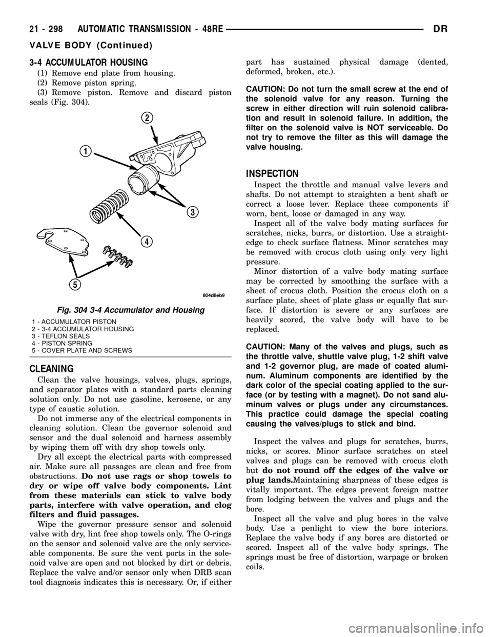
3-4 ACCUMULATOR HOUSING
(1) Remove end plate from housing.
(2) Remove piston spring.
(3) Remove piston. Remove and discard piston
seals (Fig. 304).
CLEANING
Clean the valve housings, valves, plugs, springs,
and separator plates with a standard parts cleaning
solution only. Do not use gasoline, kerosene, or any
type of caustic solution.
Do not immerse any of the electrical components in
cleaning solution. Clean the governor solenoid and
sensor and the dual solenoid and harness assembly
by wiping them off with dry shop towels only.
Dry all except the electrical parts with compressed
air. Make sure all passages are clean and free from
obstructions.Do not use rags or shop towels to
dry or wipe off valve body components. Lint
from these materials can stick to valve body
parts, interfere with valve operation, and clog
filters and fluid passages.
Wipe the governor pressure sensor and solenoid
valve with dry, lint free shop towels only. The O-rings
on the sensor and solenoid valve are the only service-
able components. Be sure the vent ports in the sole-
noid valve are open and not blocked by dirt or debris.
Replace the valve and/or sensor only when DRB scan
tool diagnosis indicates this is necessary. Or, if eitherpart has sustained physical damage (dented,
deformed, broken, etc.).
CAUTION: Do not turn the small screw at the end of
the solenoid valve for any reason. Turning the
screw in either direction will ruin solenoid calibra-
tion and result in solenoid failure. In addition, the
filter on the solenoid valve is NOT serviceable. Do
not try to remove the filter as this will damage the
valve housing.
INSPECTION
Inspect the throttle and manual valve levers and
shafts. Do not attempt to straighten a bent shaft or
correct a loose lever. Replace these components if
worn, bent, loose or damaged in any way.
Inspect all of the valve body mating surfaces for
scratches, nicks, burrs, or distortion. Use a straight-
edge to check surface flatness. Minor scratches may
be removed with crocus cloth using only very light
pressure.
Minor distortion of a valve body mating surface
may be corrected by smoothing the surface with a
sheet of crocus cloth. Position the crocus cloth on a
surface plate, sheet of plate glass or equally flat sur-
face. If distortion is severe or any surfaces are
heavily scored, the valve body will have to be
replaced.
CAUTION: Many of the valves and plugs, such as
the throttle valve, shuttle valve plug, 1-2 shift valve
and 1-2 governor plug, are made of coated alumi-
num. Aluminum components are identified by the
dark color of the special coating applied to the sur-
face (or by testing with a magnet). Do not sand alu-
minum valves or plugs under any circumstances.
This practice could damage the special coating
causing the valves/plugs to stick and bind.
Inspect the valves and plugs for scratches, burrs,
nicks, or scores. Minor surface scratches on steel
valves and plugs can be removed with crocus cloth
butdo not round off the edges of the valve or
plug lands.Maintaining sharpness of these edges is
vitally important. The edges prevent foreign matter
from lodging between the valves and plugs and the
bore.
Inspect all the valve and plug bores in the valve
body. Use a penlight to view the bore interiors.
Replace the valve body if any bores are distorted or
scored. Inspect all of the valve body springs. The
springs must be free of distortion, warpage or broken
coils.
Fig. 304 3-4 Accumulator and Housing
1 - ACCUMULATOR PISTON
2 - 3-4 ACCUMULATOR HOUSING
3 - TEFLON SEALS
4 - PISTON SPRING
5 - COVER PLATE AND SCREWS
21 - 298 AUTOMATIC TRANSMISSION - 48REDR
VALVE BODY (Continued)
Page 2016 of 2627
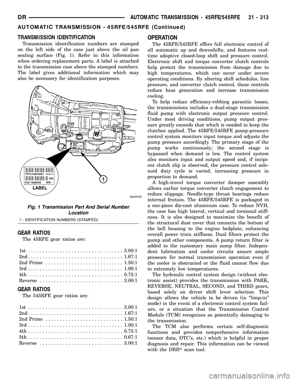
TRANSMISSION IDENTIFICATION
Transmission identification numbers are stamped
on the left side of the case just above the oil pan
sealing surface (Fig. 1). Refer to this information
when ordering replacement parts. A label is attached
to the transmission case above the stamped numbers.
The label gives additional information which may
also be necessary for identification purposes.
GEAR RATIOS
The 45RFE gear ratios are:
1st .................................3.00:1
2nd.................................1.67:1
2nd Prime...........................1.50:1
3rd.................................1.00:1
4th .................................0.75:1
Reverse.............................3.00:1
GEAR RATIOS
The 545RFE gear ratios are:
1st .................................3.00:1
2nd.................................1.67:1
2nd Prime...........................1.50:1
3rd.................................1.00:1
4th .................................0.75:1
5th .................................0.67:1
Reverse.............................3.00:1
OPERATION
The 45RFE/545RFE offers full electronic control of
all automatic up and downshifts, and features real-
time adaptive closed-loop shift and pressure control.
Electronic shift and torque converter clutch controls
help protect the transmission from damage due to
high temperatures, which can occur under severe
operating conditions. By altering shift schedules, line
pressure, and converter clutch control, these controls
reduce heat generation and increase transmission
cooling.
To help reduce efficiency-robbing parasitic losses,
the transmissions includes a dual-stage transmission
fluid pump with electronic output pressure control.
Under most driving conditions, pump output pres-
sure greatly exceeds that which is needed to keep the
clutches applied. The 45RFE/545RFE pump-pressure
control system monitors input torque and adjusts the
pump pressure accordingly. The primary stage of the
pump works continuously; the second stage is
bypassed when demand is low. The control system
also monitors input and output speed and, if incipi-
ent clutch slip is observed, the pressure control sole-
noid duty cycle is varied, increasing pressure in
proportion to demand.
A high-travel torque converter damper assembly
allows earlier torque converter clutch engagement to
reduce slippage. Needle-type thrust bearings reduce
internal friction. The 45RFE/545RFE is packaged in
a one-piece die-cast aluminum case. To reduce NVH,
the case has high lateral, vertical and torsional stiff-
ness. It is also designed to maximize the benefit of
the structural dust cover that connects the bottom of
the bell housing to the engine bedplate, enhancing
overall power train stiffness. Dual filters protect the
pump and other components. A pump return filter is
added to the customary main sump filter. Indepen-
dent lubrication and cooler circuits assure ample
pressure for normal transmission operation even if
the cooler is obstructed or the fluid cannot flow due
to extremely low temperatures.
The hydraulic control system design (without elec-
tronic assist) provides the transmission with PARK,
REVERSE, NEUTRAL, SECOND, and THIRD gears,
based solely on driver shift lever selection. This
design allows the vehicle to be driven (in ªlimp-inº
mode) in the event of a electronic control system fail-
ure, or a situation that the Transmission Control
Module (TCM) recognizes as potentially damaging to
the transmission.
The TCM also performs certain self-diagnostic
functions and provides comprehensive information
(sensor data, DTC's, etc.) which is helpful in proper
diagnosis and repair. This information can be viewed
with the DRBtscan tool.
Fig. 1 Transmission Part And Serial Number
Location
1 - IDENTIFICATION NUMBERS (STAMPED)
DRAUTOMATIC TRANSMISSION - 45RFE/545RFE 21 - 313
AUTOMATIC TRANSMISSION - 45RFE/545RFE (Continued)
Page 2029 of 2627
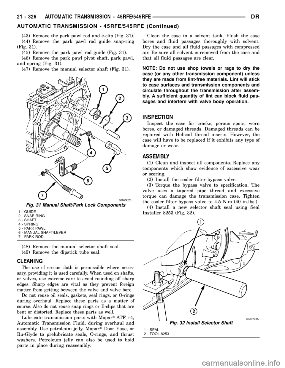
(43) Remove the park pawl rod and e-clip (Fig. 31).
(44) Remove the park pawl rod guide snap-ring
(Fig. 31).
(45) Remove the park pawl rod guide (Fig. 31).
(46) Remove the park pawl pivot shaft, park pawl,
and spring (Fig. 31).
(47) Remove the manual selector shaft (Fig. 31).
(48) Remove the manual selector shaft seal.
(49) Remove the dipstick tube seal.
CLEANING
The use of crocus cloth is permissible where neces-
sary, providing it is used carefully. When used on shafts,
or valves, use extreme care to avoid rounding off sharp
edges. Sharp edges are vital as they prevent foreign
matter from getting between the valve and valve bore.
Do not reuse oil seals, gaskets, seal rings, or O-rings
during overhaul. Replace these parts as a matter of
course. Also do not reuse snap rings or E-clips that are
bent or distorted. Replace these parts as well.
Lubricate transmission parts with MopartATF +4,
Automatic Transmission Fluid, during overhaul and
assembly. Use petroleum jelly, MopartDoor Ease, or
Ru-Glyde to prelubricate seals, O-rings, and thrust
washers. Petroleum jelly can also be used to hold
parts in place during reassembly.Clean the case in a solvent tank. Flush the case
bores and fluid passages thoroughly with solvent.
Dry the case and all fluid passages with compressed
air. Be sure all solvent is removed from the case and
that all fluid passages are clear.
NOTE: Do not use shop towels or rags to dry the
case (or any other transmission component) unless
they are made from lint-free materials. Lint will stick
to case surfaces and transmission components and
circulate throughout the transmission after assem-
bly. A sufficient quantity of lint can block fluid pas-
sages and interfere with valve body operation.
INSPECTION
Inspect the case for cracks, porous spots, worn
bores, or damaged threads. Damaged threads can be
repaired with Helicoil thread inserts. However, the
case will have to be replaced if it exhibits any type of
damage or wear.
ASSEMBLY
(1) Clean and inspect all components. Replace any
components which show evidence of excessive wear
or scoring.
(2) Install the cooler filter bypass valve.
(3) Torque the bypass valve to specification. The
valve uses a tapered pipe thread and excessive
torque can damage the transmission case. Tighten
the cooler filter bypass valve to 4.5 N´m (40 in.lbs.).
(4) Install a new selector shaft seal using Seal
Installer 8253 (Fig. 32).
Fig. 31 Manual Shaft/Park Lock Components
1 - GUIDE
2 - SNAP-RING
3 - SHAFT
4 - SPRING
5 - PARK PAWL
6 - MANUAL SHAFT/LEVER
7 - PARK ROD
Fig. 32 Install Selector Shaft
1 - SEAL
2 - TOOL 8253
21 - 326 AUTOMATIC TRANSMISSION - 45RFE/545RFEDR
AUTOMATIC TRANSMISSION - 45RFE/545RFE (Continued)
Page 2069 of 2627
FLUID AND FILTER
DIAGNOSIS AND TESTING
DIAGNOSIS AND TESTING - EFFECTS OF
INCORRECT FLUID LEVEL
A low fluid level allows the pump to take in air
along with the fluid. Air in the fluid will cause fluid
pressures to be low and develop slower than normal.
If the transmission is overfilled, the gears churn the
fluid into foam. This aerates the fluid and causing
the same conditions occurring with a low level. In
either case, air bubbles cause fluid overheating, oxi-
dation and varnish buildup which interferes with
valve and clutch operation. Foaming also causes fluid
expansion which can result in fluid overflow from the
transmission vent or fill tube. Fluid overflow can eas-
ily be mistaken for a leak if inspection is not careful.
DIAGNOSIS AND TESTING - CAUSES OF
BURNT FLUID
Burnt, discolored fluid is a result of overheating
which has three primary causes.
(1) Internal clutch slippage, usually caused by low
line pressure, inadequate clutch apply pressure, or
clutch seal failure.
(2) A result of restricted fluid flow through the
main and/or auxiliary cooler. This condition is usu-
ally the result of a faulty or improperly installed
drainback valve, a damaged main cooler, or severe
restrictions in the coolers and lines caused by debris
or kinked lines.
(3) Heavy duty operation with a vehicle not prop-
erly equipped for this type of operation. Trailer tow-
ing or similar high load operation will overheat the
transmission fluid if the vehicle is improperly
equipped. Such vehicles should have an auxiliary
transmission fluid cooler, a heavy duty cooling sys-
tem, and the engine/axle ratio combination needed to
handle heavy loads.
DIAGNOSIS AND TESTING - FLUID
CONTAMINATION
Transmission fluid contamination is generally a
result of:
²adding incorrect fluid
²failure to clean dipstick and fill tube when
checking level
²engine coolant entering the fluid
²internal failure that generates debris
²overheat that generates sludge (fluid break-
down)
²failure to replace contaminated converter after
repairThe use of non-recommended fluids can result in
transmission failure. The usual results are erratic
shifts, slippage, abnormal wear and eventual failure
due to fluid breakdown and sludge formation. Avoid
this condition by using recommended fluids only.
The dipstick cap and fill tube should be wiped
clean before checking fluid level. Dirt, grease and
other foreign material on the cap and tube could fall
into the tube if not removed beforehand. Take the
time to wipe the cap and tube clean before withdraw-
ing the dipstick.
Engine coolant in the transmission fluid is gener-
ally caused by a cooler malfunction. The only remedy
is to replace the radiator as the cooler in the radiator
is not a serviceable part. If coolant has circulated
through the transmission, an overhaul is necessary.
The torque converter should also be replaced when-
ever a failure generates sludge and debris. This is
necessary because normal converter flushing proce-
dures will not remove all contaminants.
STANDARD PROCEDURE
STANDARD PROCEDURE - FLUID LEVEL
CHECK
Low fluid level can cause a variety of conditions
because it allows the pump to take in air along with
the fluid. As in any hydraulic system, air bubbles
make the fluid spongy, therefore, pressures will be
low and build up slowly.
Improper filling can also raise the fluid level too
high. When the transmssion has too much fluid, the
geartrain churns up foam and cause the same condi-
tions which occur with a low fluid level.
In either case, air bubbles can cause overheating
and/or fluid oxidation, and varnishing. This can
interfere with normal valve, clutch, and accumulator
operation. Foaming can also result in fluid escaping
from the transmission vent where it may be mis-
taken for a leak.
After the fluid has been checked, seat the dipstick
fully to seal out water and dirt.
The transmission has a dipstick to check oil level.
It is located on the right side of the engine. Be sure
to wipe all dirt from dipstick handle before removing.
The torque converter fills in both the P (PARK)
and N (NEUTRAL) positions. Place the selector lever
in P (PARK) to be sure that the fluid level check is
accurate.The engine should be running at idle
speed for at least one minute, with the vehicle
on level ground.At normal operating temperature
(approximately 82 C. or 180 F.), the fluid level is cor-
rect if it is in the HOT region (cross-hatched area) on
the oil level indicator. The fluid level will be approx-
21 - 366 AUTOMATIC TRANSMISSION - 45RFE/545RFEDR
Page 2096 of 2627
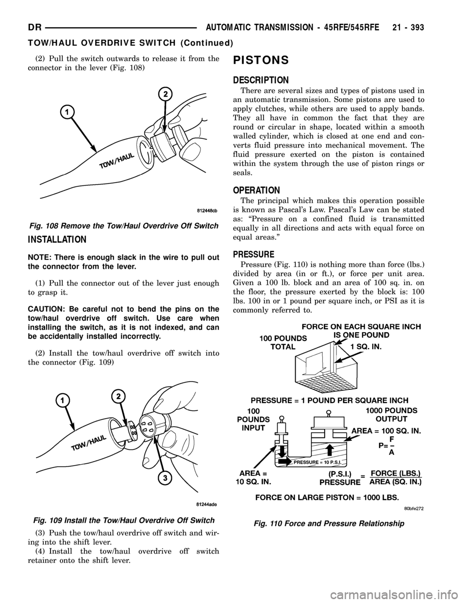
(2) Pull the switch outwards to release it from the
connector in the lever (Fig. 108)
INSTALLATION
NOTE: There is enough slack in the wire to pull out
the connector from the lever.
(1) Pull the connector out of the lever just enough
to grasp it.
CAUTION: Be careful not to bend the pins on the
tow/haul overdrive off switch. Use care when
installing the switch, as it is not indexed, and can
be accidentally installed incorrectly.
(2) Install the tow/haul overdrive off switch into
the connector (Fig. 109)
(3) Push the tow/haul overdrive off switch and wir-
ing into the shift lever.
(4) Install the tow/haul overdrive off switch
retainer onto the shift lever.
PISTONS
DESCRIPTION
There are several sizes and types of pistons used in
an automatic transmission. Some pistons are used to
apply clutches, while others are used to apply bands.
They all have in common the fact that they are
round or circular in shape, located within a smooth
walled cylinder, which is closed at one end and con-
verts fluid pressure into mechanical movement. The
fluid pressure exerted on the piston is contained
within the system through the use of piston rings or
seals.
OPERATION
The principal which makes this operation possible
is known as Pascal's Law. Pascal's Law can be stated
as: ªPressure on a confined fluid is transmitted
equally in all directions and acts with equal force on
equal areas.º
PRESSURE
Pressure (Fig. 110) is nothing more than force (lbs.)
divided by area (in or ft.), or force per unit area.
Given a 100 lb. block and an area of 100 sq. in. on
the floor, the pressure exerted by the block is: 100
lbs. 100 in or 1 pound per square inch, or PSI as it is
commonly referred to.
Fig. 108 Remove the Tow/Haul Overdrive Off Switch
Fig. 109 Install the Tow/Haul Overdrive Off SwitchFig. 110 Force and Pressure Relationship
DRAUTOMATIC TRANSMISSION - 45RFE/545RFE 21 - 393
TOW/HAUL OVERDRIVE SWITCH (Continued)