automatic transmission fluid type DODGE RAM 1500 1998 2.G Owner's Manual
[x] Cancel search | Manufacturer: DODGE, Model Year: 1998, Model line: RAM 1500, Model: DODGE RAM 1500 1998 2.GPages: 2627
Page 2115 of 2627
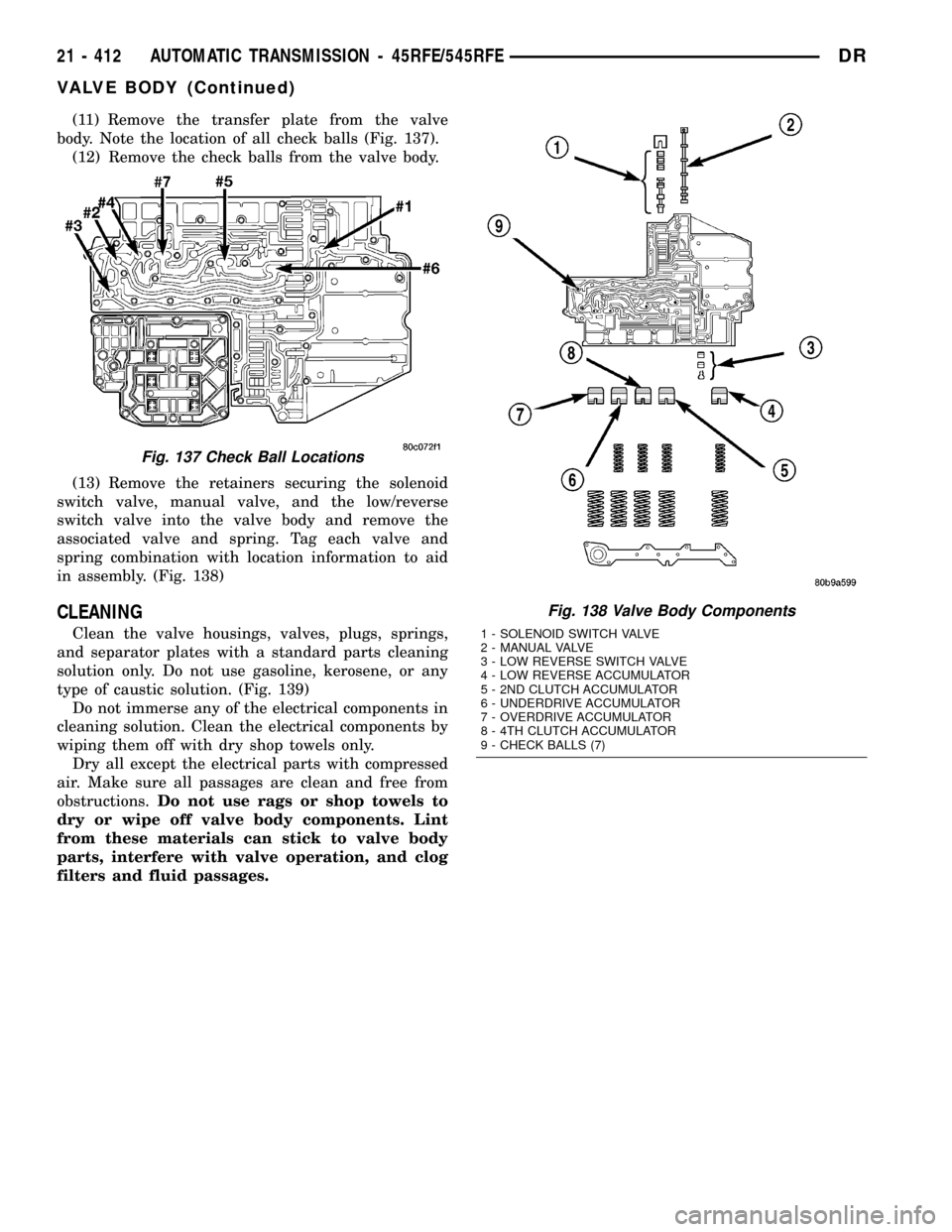
(11) Remove the transfer plate from the valve
body. Note the location of all check balls (Fig. 137).
(12) Remove the check balls from the valve body.
(13) Remove the retainers securing the solenoid
switch valve, manual valve, and the low/reverse
switch valve into the valve body and remove the
associated valve and spring. Tag each valve and
spring combination with location information to aid
in assembly. (Fig. 138)
CLEANING
Clean the valve housings, valves, plugs, springs,
and separator plates with a standard parts cleaning
solution only. Do not use gasoline, kerosene, or any
type of caustic solution. (Fig. 139)
Do not immerse any of the electrical components in
cleaning solution. Clean the electrical components by
wiping them off with dry shop towels only.
Dry all except the electrical parts with compressed
air. Make sure all passages are clean and free from
obstructions.Do not use rags or shop towels to
dry or wipe off valve body components. Lint
from these materials can stick to valve body
parts, interfere with valve operation, and clog
filters and fluid passages.
Fig. 137 Check Ball Locations
Fig. 138 Valve Body Components
1 - SOLENOID SWITCH VALVE
2 - MANUAL VALVE
3 - LOW REVERSE SWITCH VALVE
4 - LOW REVERSE ACCUMULATOR
5 - 2ND CLUTCH ACCUMULATOR
6 - UNDERDRIVE ACCUMULATOR
7 - OVERDRIVE ACCUMULATOR
8 - 4TH CLUTCH ACCUMULATOR
9 - CHECK BALLS (7)
21 - 412 AUTOMATIC TRANSMISSION - 45RFE/545RFEDR
VALVE BODY (Continued)
Page 2186 of 2627
IDENTIFICATION
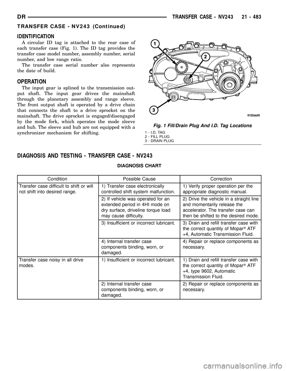
A circular ID tag is attached to the rear case of
each transfer case (Fig. 1). The ID tag provides the
transfer case model number, assembly number, serial
number, and low range ratio.
The transfer case serial number also represents
the date of build.
OPERATION
The input gear is splined to the transmission out-
put shaft. The input gear drives the mainshaft
through the planetary assembly and range sleeve.
The front output shaft is operated by a drive chain
that connects the shaft to a drive sprocket on the
mainshaft. The drive sprocket is engaged/disengaged
by the mode fork, which operates the mode sleeve
and hub. The sleeve and hub are not equipped with a
synchronizer mechanism for shifting.
DIAGNOSIS AND TESTING - TRANSFER CASE - NV243
DIAGNOSIS CHART
Condition Possible Cause Correction
Transfer case difficult to shift or will
not shift into desired range.1) Transfer case electronically
controlled shift system malfunction.1) Verify proper operation per the
appropriate diagnostic manual.
2) If vehicle was operated for an
extended period in 4HI mode on
dry surface, driveline torque load
may cause difficulty.2) Drive the vehicle in a straight line
and momentarily release the
accelerator. The transfer case can
then be shifted to the desired mode.
3) Insufficient or incorrect lubricant. 3) Drain and refill transfer case with
the correct quantity of MoparTAT F
+4, Automatic Transmission Fluid.
4) Internal transfer case
components binding, worn, or
damaged.4) Repair or replace components as
necessary.
Transfer case noisy in all drive
modes.1) Insufficient or incorrect lubricant. 1) Drain and refill transfer case with
the correct quantity of MoparTAT F
+4, type 9602, Automatic
Transmission Fluid.
2) Internal transfer case
components binding, worn, or
damaged.2) Repair or replace components as
necessary.
Fig. 1 Fill/Drain Plug And I.D. Tag Locations
1 - I.D. TAG
2 - FILL PLUG
3 - DRAIN PLUG
DRTRANSFER CASE - NV243 21 - 483
TRANSFER CASE - NV243 (Continued)
Page 2246 of 2627
IDENTIFICATION
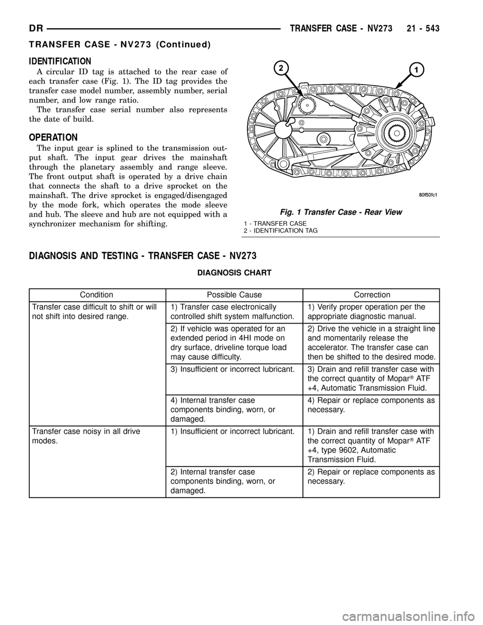
A circular ID tag is attached to the rear case of
each transfer case (Fig. 1). The ID tag provides the
transfer case model number, assembly number, serial
number, and low range ratio.
The transfer case serial number also represents
the date of build.
OPERATION
The input gear is splined to the transmission out-
put shaft. The input gear drives the mainshaft
through the planetary assembly and range sleeve.
The front output shaft is operated by a drive chain
that connects the shaft to a drive sprocket on the
mainshaft. The drive sprocket is engaged/disengaged
by the mode fork, which operates the mode sleeve
and hub. The sleeve and hub are not equipped with a
synchronizer mechanism for shifting.
DIAGNOSIS AND TESTING - TRANSFER CASE - NV273
DIAGNOSIS CHART
Condition Possible Cause Correction
Transfer case difficult to shift or will
not shift into desired range.1) Transfer case electronically
controlled shift system malfunction.1) Verify proper operation per the
appropriate diagnostic manual.
2) If vehicle was operated for an
extended period in 4HI mode on
dry surface, driveline torque load
may cause difficulty.2) Drive the vehicle in a straight line
and momentarily release the
accelerator. The transfer case can
then be shifted to the desired mode.
3) Insufficient or incorrect lubricant. 3) Drain and refill transfer case with
the correct quantity of MoparTAT F
+4, Automatic Transmission Fluid.
4) Internal transfer case
components binding, worn, or
damaged.4) Repair or replace components as
necessary.
Transfer case noisy in all drive
modes.1) Insufficient or incorrect lubricant. 1) Drain and refill transfer case with
the correct quantity of MoparTAT F
+4, type 9602, Automatic
Transmission Fluid.
2) Internal transfer case
components binding, worn, or
damaged.2) Repair or replace components as
necessary.
Fig. 1 Transfer Case - Rear View
1 - TRANSFER CASE
2 - IDENTIFICATION TAG
DRTRANSFER CASE - NV273 21 - 543
TRANSFER CASE - NV273 (Continued)