oil pressure DODGE RAM 1500 1998 2.G User Guide
[x] Cancel search | Manufacturer: DODGE, Model Year: 1998, Model line: RAM 1500, Model: DODGE RAM 1500 1998 2.GPages: 2627
Page 329 of 2627

CONDITION POSSIBLE CAUSES CORRECTION
Temperature gauge reading is
inconsistent (fluctuates, cycles or is
erratic)1. During cold weather operation,
with the heater blower in the high
position, the gauge reading may
drop slightly.1. A normal condition. No correction
necessary.
2. Temperature gauge or engine
mounted gauge sensor defective or
shorted. Also, corroded or loose
wiring in this circuit.2. Check operation of gauge and
repair if necessary. (Refer to 8 -
ELECTRICAL/INSTRUMENT
CLUSTER - DIAGNOSIS AND
TESTING).
3. Gauge reading rises when
vehicle is brought to a stop after
heavy use (engine still running)3. A normal condition. No correction
is necessary. Gauge should return
to normal range after vehicle is
driven.
4. Gauge reading high after
re-starting a warmed up (hot)
engine.4. A normal condition. No correction
is necessary. The gauge should
return to normal range after a few
minutes of engine operation.
5. Coolant level low in radiator (air
will build up in the cooling system
causing the thermostat to open
late).5. Check and correct coolant leaks.
(Refer to 7 - COOLING -
DIAGNOSIS AND TESTING).
6. Cylinder head gasket leaking
allowing exhaust gas to enter
cooling system causing a
thermostat to open late.6. (a) Check for cylinder head
gasket leaks. (Refer to 7 -
COOLING - DIAGNOSIS AND
TESTING).
(b) Check for coolant in the engine
oil. Inspect for white steam emitting
from the exhaust system. Repair as
necessary.
7. Water pump impeller loose on
shaft.7. Check water pump and replace
as necessary. (Refer to 7 -
COOLING/ENGINE/WATER PUMP -
REMOVAL).
8. Loose accessory drive belt.
(water pump slipping)8. (Refer to 7 - COOLING/
ACCESSORY DRIVE/DRIVE BELTS
- DIAGNOSIS AND TESTING).
Check and correct as necessary.
9. Air leak on the suction side of
the water pump allows air to build
up in cooling system causing
thermostat to open late.9. Locate leak and repair as
necessary.
PRESSURE CAP IS BLOWING
OFF STEAM AND/OR COOLANT
TO COOLANT TANK.
TEMPERATURE GAUGE READING
MAY BE ABOVE NORMAL BUT
NOT HIGH. COOLANT LEVEL MAY
BE HIGH IN COOLANT RESERVE/
OVERFLOW TANK1. Pressure relief valve in radiator
cap is defective.1. Check condition of radiator cap
and cap seals. (Refer to 7 -
COOLING/ENGINE/RADIATOR
PRESSURE CAP - DIAGNOSIS
AND TESTING). Replace cap as
necessary.
7 - 14 COOLINGDR
COOLING (Continued)
Page 334 of 2627

STANDARD PROCEDURE - REFILLING
COOLING SYSTEM 5.9L DIESEL ENGINE
Clean cooling system prior to refilling (Refer to 7 -
COOLING - STANDARD PROCEDURE).
(1) Close radiator drain plug.
CAUTION: Due to the use of the one-way check
valve, the engine must not be operating when refill-
ing the cooling system.
NOTE: The diesel engine is equipped with two one-
way check valves (jiggle pins). The check valves
are used as a servicing feature and will vent air
when the system is being filled. Water pressure (or
flow) will hold the valves closed.
(2) Fill the cooling system with a 50/50 mixture of
water and antifreeze.
(3) Fill coolant reserve/overflow tank to the FULL
mark.
(4) Start and operate engine until thermostat
opens. Upper radiator hose should be warm to touch.
(5) If necessary, add 50/50 water and antifreeze
mixture to the coolant reserve/overflow tank to main-
tain coolant level. This level should be between the
ADD and FULL marks. The level in the reserve/over-
flow tank may drop below the ADD mark after three
or four warm-up and cool-down cycles.
STANDARD PROCEDURE - ADDING
ADDITIONAL COOLANT
The use of aluminum cylinder blocks, cylinder
heads and water pumps requires special corrosion
protection. Only MopartAntifreeze/Coolant, 5
Year/100,000 Mile Formula (glycol base coolant with
corrosion inhibitors called HOAT, for Hybrid Organic
Additive Technology) is recommended. This coolant
offers the best engine cooling without corrosion when
mixed with 50% distilled water to obtain a freeze
point of -37ÉC (-35ÉF). If it loses color or becomes con-
taminated, drain, flush, and replace with fresh prop-
erly mixed coolant solution.
CAUTION: Do not use coolant additives that are
claimed to improve engine cooling.
Do not remove the radiator cap to add coolant to
the system. When adding coolant to maintain the cor-
rect level, do so only at the reserve/overflow bottle.
Remove the radiator cap only for testing or when
refilling the system after service. Removing the cap
unnecessarily can cause loss of coolant and allow air
to enter the system, which produces corrosion.
WARNING: DO NOT REMOVE OR LOOSEN THE
RADIATOR CAP WITH THE COOLING SYSTEM HOTAND UNDER PRESSURE. SERIOUS BURNS FROM
THE COOLANT OR HIGH PRESSURE STEAM CAN
OCCUR.
SPECIFICATIONS
TORQUE
DESCRIPTION N´m Ft.
Lbs.In.
Lbs.
Bolt - Automatic Belt
Tensioner to Block41 30 -
Bolt - Automatic Belt
Tensioner Pulley61 45 -
Bolt - Automatic Belt
Tensioner Pulley - Diesel43 32 -
Bolt - Block Heater 2 - 17
Bolts - Generator/
Compressor Mounting
Bracket
# 1 and 2 54 40 -
# 3 40 30 -
Bolts - Generator/
Compressor Mounting
Bracket - Diesel24 18 -
Bolts - Fan Shroud to
Radiator Mounting - All
Except 5.9L Diesel6-55
5.9L Diesel 11.8 - 105
Bolts - Radiator to Support 8.5 - 75
Bolts - Fan Blade to
Viscous Fan Drive24 18 -
Fan Drive - All Except
8.0L/5.9L Diesel50 37 -
8.0L/5.9L Diesel 115 85 -
Bolt - Idler Pulley 54 40 -
Bolt - Idler Pulley - Diesel 43 32 -
Bolts - Thermostat Housing
- All Except 5.9L13 - 112
Bolts - Thermostat Housing
5.9L23 16 -
Bolts - Thermostat Housing
- Diesel10 - 89
Bolts - Power Steering Oil
Cooler8.4 - 75
Bolts - Transmission
Auxiliary Oil Cooler6-55
DRCOOLING 7 - 19
COOLING (Continued)
Page 335 of 2627
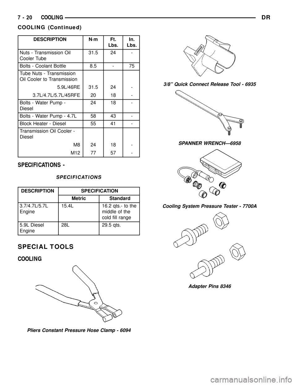
DESCRIPTION N´m Ft.
Lbs.In.
Lbs.
Nuts - Transmission Oil
Cooler Tube31.5 24 -
Bolts - Coolant Bottle 8.5 - 75
Tube Nuts - Transmission
Oil Cooler to Transmission
5.9L/46RE 31.5 24 -
3.7L/4.7L/5.7L/45RFE 20 18 -
Bolts - Water Pump -
Diesel24 18 -
Bolts - Water Pump - 4.7L 58 43 -
Block Heater - Diesel 55 41 -
Transmission Oil Cooler -
Diesel
M8 24 18 -
M12 77 57 -
SPECIFICATIONS -
SPECIFICATIONS
DESCRIPTION SPECIFICATION
Metric Standard
3.7/4.7L/5.7L
Engine15.4L 16.2 qts.- to the
middle of the
cold fill range
5.9L Diesel
Engine28L 29.5 qts.
SPECIAL TOOLS
COOLING
Pliers Constant Pressure Hose Clamp - 6094
3/8º Quick Connect Release Tool - 6935
SPANNER WRENCHÐ6958
Cooling System Pressure Tester - 7700A
Adapter Pins 8346
7 - 20 COOLINGDR
COOLING (Continued)
Page 338 of 2627

INSTALLATION
(1) Install tensioner on to the mounting bracket.
Tighten bolt to 41 N´m (30 ft. lbs.).
(2) Install tensioner and bracket assembly
(3) Install accessory drive belt (Refer to 7 - COOL-
ING/ACCESSORY DRIVE/DRIVE BELTS - INSTAL-
LATION).
BELT TENSIONER - 5.9L
DIESEL
DESCRIPTION
Drive belts on all engines are equipped with a
spring loaded automatic belt tensioner (Fig. 4). This
tensioner maintains constant belt tension at all times
and requires no maintenance or adjustment.
CAUTION: Do not attempt to check belt tension with
a belt tension gauge on vehicles equipped with an
automatic belt tensioner.
OPERATION
WARNING: THE AUTOMATIC BELT TENSIONER
ASSEMBLY IS SPRING LOADED. DO NOT ATTEMPT
TO DISASSEMBLE THE TENSIONER ASSEMBLY.
The automatic belt tensioner maintains correct belt
tension using a coiled spring within the tensioner
housing. The spring applies pressure to the tensioner
arm pressing the arm into the belt, tensioning the
belt.
REMOVAL
WARNING: BECAUSE OF HIGH SPRING PRES-
SURE, DO NOT ATTEMPT TO DISASSEMBLE AUTO-
MATIC TENSIONER. UNIT IS SERVICED AS AN
ASSEMBLY.
(1) Remove accessory drive belt (Refer to 7 -
COOLING/ACCESSORY DRIVE/DRIVE BELTS -
REMOVAL).
(2) Remove tensioner mounting bolt (Fig. 5) and
remove tensioner.
Fig. 4 Accessory Drive Belt - 5.9L Diesel
1 - GENERATOR
2 - WATER PUMP
3 - IDLER
4 - POWER STEERING PUMP
5 - RADIATOR FAN PULLEY
6 - CRANKSHAFT
7 - AUTOMATIC TENSIONER
8 - A/C COMPRESSOR
Fig. 5 AUTOMATIC BELT TENSIONER 5.9L DIESEL
ENGINE
1 - GENERATOR
2 - WATER PUMP
3 - IDLER
4 - POWER STEERING PUMP
5 - RADIATOR FAN PULLEY
6 - CRANKSHAFT
7 - AUTOMATIC TENSIONER
8 - A/C COMPRESSOR
DRACCESSORY DRIVE 7 - 23
BELT TENSIONER-5.7L (Continued)
Page 348 of 2627

OPERATION
Coolant flows through the engine block absorbing
the heat from the engine, then flows to the radiator
where the cooling fins in the radiator transfers the
heat from the coolant to the atmosphere. During cold
weather the ethylene-glycol or propylene-glycol cool-
ant prevents water present in the cooling system
from freezing within temperatures indicated by mix-
ture ratio of coolant to water.
COOLANT RECOVERY
CONTAINER- GAS ENGINES
DESCRIPTION
The coolant reserve/overflow tank is mounted on
top of the fan shroud, and is made of high tempera-
ture plastic (Fig. 1).
OPERATION
The coolant reserve/overflow system works in con-
junction with the radiator pressure cap. It utilizes
thermal expansion and contraction of coolant to keep
coolant free of trapped air. It provides a volume for
expansion and contraction of coolant. It also provides
a convenient and safe method for checking coolant
level and adjusting level at atmospheric pressure.
This is done without removing the radiator pressure
cap. The system also provides some reserve coolantto the radiator to cover minor leaks and evaporation
or boiling losses.
As the engine cools, a vacuum is formed in the
cooling system of both the radiator and engine. Cool-
ant will then be drawn from the coolant tank and
returned to a proper level in the radiator.
REMOVAL
(1) Remove recovery hose from radiator.
(2) Remove the coolant container to fan shroud
mounting bolt.
(3) Tilt the container backward towards the engine
to disengage the mounting pin locking features and
lift the container away from the fan shroud (Fig. 1).
INSTALLATION
(1) Align the coolant container mounting pins into
the slots on the fan shroud and push the container
onto the fan shroud.
(2) Secure the container to the fan shroud with the
bolt. Tighten to 8.5N´m (75 in-lbs).
NOTE: Ensure that the locking feature on the
mounting pins has engaged.
(3) Connect the recovery hose to the radiator (Fig.
1).
RADIATOR FAN - GAS
ENGINES
REMOVAL
CAUTION: If the viscous fan drive is replaced
because of mechanical damage, the cooling fan
blades should also be inspected. Inspect for fatigue
cracks, loose blades, or loose rivets that could
have resulted from excessive vibration. Replace fan
blade assembly if any of these conditions are
found. Also inspect water pump bearing and shaft
assembly for any related damage due to a viscous
fan drive malfunction.
(1) Disconnect negative battery cable from battery.
(2) Remove coolant reserve/overflow container from
fan shroud and lay aside.Do Notdisconnect the
hoses or drain coolant from the container.
(3) The thermal viscous fan drive/fan blade assem-
bly is attached (threaded) to the water pump hub
shaft (Fig. 3). Remove the fan blade/viscous fan drive
assembly from the water pump by turning the
mounting nut counterclockwise as viewed from the
front. Threads on the viscous fan drive areRIGHT-
HAND.A 36 MM Fan Wrench should be used to pre-
vent pulley from rotating (Fig. 2).
Fig. 1 Coolant Recovery Bottle - Gas Engine
1 - SCREW
2 - COOLANT RECOVERY CONTAINER
3 - RADIATOR/RADIATOR CAP
4 - FAN SHROUD
DRENGINE 7 - 33
COOLANT (Continued)
Page 369 of 2627

RADIATOR-3.7L/4.7L/5.7L
DESCRIPTION
The radiator is a aluminum cross-flow design with
horizontal tubes through the radiator core and verti-
cal plastic side tanks (Fig. 38).
This radiator does not contain an internal trans-
mission oil cooler.
OPERATION
The radiator supplies sufficient heat transfer using
the cooling fins interlaced between the horizontal
tubes in the radiator core to cool the engine.
DIAGNOSIS AND TESTING - RADIATOR
COOLANT FLOW
Use the following procedure to determine if coolant
is flowing through the cooling system.
(1) Idle engine until operating temperature is
reached. If the upper radiator hose is warm to the
touch, the thermostat is opening and coolant is flow-
ing to the radiator.
WARNING: HOT, PRESSURIZED COOLANT CAN
CAUSE INJURY BY SCALDING. USING A RAG TO
COVER THE RADIATOR PRESSURE CAP, OPEN
RADIATOR CAP SLOWLY TO THE FIRST STOP. THIS
WILL ALLOW ANY BUILT-UP PRESSURE TO VENT
TO THE RESERVE/OVERFLOW TANK. AFTER PRES-
SURE BUILD-UP HAS BEEN RELEASED, REMOVE
CAP FROM FILLER NECK.
(2) Drain a small amount of coolant from the radi-
ator until the ends of the radiator tubes are visible
through the filler neck. Idle the engine at normal
operating temperature. If coolant is flowing past the
exposed tubes, the coolant is circulating.
REMOVAL
(1) Disconnect battery negative cables.
WARNING: DO NOT REMOVE THE CYLINDER
BLOCK DRAIN PLUGS OR LOOSEN THE RADIATOR
DRAINCOCK WITH THE SYSTEM HOT AND UNDER
PRESSURE. SERIOUS BURNS FROM THE COOL-
ANT CAN OCCUR.
(2) Drain the cooling system (Refer to 7 - COOL-
ING - STANDARD PROCEDURE).
WARNING: CONSTANT TENSION HOSE CLAMPS
ARE USED ON MOST COOLING SYSTEM HOSES.
WHEN REMOVING OR INSTALLING, USE ONLY
TOOLS DESIGNED FOR SERVICING THIS TYPE OF
CLAMP. ALWAYS WEAR SAFETY GLASSES WHEN
SERVICING CONSTANT TENSION CLAMPS.CAUTION: A number or letter is stamped into the
tongue of constant tension clamps. If replacement
is necessary, use only an original equipment clamp
with a matching number or letter and the correct
width.
(3) Remove the hose clamps and hoses from radia-
tor.
(4) Remove the coolant reserve/overflow tank hose
from the radiator filler neck.
(5) Remove the coolant reserve/overflow tank from
the fan shroud (pull straight up). The tank slips into
slots on the fan shroud.
(6) Unclip the power steering hoses from the fan
shroud.
(7) Disconnect the electrical connectors at the
windshield washer reservoir tank and remove the
tank.
(8) Remove the fan shroud mounting bolts and pull
up and out of the radiator tank clips (Fig. 36). Posi-
tion shroud rearward over the fan blades towards
engine.
(9) Disconnect the transmission cooler lines from
the transmission cooler, then plug the transmission
lines and cooler to prevent leakage.
(10) Disconnect the power steering lines from the
power steering cooler, then plug the power steering
lines and cooler to prevent leakage.
Fig. 36 Fan Shroud - Gas Engine
1 - RADIATOR
2 - SCREWS
3 - FAN SHROUD
4 - SLIDE MOUNT
7 - 54 ENGINEDR
Page 371 of 2627

RADIATOR - 5.9L DIESEL
DESCRIPTION
The radiator is a aluminum cross-flow design with
horizontal tubes through the radiator core and verti-
cal plastic side tanks (Fig. 38).
This radiator does not contain an internal trans-
mission oil cooler.
OPERATION
The radiator supplies sufficient heat transfer using
the cooling fins interlaced between the horizontal
tubes in the radiator core to cool the engine.
DIAGNOSIS AND TESTING - RADIATOR
COOLANT FLOW
Use the following procedure to determine if coolant
is flowing through the cooling system.
(1) Idle engine until operating temperature is
reached. If the upper radiator hose is warm to the
touch, the thermostat is opening and coolant is flow-
ing to the radiator.
WARNING: HOT, PRESSURIZED COOLANT CAN
CAUSE INJURY BY SCALDING. USING A RAG TO
COVER THE RADIATOR PRESSURE CAP, OPEN
RADIATOR CAP SLOWLY TO THE FIRST STOP. THIS
WILL ALLOW ANY BUILT-UP PRESSURE TO VENT
TO THE RESERVE/OVERFLOW TANK. AFTER PRES-
SURE BUILD-UP HAS BEEN RELEASED, REMOVE
CAP FROM FILLER NECK.
(2) Drain a small amount of coolant from the radi-
ator until the ends of the radiator tubes are visible
through the filler neck. Idle the engine at normal
operating temperature. If coolant is flowing past the
exposed tubes, the coolant is circulating.
REMOVAL
(1) Disconnect both battery negative cables.
WARNING: DO NOT REMOVE THE CYLINDER
BLOCK DRAIN PLUGS OR LOOSEN THE RADIATOR
DRAINCOCK WITH THE SYSTEM HOT AND UNDER
PRESSURE. SERIOUS BURNS FROM COOLANT
CAN OCCUR.
(2) Drain the cooling system (Refer to 7 - COOL-
ING - STANDARD PROCEDURE).
WARNING: CONSTANT TENSION HOSE CLAMPS
ARE USED ON MOST COOLING SYSTEM HOSES.
WHEN REMOVING OR INSTALLING, USE ONLY
TOOLS DESIGNED FOR SERVICING THIS TYPE OF
CLAMP, SUCH AS SPECIAL CLAMP TOOL (NUMBER6094). ALWAYS WEAR SAFETY GLASSES WHEN
SERVICING CONSTANT TENSION CLAMPS.
CAUTION: A number or letter is stamped into the
tongue of constant tension clamps. If replacement
is necessary, use only an original equipment clamp
with a matching number or letter.
(3) Remove air box and turbocharger inlet tube.
(4) Remove coolant tank hose, washer bottle hose
and the positive battery cable from the fastening
clips located on top of the radiator.
(5) Remove hose clamps and hoses from radiator.
(6) Remove the power steering cooler mounting
bolts and position the power steering cooler out of
the way.
(7) Disconnect the transmission cooler lines at the
transmission cooler. The transmission cooler will
remain on the radiator and can be removed as an
assembly.
(8) Disconnect the electronic viscous fan drive elec-
trical connector.
(9) Using a fastener removal tool, remove the two
push pins and the lower shroud assembly and elec-
tronic viscous fan drive wiring from the upper shroud
assembly. Position wiring out of the way. Do not
impact or damage the electronic viscous fan drive or
pull it's wiring.
(10) Using a fastener tool, remove the wiring har-
ness bracket from the upper fan shroud.
(11) Remove the two radiator upper mounting
bolts (Fig. 38).
(12) Lift radiator straight up and out of engine
compartment. The bottom of the radiator is equipped
with two alignment dowels that fit into holes in the
lower radiator support panel. Rubber biscuits (insu-
lators) are installed to these dowels. Take care not to
damage cooling fins or tubes on the radiator and air
conditioning condenser or the electronic viscous fan
connector when removing.
CLEANING
Clean radiator fins are necessary for good heat
transfer. The radiator and oil cooler fins should be
cleaned when an accumulation of debris has
occurred. With the engine cold, apply cold water and
compressed air to the back (engine side) of the radi-
ator to flush the radiator and/or oil coolers of debris.
INSPECTION
Inspect the radiator side tanks for cracks, and bro-
ken or missing fittings. Inspect the joint where the
tanks seam up to the radiator core for signs of leak-
age and/or deteriorating seals.
Inspect radiator core for corroded, bent or missing
cooling fins. Inspect the core for bent or damaged
cooling tubes.
7 - 56 ENGINEDR
Page 372 of 2627

INSTALLATION
(1) Install rubber insulators to alignment dowels
at lower part of radiator.
(2) Lower the radiator into position while guiding
the two alignment dowels into lower radiator sup-
port. Different alignment holes are provided in the
lower radiator support for each engine application.
(3) Install two upper radiator mounting bolts.
Tighten bolts to 11.8 N´m (105 in. lbs.) torque.
(4) Connect both radiator hoses and install hose
clamps.
(5) Connect transmission cooler lines to transmis-
sion cooler. Inspect quick connect fittings for debris
and install until an audible ªclickº is heard. Pull
apart to verify connection.
(6) Position power steering cooler on the radiator
and tighten nuts to 10 N´m (90 in. lbs.)
(7) Position the electronic viscous fan wiring in the
channel in the upper shroud (Fig. 39). Make sure
that the grommet seats into the channel.
(8) Install lower radiator shroud using two push
pins. Make sure the wiring viscous fan drive wiring
is not pinched.
(9) Install the wiring harness bracket to the upper
shroud.
(10) Connect the viscous fan drive wiring to the
wiring harness.(11) Install the coolant recovery container (Refer to
7 - COOLING/ENGINE/COOLANT RECOVERY
CONTAINER - INSTALLATION).
(12) Position coolant recovery tank hose, washer
bottle hose and the positive battery cable into the
clips located on the top of the radiator.
(13) Install air box and turbocharger inlet hose.
Tighten clamps to 4 N´m (35 in. lbs.).
(14) Position heater controls tofull heatposition.
(15) Fill cooling system with coolant (Refer to 7 -
COOLING - STANDARD PROCEDURE).
(16) Operate engine until it reaches normal tem-
perature. Check cooling system and automatic trans-
mission (if equipped) fluid levels.
RADIATOR PRESSURE CAP
DESCRIPTION
All cooling systems are equipped with a pressure
cap (Fig. 40). For 5.9L engines, the pressure cap is
located on top of the radiator outlet tank. For all
engines, the pressure cap is located on top of the
coolant degas container. The cap releases pressure at
some point within a range of 97-to-124 kPa (14-to-18
psi). The pressure relief point (in pounds) is engraved
on top of the cap
The cooling system will operate at pressures
slightly above atmospheric pressure. This results in a
higher coolant boiling point allowing increased radi-
ator cooling capacity. The cap contains a spring-
Fig. 38 Fan Shroud Mounting - 5.9L Diesel Engine
1 - RADIATOR SUPPORT
2 - UPPER FAN SHROUD
3 - BOLTS (2)
4 - LOWER FAN SHROUD
5 - RADIATOR
Fig. 39 Electronically Controlled Viscous Fan Drive
Wiring
1 - UPPER SHROUD
2 - WIRING
DRENGINE 7 - 57
RADIATOR - 5.9L DIESEL (Continued)
Page 403 of 2627

Engine Control Module (ECM) over the PCI data bus
to illuminate the check gauges indicator for a coolant
temperature high condition.
²Fasten Seat Belt Warning- The instrument
cluster chime tone generator will generate repetitive
chimes at a slow rate each time the ignition switch is
turned to the On or Start positions to announce that
the hard wired inputs from the seat belt switch and
the ignition switch indicate that the driver side front
seat belt is not fastened. The chimes will continue to
sound for a duration of about six seconds, until the
driver side front seat belt is fastened, or until the
ignition switch is turned to the Off position, which-
ever occurs first.
²Head/Park Lamps-On Warning- The instru-
ment cluster chime tone generator will generate
repetitive chimes at a slow rate to announce that the
hard wired inputs from the driver door ajar switch,
the ignition switch, and the exterior lighting circuitry
of the headlamp switch indicate that the exterior
lamps are turned On with the driver door opened
and the ignition switch in the Off position. The
chimes will continue to sound until the exterior
lamps are turned Off, the driver door is closed, or the
ignition switch is turned to the On position, or the
battery protection time-out expires, whichever occurs
first.
²Key-In-Ignition Warning- The instrument
cluster chime tone generator will generate repetitive
chimes at a slow rate to announce that the hard
wired inputs from the driver door ajar switch, the
ignition switch, and the key-in ignition circuitry of
the ignition switch indicate that the key is in the
ignition lock cylinder with the driver door opened
and the ignition switch in the Off position. The
chimes will continue to sound until the key is
removed from the ignition lock cylinder, the driver
door is closed, or the ignition switch is turned to the
On position, whichever occurs first.
²Low Fuel Warning- The instrument cluster
chime tone generator will generate one chime tone
when the low fuel indicator is illuminated by the
instrument cluster. The instrument cluster uses a
percent tank full message input received from the
PCM over the PCI data bus indicating that there is
less than about one-eighth tank of fuel remaining to
illuminate the low fuel indicator. This chime feature
will only occur once in an ignition cycle.
²Low Oil Pressure Warning (Diesel Engine
Only)- The instrument cluster chime tone generator
will generate repetitive chimes at a fast rate when
the check gauges indicator is illuminated for a low oil
pressure condition. The instrument cluster uses
engine speed and oil pressure message inputs
received from the diesel Engine Control Module
(ECM) over the PCI data bus indicating that theengine is running and that the oil pressure is low to
illuminate the check gauges indicator. The chimes
will continue to sound for five seconds, until the
engine oil pressure message indicates that the oil
pressure is not low, or until the engine speed mes-
sage indicates that the engine is not running, which-
ever occurs first. This chime tone will only occur once
in an ignition cycle.
²Low Wash Warning- The instrument cluster
chime tone generator will generate one chime tone
when the low washer fluid indicator is illuminated by
the instrument cluster. The instrument cluster uses a
message input received from the Front Control Mod-
ule (FCM) over the PCI data bus indicating that
washer fluid level is low within the washer reservoir.
This chime feature will only occur once in an ignition
cycle.
²Overspeed Warning- The instrument cluster
chime tone generator will generate one chime tone to
announce that a vehicle speed message input
received from the PCM over the PCI data bus indi-
cates that the vehicle speed is above a pre-programed
limit.
²Park Brake Reminder- The instrument clus-
ter chime tone generator will generate ten repetitive
chimes at a slow rate to announce that the hard
wired input from the park brake switch and a vehicle
speed message input received from the PCM over the
PCI data bus indicates that the park brake is applied
and the vehicle is moving. This chime feature will
repeat each time the input conditions are met.
²Sentry Key Immobilizer System ªCustomer
Learnº Mode Announcement- This chime feature
is only active on vehicles equipped with the optional
Sentry Key Immobilizer System (SKIS) and sold in
markets where the optional ªCustomer Learnº pro-
gramming feature is available. The instrument clus-
ter chime tone generator will generate one chime to
announce that a status message input received from
the Sentry Key Immobilizer Module (SKIM) over the
PCI data bus indicates that the SKIS is in the ªCus-
tomer Learnº mode, which is used for programming
additional sentry key transponders.
²Transmission Temperature High Warning
(Automatic Transmission only)- The instrument
cluster chime tone generator will generate repetitive
chimes at a slow rate when the transmission temper-
ature indicator is illuminated for a high or critical
transmission fluid temperature condition. The instru-
ment cluster uses transmission temperature message
inputs received from the Transmission Control Mod-
ule (TCM) over the PCI data bus to illuminate the
indicator for a transmission temperature high condi-
tion.
²Turn Signal On Warning- The instrument
cluster chime tone generator will generate repetitive
8B - 2 CHIME/BUZZERDR
CHIME WARNING SYSTEM (Continued)
Page 411 of 2627

NOTE: ECM Inputs:
²Accelerator Pedal Position Sensor (APPS) Volts
²APPS1 Signal Ð For off engine APPS
²APPS2 Signal Ð For off engine APPS
²APPS idle validation switches #1 and #2
²Battery Temperature
²Battery voltage
²Camshaft Position Sensor (CMP)
²CCD bus (+) circuits
²CCD bus (-) circuits
²Crankshaft Position Sensor (CKP)
²Data link connection for DRB scan tool
²Engine Coolant Temperature (ECT) sensor
²Fuel pressure sensor
²Fan speed (engine cooling fan)
²Ground circuits
²Inlet air temperature sensor/pressure sensor
²Intake air temperature sensor/MAP sensor
²Oil Pressure switch
²Power ground
²Sensor return
²Signal ground
²Water-In-Fuel (WIF) sensor
NOTE: ECM Outputs:
After inputs are received by the ECM, certain sen-
sors, switches and components are controlled or reg-
ulated by the ECM. These are consideredECM
Outputs.These outputs are for:
²CCD bus (+) circuits
²CCD bus (-) circuits
²CKP and APPS outputs to the PCM
²Data link connection for DRB scan tool
²Fan Clutch PWM
²Five volt sensor supply
²Fuel Control Actuator
²Fuel transfer (lift) pump
²Intake manifold air heater relays #1 and #2 con-
trol circuits
²Malfunction indicator lamp (Check engine lamp)
(databus)
²Oil Pressure Swith/warning lamp (databus)
²Wait-to-start warning lamp (databus)
²Water-In-Fuel (WIF) warning lamp (databus)
REMOVAL
The engine control module (ECM) is bolted to a
support bracket near the fuel filter. The support
bracket mounts to the block with four capscrews and
vibration isolators. A ground wire is fastened to the
bracket. The other end of the wire is fastened to the
engine block.
(1) Record any Diagnostic Trouble Codes (DTC's)
found in the ECM.To avoid possible voltage spike damage to the
ECM, ignition key must be off, and both negative
battery cables must be disconnected before unplug-
ging ECM connectors.
(2) Disconnect both negative battery cables at both
batteries.
(3) Remove the 50±way and 60±way connector
bolts at the ECM. Note: The connector bolt is a
female allen head. As bolt is being removed, very
carefully remove connectors from the ECM.
(4) Remove five ECM mounting bolts and remove
ECM from the vehicle (Fig. 2).
INSTALLATION
Do not apply paint to ECM or a poor ground will
result.
(1) Position the ECM to the ECM support bracket
and install the five mounting bolts. Tighten the bolts
to 24 N´m (18 ft. lbs.).
(2) Check pin connectors in ECM, 50±way and
60±way connectors for corrosion or damage. Repair
as necessary.
(3) Clean pins in the 50±way and 60±way electri-
cal connectors with a electrical contact cleaner.
(4) Install the 50±way and 60±way connectors to
ECM. Tighten connector bolts to 3 N´m (27 in. lbs.).
(5) Reconnect both negative battery cables.
(6) Use DRBIIItscan tool to erase any stored com-
panion DTC's from ECM.
Fig. 2 Diesel ECM
1 - ENGINE CONTROL MODULE (ECM)
2 - ECM MOUNTING BOLT
3 - 50-WAY CONNECTOR
4 - SUPPORT PLATE
5 - 60-WAY CONNECTOR
8E - 4 ELECTRONIC CONTROL MODULESDR
ENGINE CONTROL MODULE (Continued)