speaker DODGE RAM 1500 1998 2.G User Guide
[x] Cancel search | Manufacturer: DODGE, Model Year: 1998, Model line: RAM 1500, Model: DODGE RAM 1500 1998 2.GPages: 2627
Page 1052 of 2627
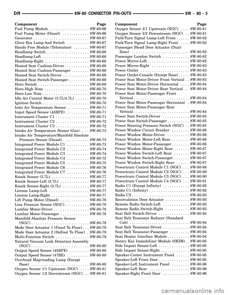
Component Page
Fuel Pump Module.................. 8W-80-66
Fuel Pump Motor (Diesel)............ 8W-80-66
Generator......................... 8W-80-67
Glove Box Lamp And Switch.......... 8W-80-67
Hands Free Module (Telematics)....... 8W-80-67
Headlamp Switch................... 8W-80-68
Headlamp-Left..................... 8W-80-68
Headlamp-Right.................... 8W-80-68
Heated Seat Cushion-Driver........... 8W-80-68
Heated Seat Cushion-Passenger........ 8W-80-69
Heated Seat Switch-Driver............ 8W-80-69
Heated Seat Switch-Passenger......... 8W-80-69
Horn Switch....................... 8W-80-69
Horn-High Note.................... 8W-80-70
Horn-Low Note..................... 8W-80-70
Idle Air Control Motor (3.7L/4.7L)...... 8W-80-70
Ignition Switch..................... 8W-80-70
Inlet Air Temperature Sensor.......... 8W-80-71
Input Speed Sensor (45RFE).......... 8W-80-71
Instrument Cluster C1............... 8W-80-71
Instrument Cluster C2............... 8W-80-72
Instrument Cluster C3............... 8W-80-72
Intake Air Temperature Sensor (Gas).... 8W-80-73
Intake Air Temperature/Manifold Absolute
Pressure Sensor (Diesel)............ 8W-80-73
Integrated Power Module C1.......... 8W-80-73
Integrated Power Module C2.......... 8W-80-74
Integrated Power Module C3.......... 8W-80-74
Integrated Power Module C4.......... 8W-80-75
Integrated Power Module C5.......... 8W-80-75
Integrated Power Module C6.......... 8W-80-76
Integrated Power Module C7.......... 8W-80-76
Knock Sensor (3.7L)................. 8W-80-77
Knock Sensor-Left (5.7L)............. 8W-80-77
Knock Sensor-Right (5.7L)............ 8W-80-77
License Lamp-Left.................. 8W-80-77
License Lamp-Right................. 8W-80-77
Lift Pump Motor (Diesel)............. 8W-80-78
Line Pressure Sensor (NGC)........... 8W-80-78
Lumbar Motor-Driver................ 8W-80-78
Lumbar Motor-Passenger............. 8W-80-78
Manifold Absolute Pressure Sensor
(NGC).......................... 8W-80-79
Mode Door Actuator 1 (Panel To Floor) . . . 8W-80-79
Mode Door Actuator 2 (Defrost To Floor) . 8W-80-79
Multi-Function Switch............... 8W-80-79
Natural Vacuum Leak Detection Assembly
(NGC).......................... 8W-80-80
Output Speed Sensor (45RFE)......... 8W-80-80
Output Speed Sensor (47RE).......... 8W-80-80
Overhead Map/reading Lamp (Except
Base).......................... 8W-80-80
Oxygen Sensor 1/1 Upstream (NGC).... 8W-80-81
Oxygen Sensor 1/2 Downstream (NGC) . . 8W-80-81Component Page
Oxygen Sensor 2/1 Upstream (NGC).... 8W-80-81
Oxygen Sensor 2/2 Downstream (NGC) . . 8W-80-81
Park/Turn Signal Lamp-Left Front...... 8W-80-82
Park/Turn Signal Lamp-Right Front.... 8W-80-82
Passenger Blend Door Actuator (Dual-
Zone).......................... 8W-80-82
Passenger Lumbar Switch............ 8W-80-82
Power Mirror-Left................... 8W-80-82
Power Mirror-Right................. 8W-80-83
Power Outlet...................... 8W-80-83
Power Outlet-Console (Except Base)..... 8W-80-83
Power Seat Motor-Driver Front Vertical . . 8W-80-83
Power Seat Motor-Driver Horizontal.... 8W-80-84
Power Seat Motor-Driver Rear Vertical . . 8W-80-84
Power Seat Motor-Passenger Front
Vertical......................... 8W-80-84
Power Seat Motor-Passenger Horizontal . 8W-80-84
Power Seat Motor-Passenger Rear
Vertical......................... 8W-80-84
Power Seat Switch-Driver............ 8W-80-85
Power Seat Switch-Passenger.......... 8W-80-85
Power Steering Pressure Switch (NGC) . . 8W-80-85
Power Window Circuit Breaker........ 8W-80-86
Power Window Motor-Driver.......... 8W-80-86
Power Window Motor-Left Rear........ 8W-80-86
Power Window Motor-Passenger........ 8W-80-86
Power Window Motor-Right Rear....... 8W-80-87
Power Window Switch-Left Rear....... 8W-80-87
Power Window Switch-Passenger....... 8W-80-87
Power Window Switch-Right Rear...... 8W-80-87
Powertrain Control Module C1 (NGC) . . . 8W-80-88
Powertrain Control Module C2 (NGC) . . . 8W-80-89
Powertrain Control Module C3 (NGC) . . . 8W-80-90
Powertrain Control Module C4 (NGC) . . . 8W-80-91
Radio C1 (Except Infinity)............ 8W-80-92
Radio C1 (Infinity).................. 8W-80-92
Radio C2.......................... 8W-80-93
Recirculation Door Actuator........... 8W-80-93
Remote Radio Switch-Left............ 8W-80-93
Remote Radio Switch-Right........... 8W-80-93
Seat Belt Switch-Driver.............. 8W-80-94
Seat Belt Tensioner Reducer (Standard
Cab)........................... 8W-80-94
Seat Belt Tensioner-Driver............ 8W-80-94
Seat Belt Tensioner-Passenger......... 8W-80-94
Seat Heater Interface Module.......... 8W-80-94
Sentry Key Immobilizer Module (SKIM) . . 8W-80-95
Side Impact Sensor-Left.............. 8W-80-95
Side Impact Sensor-Right............. 8W-80-95
Speaker-Center Instrument Panel...... 8W-80-95
Speaker-Left Front Door.............. 8W-80-95
Speaker-Left Instrument Panel........ 8W-80-96
Speaker-Left Rear.................. 8W-80-96
Speaker-Right Front Door............ 8W-80-96
DR8W-80 CONNECTOR PIN-OUTS 8W - 80 - 3
Page 1053 of 2627

Component Page
Speaker-Right Instrument Panel....... 8W-80-96
Speaker-Right Rear................. 8W-80-96
Speed Control Servo (Diesel A/T/NGC) . . . 8W-80-97
Speed Control Switch-Left (ETC)....... 8W-80-97
Speed Control Switch-Left
(Except ETC).................... 8W-80-97
Speed Control Switch-Right (ETC)...... 8W-80-97
Speed Control Switch-Right (Except
ETC)........................... 8W-80-97
Tail/Stop/Turn Signal Lamp-Left....... 8W-80-98
Tail/Stop/Turn Signal Lamp-Right...... 8W-80-98
Tailgate Lamp..................... 8W-80-98
Throttle Position Sensor (3.7L)......... 8W-80-98
Throttle Position Sensor (4.7L)......... 8W-80-99
Tow/haul Overdrive Switch............ 8W-80-99
Trailer Tow Connector............... 8W-80-99
Trailer Tow Connector-Add On......... 8W-80-99
Transfer Case Control Module C1 (Electric
4x4).......................... 8W-80-100
Transfer Case Control Module C2 (Electric
4x4).......................... 8W-80-100Component Page
Transfer Case Control Module C3
(Electric 4x4)................... 8W-80-101
Transfer Case Mode Sensor.......... 8W-80-101
Transfer Case Selector Switch........ 8W-80-101
Transfer Case Shift Motor........... 8W-80-101
Transmission Range Sensor.......... 8W-80-102
Transmission Solenoid Assembly
(48RE)........................ 8W-80-102
Transmission Solenoid/TRS Assembly
(NGC)......................... 8W-80-102
Vacuum Pump (Diesel).............. 8W-80-103
Vistronic Fan Drive (Diesel).......... 8W-80-103
Washer Fluid Level Switch........... 8W-80-103
Washer Pump Motor-Front........... 8W-80-103
Water In Fuel Sensor............... 8W-80-103
Wheel Speed Sensor-Left Front....... 8W-80-104
Wheel Speed Sensor-Rear............ 8W-80-104
Wheel Speed Sensor-Right Front...... 8W-80-104
Wiper Motor...................... 8W-80-104
8W - 80 - 4 8W-80 CONNECTOR PIN-OUTSDR
Page 1060 of 2627
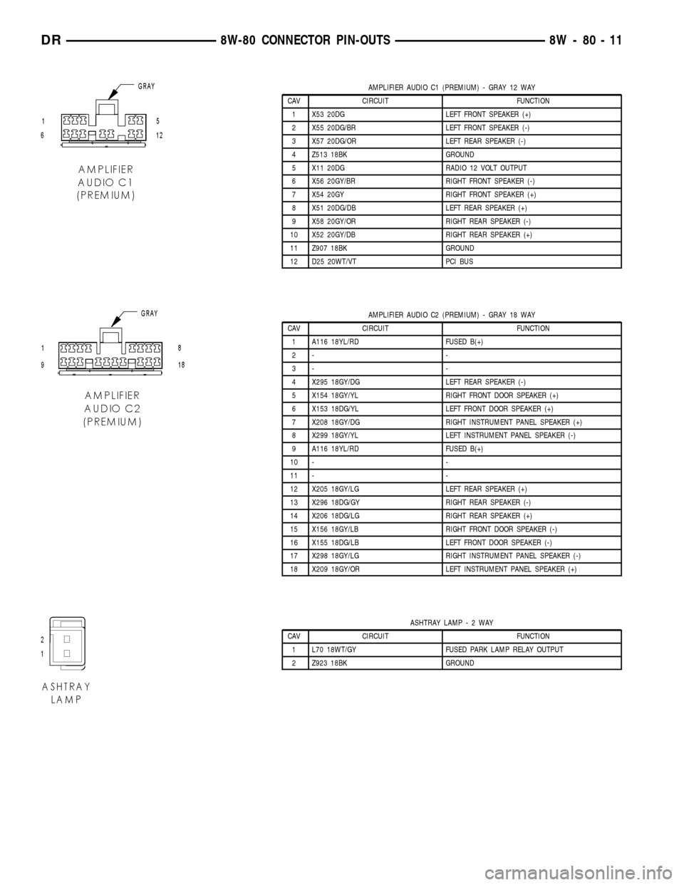
AMPLIFIER AUDIO C1 (PREMIUM) - GRAY 12 WAY
CAV CIRCUIT FUNCTION
1 X53 20DG LEFT FRONT SPEAKER (+)
2 X55 20DG/BR LEFT FRONT SPEAKER (-)
3 X57 20DG/OR LEFT REAR SPEAKER (-)
4 Z513 18BK GROUND
5 X11 20DG RADIO 12 VOLT OUTPUT
6 X56 20GY/BR RIGHT FRONT SPEAKER (-)
7 X54 20GY RIGHT FRONT SPEAKER (+)
8 X51 20DG/DB LEFT REAR SPEAKER (+)
9 X58 20GY/OR RIGHT REAR SPEAKER (-)
10 X52 20GY/DB RIGHT REAR SPEAKER (+)
11 Z907 18BK GROUND
12 D25 20WT/VT PCI BUS
AMPLIFIER AUDIO C2 (PREMIUM) - GRAY 18 WAY
CAV CIRCUIT FUNCTION
1 A116 18YL/RD FUSED B(+)
2- -
3- -
4 X295 18GY/DG LEFT REAR SPEAKER (-)
5 X154 18GY/YL RIGHT FRONT DOOR SPEAKER (+)
6 X153 18DG/YL LEFT FRONT DOOR SPEAKER (+)
7 X208 18GY/DG RIGHT INSTRUMENT PANEL SPEAKER (+)
8 X299 18GY/YL LEFT INSTRUMENT PANEL SPEAKER (-)
9 A116 18YL/RD FUSED B(+)
10 - -
11 - -
12 X205 18GY/LG LEFT REAR SPEAKER (+)
13 X296 18DG/GY RIGHT REAR SPEAKER (-)
14 X206 18DG/LG RIGHT REAR SPEAKER (+)
15 X156 18GY/LB RIGHT FRONT DOOR SPEAKER (-)
16 X155 18DG/LB LEFT FRONT DOOR SPEAKER (-)
17 X298 18GY/LG RIGHT INSTRUMENT PANEL SPEAKER (-)
18 X209 18GY/OR LEFT INSTRUMENT PANEL SPEAKER (+)
ASHTRAY LAMP-2WAY
CAV CIRCUIT FUNCTION
1 L70 18WT/GY FUSED PARK LAMP RELAY OUTPUT
2 Z923 18BK GROUND
DR8W-80 CONNECTOR PIN-OUTS 8W - 80 - 11
Page 1141 of 2627
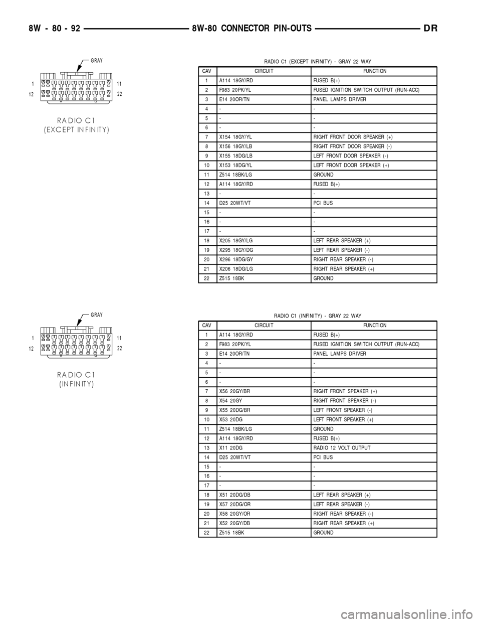
RADIO C1 (EXCEPT INFINITY) - GRAY 22 WAY
CAV CIRCUIT FUNCTION
1 A114 18GY/RD FUSED B(+)
2 F983 20PK/YL FUSED IGNITION SWITCH OUTPUT (RUN-ACC)
3 E14 20OR/TN PANEL LAMPS DRIVER
4- -
5- -
6- -
7 X154 18GY/YL RIGHT FRONT DOOR SPEAKER (+)
8 X156 18GY/LB RIGHT FRONT DOOR SPEAKER (-)
9 X155 18DG/LB LEFT FRONT DOOR SPEAKER (-)
10 X153 18DG/YL LEFT FRONT DOOR SPEAKER (+)
11 Z514 18BK/LG GROUND
12 A114 18GY/RD FUSED B(+)
13 - -
14 D25 20WT/VT PCI BUS
15 - -
16 - -
17 - -
18 X205 18GY/LG LEFT REAR SPEAKER (+)
19 X295 18GY/DG LEFT REAR SPEAKER (-)
20 X296 18DG/GY RIGHT REAR SPEAKER (-)
21 X206 18DG/LG RIGHT REAR SPEAKER (+)
22 Z515 18BK GROUND
RADIO C1 (INFINITY) - GRAY 22 WAY
CAV CIRCUIT FUNCTION
1 A114 18GY/RD FUSED B(+)
2 F983 20PK/YL FUSED IGNITION SWITCH OUTPUT (RUN-ACC)
3 E14 20OR/TN PANEL LAMPS DRIVER
4- -
5- -
6- -
7 X56 20GY/BR RIGHT FRONT SPEAKER (+)
8 X54 20GY RIGHT FRONT SPEAKER (-)
9 X55 20DG/BR LEFT FRONT SPEAKER (-)
10 X53 20DG LEFT FRONT SPEAKER (+)
11 Z514 18BK/LG GROUND
12 A114 18GY/RD FUSED B(+)
13 X11 20DG RADIO 12 VOLT OUTPUT
14 D25 20WT/VT PCI BUS
15 - -
16 - -
17 - -
18 X51 20DG/DB LEFT REAR SPEAKER (+)
19 X57 20DG/OR LEFT REAR SPEAKER (-)
20 X58 20GY/OR RIGHT REAR SPEAKER (-)
21 X52 20GY/DB RIGHT REAR SPEAKER (+)
22 Z515 18BK GROUND
8W - 80 - 92 8W-80 CONNECTOR PIN-OUTSDR
Page 1144 of 2627
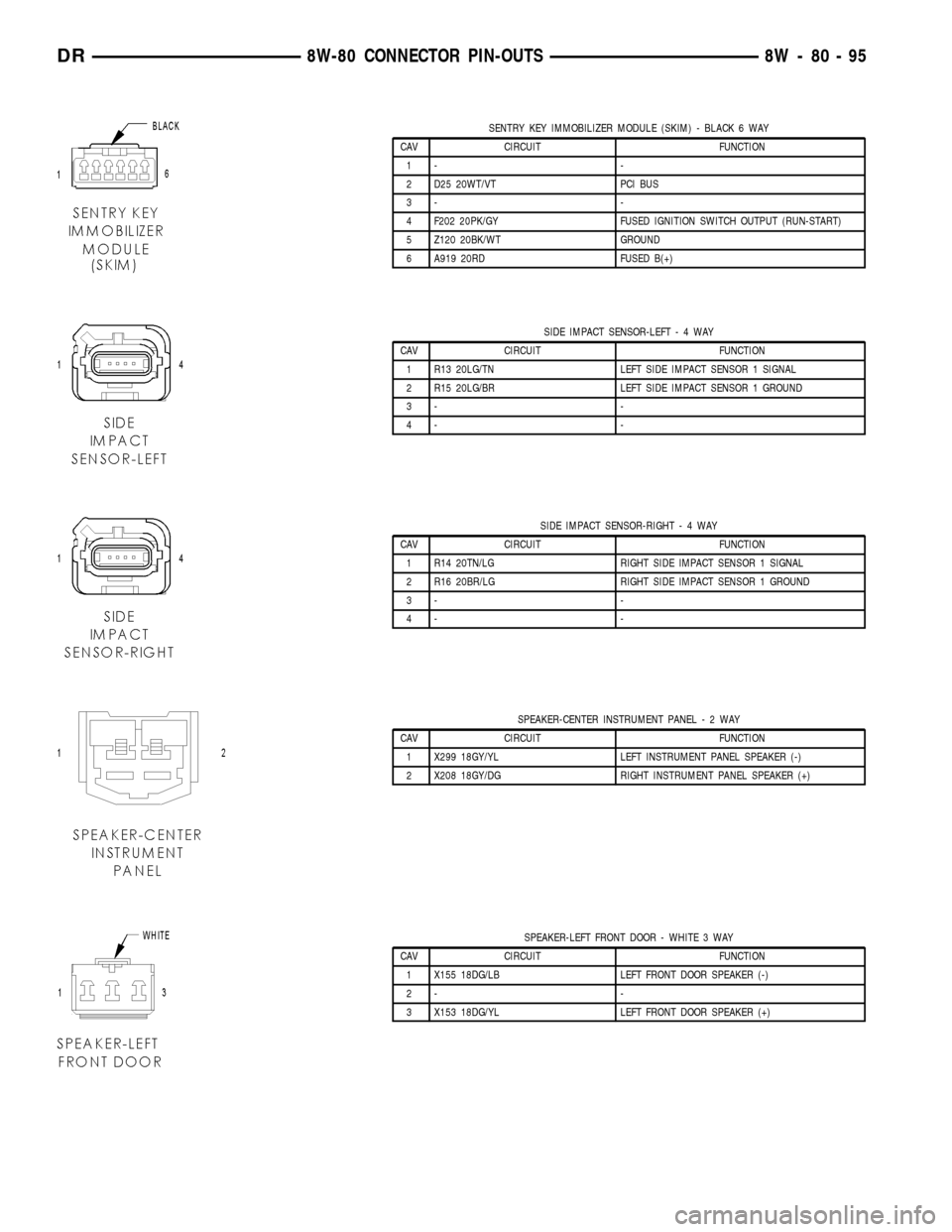
SENTRY KEY IMMOBILIZER MODULE (SKIM) - BLACK 6 WAY
CAV CIRCUIT FUNCTION
1- -
2 D25 20WT/VT PCI BUS
3- -
4 F202 20PK/GY FUSED IGNITION SWITCH OUTPUT (RUN-START)
5 Z120 20BK/WT GROUND
6 A919 20RD FUSED B(+)
SIDE IMPACT SENSOR-LEFT-4WAY
CAV CIRCUIT FUNCTION
1 R13 20LG/TN LEFT SIDE IMPACT SENSOR 1 SIGNAL
2 R15 20LG/BR LEFT SIDE IMPACT SENSOR 1 GROUND
3- -
4- -
SIDE IMPACT SENSOR-RIGHT-4WAY
CAV CIRCUIT FUNCTION
1 R14 20TN/LG RIGHT SIDE IMPACT SENSOR 1 SIGNAL
2 R16 20BR/LG RIGHT SIDE IMPACT SENSOR 1 GROUND
3- -
4- -
SPEAKER-CENTER INSTRUMENT PANEL-2WAY
CAV CIRCUIT FUNCTION
1 X299 18GY/YL LEFT INSTRUMENT PANEL SPEAKER (-)
2 X208 18GY/DG RIGHT INSTRUMENT PANEL SPEAKER (+)
SPEAKER-LEFT FRONT DOOR - WHITE 3 WAY
CAV CIRCUIT FUNCTION
1 X155 18DG/LB LEFT FRONT DOOR SPEAKER (-)
2- -
3 X153 18DG/YL LEFT FRONT DOOR SPEAKER (+)
DR8W-80 CONNECTOR PIN-OUTS 8W - 80 - 95
Page 1145 of 2627
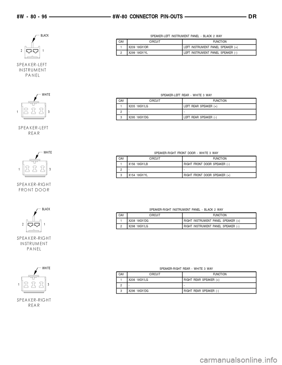
SPEAKER-LEFT INSTRUMENT PANEL - BLACK 2 WAY
CAV CIRCUIT FUNCTION
1 X209 18GY/OR LEFT INSTRUMENT PANEL SPEAKER (+)
2 X299 18GY/YL LEFT INSTRUMENT PANEL SPEAKER (-)
SPEAKER-LEFT REAR - WHITE 3 WAY
CAV CIRCUIT FUNCTION
1 X205 18GY/LG LEFT REAR SPEAKER (+)
2- -
3 X295 18GY/DG LEFT REAR SPEAKER (-)
SPEAKER-RIGHT FRONT DOOR - WHITE 3 WAY
CAV CIRCUIT FUNCTION
1 X156 18GY/LB RIGHT FRONT DOOR SPEAKER (-)
2- -
3 X154 18GY/YL RIGHT FRONT DOOR SPEAKER (+)
SPEAKER-RIGHT INSTRUMENT PANEL - BLACK 2 WAY
CAV CIRCUIT FUNCTION
1 X208 18GY/DG RIGHT INSTRUMENT PANEL SPEAKER (+)
2 X298 18GY/LG RIGHT INSTRUMENT PANEL SPEAKER (-)
SPEAKER-RIGHT REAR - WHITE 3 WAY
CAV CIRCUIT FUNCTION
1 X206 18GY/LG RIGHT REAR SPEAKER (+)
2- -
3 X296 18GY/DG RIGHT REAR SPEAKER (-)
8W - 80 - 96 8W-80 CONNECTOR PIN-OUTSDR
Page 1155 of 2627
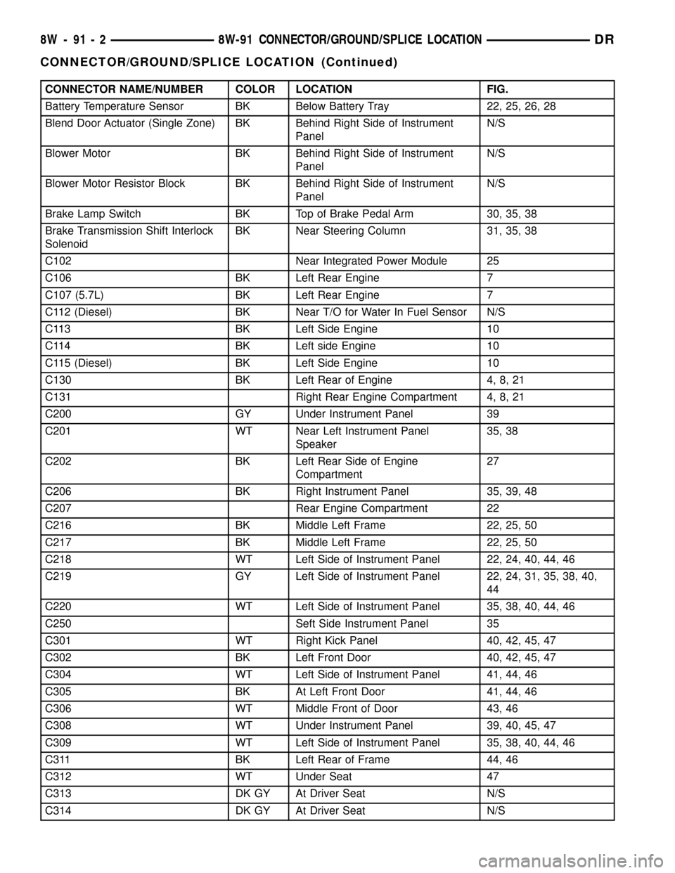
CONNECTOR NAME/NUMBER COLOR LOCATION FIG.
Battery Temperature Sensor BK Below Battery Tray 22, 25, 26, 28
Blend Door Actuator (Single Zone) BK Behind Right Side of Instrument
PanelN/S
Blower Motor BK Behind Right Side of Instrument
PanelN/S
Blower Motor Resistor Block BK Behind Right Side of Instrument
PanelN/S
Brake Lamp Switch BK Top of Brake Pedal Arm 30, 35, 38
Brake Transmission Shift Interlock
SolenoidBK Near Steering Column 31, 35, 38
C102 Near Integrated Power Module 25
C106 BK Left Rear Engine 7
C107 (5.7L) BK Left Rear Engine 7
C112 (Diesel) BK Near T/O for Water In Fuel Sensor N/S
C113 BK Left Side Engine 10
C114 BK Left side Engine 10
C115 (Diesel) BK Left Side Engine 10
C130 BK Left Rear of Engine 4, 8, 21
C131 Right Rear Engine Compartment 4, 8, 21
C200 GY Under Instrument Panel 39
C201 WT Near Left Instrument Panel
Speaker35, 38
C202 BK Left Rear Side of Engine
Compartment27
C206 BK Right Instrument Panel 35, 39, 48
C207 Rear Engine Compartment 22
C216 BK Middle Left Frame 22, 25, 50
C217 BK Middle Left Frame 22, 25, 50
C218 WT Left Side of Instrument Panel 22, 24, 40, 44, 46
C219 GY Left Side of Instrument Panel 22, 24, 31, 35, 38, 40,
44
C220 WT Left Side of Instrument Panel 35, 38, 40, 44, 46
C250 Seft Side Instrument Panel 35
C301 WT Right Kick Panel 40, 42, 45, 47
C302 BK Left Front Door 40, 42, 45, 47
C304 WT Left Side of Instrument Panel 41, 44, 46
C305 BK At Left Front Door 41, 44, 46
C306 WT Middle Front of Door 43, 46
C308 WT Under Instrument Panel 39, 40, 45, 47
C309 WT Left Side of Instrument Panel 35, 38, 40, 44, 46
C311 BK Left Rear of Frame 44, 46
C312 WT Under Seat 47
C313 DK GY At Driver Seat N/S
C314 DK GY At Driver Seat N/S
8W - 91 - 2 8W-91 CONNECTOR/GROUND/SPLICE LOCATIONDR
CONNECTOR/GROUND/SPLICE LOCATION (Continued)
Page 1160 of 2627

CONNECTOR NAME/NUMBER COLOR LOCATION FIG.
PTO Switch Near G107 N/S
Radio C1 (Base) GY Rear of Radio 35, 36
Radio C1 (Premium) BK Rear of Radio 36
Radio C2 (Premium) BK Rear of Radio 36
Radio Antenna - At Antenna Base 37
Radio Antenna Cable - Right Kick Panel 36, 37
Recirculation Door Actuator BK Right Side of HVAC N/S
Red Brake Warning Indicator
SwitchBK Near Master Cylinder 22, 25, 29
Remote Radio Switch-Left BK At Steering Wheel N/S
Remote Radio Switch-Right BK At Steering Wheel N/S
Seat Belt Pretensioner-Left YL Left B-Pillar 44, 46
Seat Belt Pretensioner-Right YL Right B-Pillar 45, 47
Seat Belt Switch-Driver DK GY Left B-Pillar N/S
Seat Belt Tension Reducer
(Standard Cab)YL Left B-Pillar 44
Seat Heater Interface Module GN Under Driver Seat N/S
Sentry Key Immobilizer Module BK On Steering Column 30
Side Marker - Left Front (Dual
Wheels)BK Front of Left Rear Fender 52
Side Marker - Left Rear (Dual
Wheels)BK Rear of Left Rear Fender 52
Side Marker - Right Front (Dual
Wheels)BK Front of Right Rear Fender 52
Side Marker - Right Rear (Dual
Wheels)BK Rear of Right Rear Fender 52
Speaker-Center Instrument Panel WT Center of Instrument Panel 35, 36
Speaker-Left Front Door WT In Left Front Door 41
Speaker-Left Instrument Panel BK Left Side of Instrument Panel 35, 38
Speaker-Left Rear (Standard Cab) WT In Lower Left B-Pillar 44
Speaker-Left Rear Door (Quad
Cab)WT In Left Rear Door 43
Speaker-Right Front Door WT In Right Front Door 42
Speaker-Right Instrument Panel BK Right Side of Instrument Panel 35, 39
Speaker-Right Rear (Standard
Cab)BK In Lower Right B-Pillar 45
Speaker-Right Rear Door (Quad
Cab)BK In Right Rear Door 43
Speed Control Servo BK Left Front Side of Engine
Compartment23, 25
Speed Control Switch - Left
(Except ETC)GN Steering Wheel N/S
Speed Control Switch - Right
(Except ETC)GN Steering Wheel N/S
Speed Control Switch-Left (ETC) WT At Steering Wheel N/S
DR8W-91 CONNECTOR/GROUND/SPLICE LOCATION 8W - 91 - 7
CONNECTOR/GROUND/SPLICE LOCATION (Continued)
Page 2320 of 2627
(5) Install the interior handle. (Refer to 23 -
BODY/DOOR - FRONT/INSIDE HANDLE ACTUA-
TOR - INSTALLATION)
(6) Install the window crank, if equipped.
WATERDAM
REMOVAL
CAUTION: Do not allow the waterdam or adhesive
to become contaminated with dirt or other foreign
substances.
Do not damage the waterdam during removal and
installation.
If the waterdam becomes contaminated or dam-
aged, replace the waterdam.
(1) Remove the inside handle actuator. (Refer to 23
- BODY/DOOR - FRONT/INSIDE HANDLE ACTUA-
TOR - REMOVAL)
(2) Remove the speaker. (Refer to 8 - ELECTRI-
CAL/AUDIO/SPEAKER - REMOVAL)
(3) Separate the waterdam from the inner door
panel and off of the latch linkages.
INSTALLATION
CAUTION: Do not allow the waterdam or adhesive
to become contaminated with dirt or other foreign
substances.
Do not damage the waterdam during removal and
installation.
If the waterdam becomes contaminated or dam-
aged, replace the waterdam.(1) Position the wire harness and actuator rods
through the holes in the waterdam.
(2) Secure the waterdam to the inner door panel.
(3) Install the speaker. (Refer to 8 - ELECTRICAL/
AUDIO/SPEAKER - INSTALLATION)
(4) Install the inside handle actuator. (Refer to 23 -
BODY/DOOR - FRONT/INSIDE HANDLE ACTUA-
TOR - INSTALLATION)
WINDOW REGULATOR -
POWER
REMOVAL
(1) Remove the waterdam. (Refer to 23 - BODY/
DOOR - FRONT/WATERDAM - REMOVAL)
(2) Remove the window switch from the door trim
panel and reconnect it to the door harness.
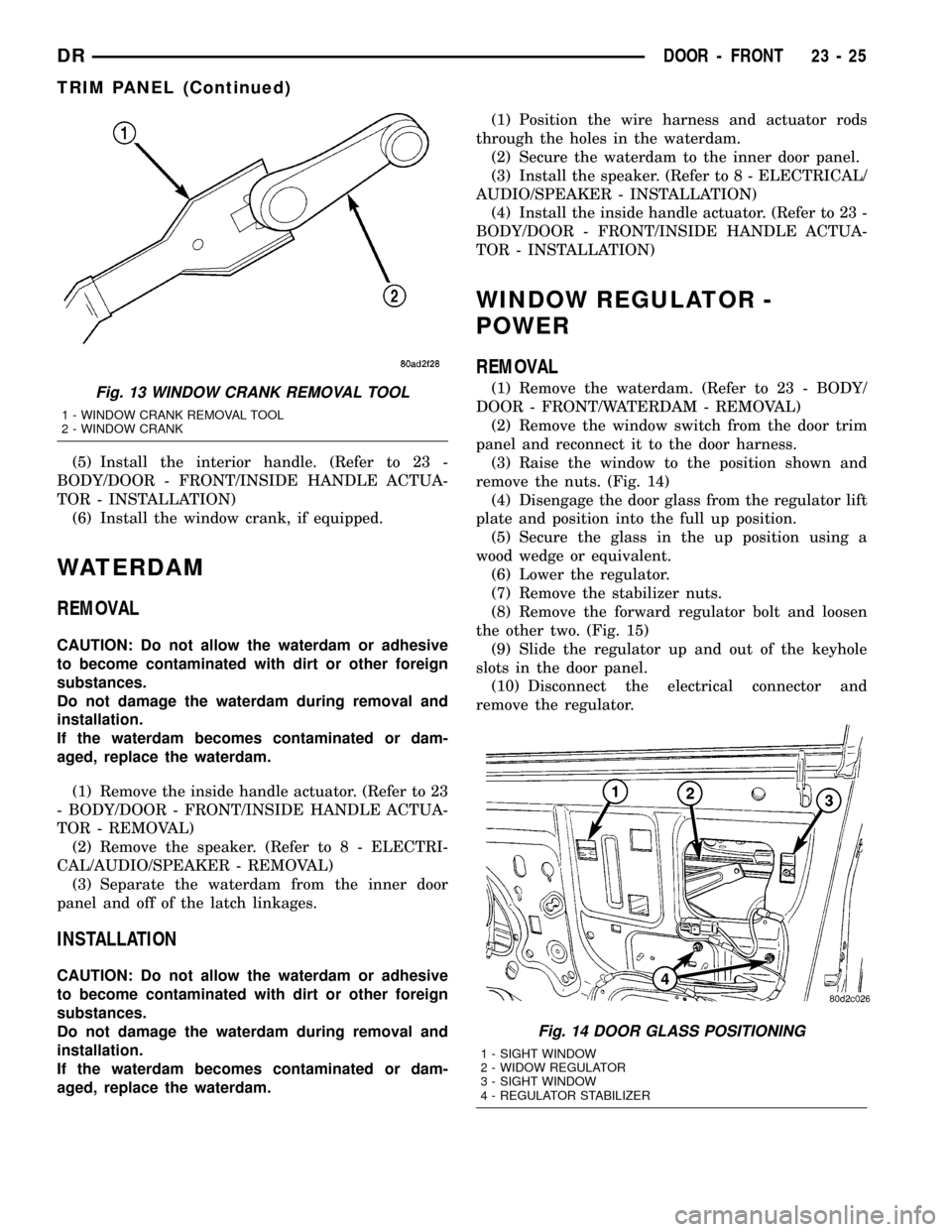
(3) Raise the window to the position shown and
remove the nuts. (Fig. 14)
(4) Disengage the door glass from the regulator lift
plate and position into the full up position.
(5) Secure the glass in the up position using a
wood wedge or equivalent.
(6) Lower the regulator.
(7) Remove the stabilizer nuts.
(8) Remove the forward regulator bolt and loosen
the other two. (Fig. 15)
(9) Slide the regulator up and out of the keyhole
slots in the door panel.
(10) Disconnect the electrical connector and
remove the regulator.Fig. 13 WINDOW CRANK REMOVAL TOOL
1 - WINDOW CRANK REMOVAL TOOL
2 - WINDOW CRANK
Fig. 14 DOOR GLASS POSITIONING
1 - SIGHT WINDOW
2 - WIDOW REGULATOR
3 - SIGHT WINDOW
4 - REGULATOR STABILIZER
DRDOOR - FRONT 23 - 25
TRIM PANEL (Continued)
Page 2329 of 2627
(4) Install the interior handle. (Refer to 23 -
BODY/DOORS - REAR/INSIDE HANDLE ACTUA-
TOR - INSTALLATION)
(5) Install the window crank, if equipped.
WATERDAM
REMOVAL
(1) Remove the inside handle actuator. (Refer to 23
- BODY/DOORS - REAR/INSIDE HANDLE ACTUA-
TOR - REMOVAL)
(2) Remove the speaker. (Refer to 8 - ELECTRI-
CAL/AUDIO/SPEAKER - REMOVAL)
(3) Separate the waterdam from the inner door
panel and off of the latch linkages.
INSTALLATION
(1) Position the wire harness and actuator rods
through the holes in the waterdam.
(2) Secure the waterdam to the inner door panel.
(3) Install the speaker. (Refer to 8 - ELECTRICAL/
AUDIO/SPEAKER - INSTALLATION)
(4) Install the inside handle actuator. (Refer to 23 -
BODY/DOORS - REAR/INSIDE HANDLE ACTUA-
TOR - INSTALLATION)
WINDOW REGULATOR -
POWER
REMOVAL
(1) Remove the waterdam. (Refer to 23 - BODY/
DOORS - REAR/WATERDAM - REMOVAL)
(2) Remove the window switch from the door trim
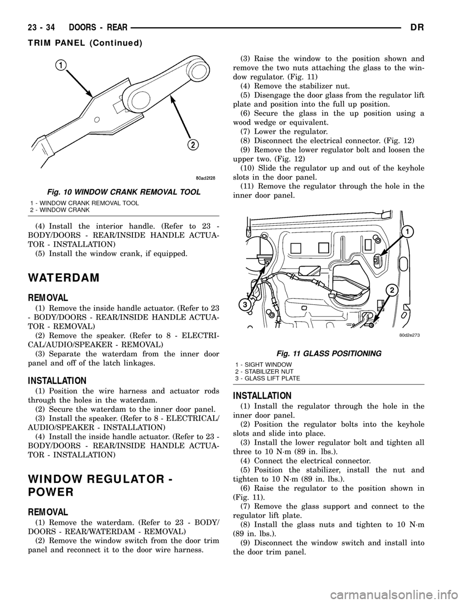
panel and reconnect it to the door wire harness.(3) Raise the window to the position shown and
remove the two nuts attaching the glass to the win-
dow regulator. (Fig. 11)
(4) Remove the stabilizer nut.
(5) Disengage the door glass from the regulator lift
plate and position into the full up position.
(6) Secure the glass in the up position using a
wood wedge or equivalent.
(7) Lower the regulator.
(8) Disconnect the electrical connector. (Fig. 12)
(9) Remove the lower regulator bolt and loosen the
upper two. (Fig. 12)
(10) Slide the regulator up and out of the keyhole
slots in the door panel.
(11) Remove the regulator through the hole in the
inner door panel.
INSTALLATION
(1) Install the regulator through the hole in the
inner door panel.
(2) Position the regulator bolts into the keyhole
slots and slide into place.
(3) Install the lower regulator bolt and tighten all
three to 10 N´m (89 in. lbs.).
(4) Connect the electrical connector.
(5) Position the stabilizer, install the nut and
tighten to 10 N´m (89 in. lbs.).
(6) Raise the regulator to the position shown in
(Fig. 11).
(7) Remove the glass support and connect to the
regulator lift plate.
(8) Install the glass nuts and tighten to 10 N´m
(89 in. lbs.).
(9) Disconnect the window switch and install into
the door trim panel.
Fig. 10 WINDOW CRANK REMOVAL TOOL
1 - WINDOW CRANK REMOVAL TOOL
2 - WINDOW CRANK
Fig. 11 GLASS POSITIONING
1 - SIGHT WINDOW
2 - STABILIZER NUT
3 - GLASS LIFT PLATE
23 - 34 DOORS - REARDR
TRIM PANEL (Continued)