Engine torque spec DODGE RAM 1500 1998 2.G Owner's Manual
[x] Cancel search | Manufacturer: DODGE, Model Year: 1998, Model line: RAM 1500, Model: DODGE RAM 1500 1998 2.GPages: 2627
Page 455 of 2627

INSTALLATION
3.7L / 4.7L
(1) Position generator to engine and install 2 hor-
izontal bolts and 1 vertical bolt.
(2) Tighten all 3 bolts. Refer to Torque Specifica-
tions.
(3) Snap field wire connector into rear of genera-
tor.
(4) Install B+ terminal eyelet to generator output
stud. Tighten mounting nut. Refer to Torque Specifi-
cations.
CAUTION: Never force a belt over a pulley rim
using a screwdriver. The synthetic fiber of the belt
can be damaged.
CAUTION: When installing a serpentine accessory
drive belt, the belt MUST be routed correctly. The
water pump may be rotating in the wrong direction
if the belt is installed incorrectly, causing the
engine to overheat. Refer to belt routing label in
engine compartment, or refer to Belt Schematics in
7, Cooling System.
(5) Install generator drive belt. Refer to 7, Cooling
System for procedure.
(6) Install negative battery cable to battery.5.7L
(1) Position generator to engine and install 2
mounting bolts.
(2) Tighten bolts. Refer to Torque Specifications.
(3) Position support bracket to front of generator
and install bolt and nuts. Tighten bolt / nuts. Refer
to Torque Specifications.
(4) Snap field wire connector into rear of genera-
tor.
(5) Install B+ terminal eyelet to generator output
stud. Tighten mounting nut. Refer to Torque Specifi-
cations.
CAUTION: Never force a belt over a pulley rim
using a screwdriver. The synthetic fiber of the belt
can be damaged.
CAUTION: When installing a serpentine accessory
drive belt, the belt MUST be routed correctly. The
water pump may be rotating in the wrong direction
if the belt is installed incorrectly, causing the
engine to overheat. Refer to belt routing label in
engine compartment, or refer to Belt Schematics in
7, Cooling System.
(6) Install generator drive belt. Refer to 7, Cooling
System for procedure.
(7) Install negative battery cable to battery.
5.9L Diesel
(1) Position generator to upper and lower mount-
ing brackets and install upper bolt and lower bolt /
nut.
(2) Tighten all bolts / nut. Refer to Torque Specifi-
cations.
(3) Snap field wire connector into rear of genera-
tor.
(4) Install B+ terminal eyelet to generator output
stud. Tighten mounting nut. Refer to Torque Specifi-
cations.
CAUTION: Never force a belt over a pulley rim
using a screwdriver. The synthetic fiber of the belt
can be damaged.
CAUTION: When installing a serpentine accessory
drive belt, the belt MUST be routed correctly. The
water pump may be rotating in the wrong direction
if the belt is installed incorrectly, causing the
engine to overheat. Refer to belt routing label in
engine compartment, or refer to Belt Schematics in
7, Cooling System.
(5) Install generator drive belt. Refer to 7, Cooling
System for procedure.
Fig. 7 5.9L DIESEL GENER. CONNECTORS
1 - B+ CONNECTOR
2 - GENERATOR
3 - FIELD WIRE CONNECTOR
8F - 24 CHARGINGDR
GENERATOR (Continued)
Page 457 of 2627

STARTING
TABLE OF CONTENTS
page page
STARTING
DESCRIPTION.........................26
OPERATION...........................26
DIAGNOSIS AND TESTING - STARTING
SYSTEM............................27
SPECIFICATIONS
STARTING SYSTEM...................31
SPECIFICATIONS - TORQUE - STARTING
SYSTEM............................32
STARTER MOTOR
DIAGNOSIS AND TESTING - STARTER
MOTOR .............................32REMOVAL.............................33
INSTALLATION.........................34
STARTER MOTOR RELAY
DESCRIPTION.........................35
OPERATION...........................36
DIAGNOSIS AND TESTING - STARTER RELAY . 36
REMOVAL.............................37
INSTALLATION.........................37
STARTING
DESCRIPTION
The starting system consists of:
²Starter relay
²Starter motor (including an integral starter sole-
noid)
Other components to be considered as part of start-
ing system are:
²Battery
²Battery cables
²Ignition switch and key lock cylinder
²Clutch pedal position switch (manual transmis-
sion)
²Park/neutral position switch (automatic trans-
mission)
²Wire harnesses and connections.
The Battery, Starting, and Charging systems oper-
ate in conjunction with one another, and must be
tested as a complete system. For correct operation of
starting/charging systems, all components used in
these 3 systems must perform within specifications.
When attempting to diagnose any of these systems, it
is important that you keep their interdependency in
mind.
The diagnostic procedures used in each of these
groups include the most basic conventional diagnostic
methods, to the more sophisticated On-Board Diag-
nostics (OBD) built into the Powertrain Control Mod-
ule (PCM). Use of an induction-type milliampere
ammeter, volt/ohmmeter, battery charger, carbon pile
rheostat (load tester), and 12-volt test lamp may be
required.Certain starting system components are monitored
by the PCM and may produce a Diagnostic Trouble
Code (DTC). Refer to Diagnostic Trouble Codes in
Emission Control for a list of codes.
OPERATION
The starting system components form two separate
circuits. A high-amperage feed circuit that feeds the
starter motor between 150 and 350 amperes (700
amperes - diesel engine), and a low-amperage control
circuit that operates on less than 20 amperes. The
high-amperage feed circuit components include the
battery, the battery cables, the contact disc portion of
the starter solenoid, and the starter motor. The low-
amperage control circuit components include the igni-
tion switch, the clutch pedal position switch (manual
transmission), the park/neutral position switch (auto-
matic transmission), the starter relay, the electro-
magnetic windings of the starter solenoid, and the
connecting wire harness components.
If the vehicle is equipped with a manual transmis-
sion, it has a clutch pedal position switch installed in
series between the ignition switch and the coil bat-
tery terminal of the starter relay. This normally open
switch prevents the starter relay from being ener-
gized when the ignition switch is turned to the Start
position, unless the clutch pedal is depressed. This
feature prevents starter motor operation while the
clutch disc and the flywheel are engaged. The starter
relay coil ground terminal is always grounded on
vehicles with a manual transmission.
8F - 26 STARTINGDR
Page 459 of 2627

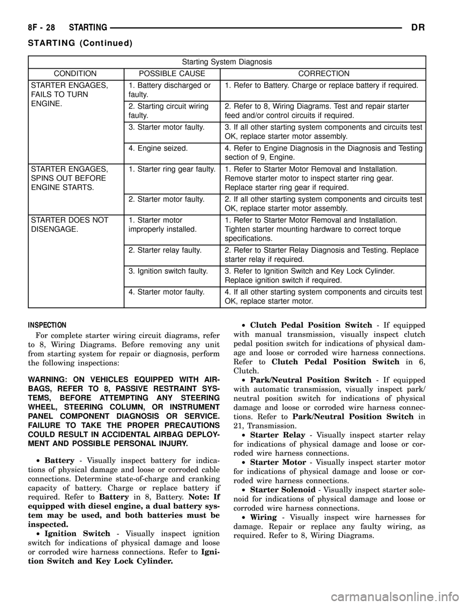
Starting System Diagnosis
CONDITION POSSIBLE CAUSE CORRECTION
STARTER ENGAGES,
FAILS TO TURN
ENGINE.1. Battery discharged or
faulty.1. Refer to Battery. Charge or replace battery if required.
2. Starting circuit wiring
faulty.2. Refer to 8, Wiring Diagrams. Test and repair starter
feed and/or control circuits if required.
3. Starter motor faulty. 3. If all other starting system components and circuits test
OK, replace starter motor assembly.
4. Engine seized. 4. Refer to Engine Diagnosis in the Diagnosis and Testing
section of 9, Engine.
STARTER ENGAGES,
SPINS OUT BEFORE
ENGINE STARTS.1. Starter ring gear faulty. 1. Refer to Starter Motor Removal and Installation.
Remove starter motor to inspect starter ring gear.
Replace starter ring gear if required.
2. Starter motor faulty. 2. If all other starting system components and circuits test
OK, replace starter motor assembly.
STARTER DOES NOT
DISENGAGE.1. Starter motor
improperly installed.1. Refer to Starter Motor Removal and Installation.
Tighten starter mounting hardware to correct torque
specifications.
2. Starter relay faulty. 2. Refer to Starter Relay Diagnosis and Testing. Replace
starter relay if required.
3. Ignition switch faulty. 3. Refer to Ignition Switch and Key Lock Cylinder.
Replace ignition switch if required.
4. Starter motor faulty. 4. If all other starting system components and circuits test
OK, replace starter motor.
INSPECTION
For complete starter wiring circuit diagrams, refer
to 8, Wiring Diagrams. Before removing any unit
from starting system for repair or diagnosis, perform
the following inspections:
WARNING: ON VEHICLES EQUIPPED WITH AIR-
BAGS, REFER TO 8, PASSIVE RESTRAINT SYS-
TEMS, BEFORE ATTEMPTING ANY STEERING
WHEEL, STEERING COLUMN, OR INSTRUMENT
PANEL COMPONENT DIAGNOSIS OR SERVICE.
FAILURE TO TAKE THE PROPER PRECAUTIONS
COULD RESULT IN ACCIDENTAL AIRBAG DEPLOY-
MENT AND POSSIBLE PERSONAL INJURY.
²Battery- Visually inspect battery for indica-
tions of physical damage and loose or corroded cable
connections. Determine state-of-charge and cranking
capacity of battery. Charge or replace battery if
required. Refer toBatteryin 8, Battery.Note: If
equipped with diesel engine, a dual battery sys-
tem may be used, and both batteries must be
inspected.
²Ignition Switch- Visually inspect ignition
switch for indications of physical damage and loose
or corroded wire harness connections. Refer toIgni-
tion Switch and Key Lock Cylinder.²Clutch Pedal Position Switch- If equipped
with manual transmission, visually inspect clutch
pedal position switch for indications of physical dam-
age and loose or corroded wire harness connections.
Refer toClutch Pedal Position Switchin 6,
Clutch.
²Park/Neutral Position Switch- If equipped
with automatic transmission, visually inspect park/
neutral position switch for indications of physical
damage and loose or corroded wire harness connec-
tions. Refer toPark/Neutral Position Switchin
21, Transmission.
²Starter Relay- Visually inspect starter relay
for indications of physical damage and loose or cor-
roded wire harness connections.
²Starter Motor- Visually inspect starter motor
for indications of physical damage and loose or cor-
roded wire harness connections.
²Starter Solenoid- Visually inspect starter sole-
noid for indications of physical damage and loose or
corroded wire harness connections.
²Wiring- Visually inspect wire harnesses for
damage. Repair or replace any faulty wiring, as
required. Refer to 8, Wiring Diagrams.
8F - 28 STARTINGDR
STARTING (Continued)
Page 463 of 2627

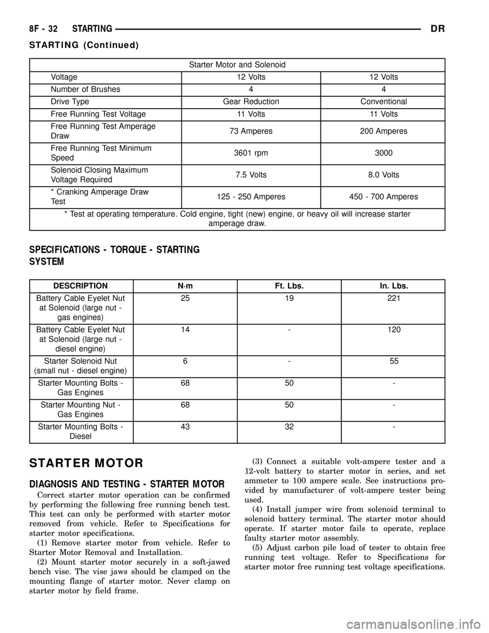
Starter Motor and Solenoid
Voltage 12 Volts 12 Volts
Number of Brushes 4 4
Drive Type Gear Reduction Conventional
Free Running Test Voltage 11 Volts 11 Volts
Free Running Test Amperage
Draw73 Amperes 200 Amperes
Free Running Test Minimum
Speed3601 rpm 3000
Solenoid Closing Maximum
Voltage Required7.5 Volts 8.0 Volts
* Cranking Amperage Draw
Test125 - 250 Amperes 450 - 700 Amperes
* Test at operating temperature. Cold engine, tight (new) engine, or heavy oil will increase starter
amperage draw.
SPECIFICATIONS - TORQUE - STARTING
SYSTEM
DESCRIPTION N´m Ft. Lbs. In. Lbs.
Battery Cable Eyelet Nut
at Solenoid (large nut -
gas engines)25 19 221
Battery Cable Eyelet Nut
at Solenoid (large nut -
diesel engine)14 - 120
Starter Solenoid Nut
(small nut - diesel engine)6-55
Starter Mounting Bolts -
Gas Engines68 50 -
Starter Mounting Nut -
Gas Engines68 50 -
Starter Mounting Bolts -
Diesel43 32 -
STARTER MOTOR
DIAGNOSIS AND TESTING - STARTER MOTOR
Correct starter motor operation can be confirmed
by performing the following free running bench test.
This test can only be performed with starter motor
removed from vehicle. Refer to Specifications for
starter motor specifications.
(1) Remove starter motor from vehicle. Refer to
Starter Motor Removal and Installation.
(2) Mount starter motor securely in a soft-jawed
bench vise. The vise jaws should be clamped on the
mounting flange of starter motor. Never clamp on
starter motor by field frame.(3) Connect a suitable volt-ampere tester and a
12-volt battery to starter motor in series, and set
ammeter to 100 ampere scale. See instructions pro-
vided by manufacturer of volt-ampere tester being
used.
(4) Install jumper wire from solenoid terminal to
solenoid battery terminal. The starter motor should
operate. If starter motor fails to operate, replace
faulty starter motor assembly.
(5) Adjust carbon pile load of tester to obtain free
running test voltage. Refer to Specifications for
starter motor free running test voltage specifications.
8F - 32 STARTINGDR
STARTING (Continued)
Page 465 of 2627

5.7L Gas
(1) Disconnect and isolate negative battery cable.
(2) Raise and support vehicle.
(3) Note: If equipped with 4WD and certain trans-
missions, a support bracket is used between front
axle and side of transmission. Remove 2 support
bracket bolts at transmission. Pry support bracket
slightly to gain access to lower starter mounting bolt.
(4) Remove 2 mounting bolts (Fig. 11).
(5) Move starter motor towards front of vehicle far
enough for nose of starter pinion housing to clear
housing. Always support starter motor during this
process, do not let starter motor hang from wire har-
ness.
(6) Tilt nose downwards and lower starter motor
far enough to access and remove nut that secures
battery positive cable wire harness connector eyelet
to solenoid battery terminal stud. Do not let starter
motor hang from wire harness.
(7) Remove battery positive cable wire harness
connector eyelet from solenoid battery terminal stud.
(8) Disconnect battery positive cable wire harness
connector from solenoid terminal connector recepta-
cle.
(9) Remove starter motor.
5.9L Diesel
(1) Disconnect and isolate both negative battery
cables at both batteries.
(2) Raise and support vehicle.
(3) Remove 3 starter mounting bolts (Fig. 12).(4) Move starter motor towards front of vehicle far
enough for nose of starter pinion housing to clear
housing. Always support starter motor during this
process. Do not let starter motor hang from wire har-
ness.
(5) Tilt nose downwards and lower starter motor
far enough to access and remove nuts securing
starter wiring harness to starter (Fig. 13). Do not let
starter motor hang from wire harness.
(6) Remove starter motor from engine. Note: Cer-
tain diesel engines use an aluminum spacer (Fig. 12).
Note position and orientation of spacer before
removal.
INSTALLATION
3.7L / 4.7L
(1) Connect solenoid wire to starter motor (snaps
on).
(2) Position battery cable to solenoid stud. Install
and tighten battery cable eyelet nut. Refer to Torque
Specifications. Do not allow starter motor to hang
from wire harness.
(3) Position starter motor to transmission.
(4) If equipped with automatic transmission, slide
cooler tube bracket into position.
(5) Install and tighten both bolts (auto. trans.), or
1 nut and 1 bolt (man. trans.). Refer to Torque Spec-
ifications.
(6) Lower vehicle.
(7) Connect negative battery cable.
Fig. 10 STARTER R/I - 3.7L/4.7L - AUTO. TRANS.
1 - EYELET TERMINAL
2 - NUT
3 - SCREW AND WASHER (2)
4 - STARTER MOTOR
5 - WIRE HARNESS CONNECTOR
Fig. 11 STARTER R/I - 5.7L
1 - STARTER MOTOR
2 - MOUNTING BOLTS
8F - 34 STARTINGDR
STARTER MOTOR (Continued)
Page 466 of 2627

5.7L
(1) Connect solenoid wire to starter motor (snaps
on).
(2) Position battery cable to solenoid stud. Install
and tighten battery cable eyelet nut. Refer to Torque
Specifications. Do not allow starter motor to hang
from wire harness.
(3) Position starter motor to engine.
(4) If equipped with automatic transmission, slide
cooler tube bracket into position.
(5) Install and tighten both mounting bolts. Refer
to Torque Specifications.
(6) Lower vehicle.
(7) Connect negative battery cable.
5.9L Diesel
(1)If Equipped:Position and hold aluminum
spacer to rear of starter while positioning starter to
engine.
(2) Connect solenoid wire to starter motor. Tighten
nut.
(3) Position battery cable to starter stud. Install
and tighten battery cable nut. Refer to Torque Spec-
ifications. Do not allow starter motor to hang from
wire harness.
(4) Position starter motor to transmission.
(5) If equipped with automatic transmission, slide
cooler tube bracket into position.
(6) Install and tighten 3 starter mounting bolts.
Refer to Torque Specifications.
(7) Lower vehicle.
(8) Connect both negative battery cables to both
batteries.
STARTER MOTOR RELAY
DESCRIPTION
The starter relay is an electromechanical device
that switches battery current to the pull-in coil of the
starter solenoid when ignition switch is turned to
Start position. The starter relay is located in the
Power Distribution Center (PDC) in the engine com-
partment. See PDC cover for relay identification and
location.
The starter relay is a International Standards
Organization (ISO) relay. Relays conforming to ISO
specifications have common physical dimensions, cur-
rent capacities, terminal patterns, and terminal func-
tions.
The starter relay cannot be repaired or adjusted. If
faulty or damaged, it must be replaced.
Fig. 12 STARTER R/I - 5.9L DIESEL
1 - MOUNTING BOLTS (3)
2 - STARTER MOTOR
3 - SPACER (CERTAIN TRANSMISSIONS)
Fig. 13 STARTER ELECTRICAL CONNECTORS -
5.9L DIESEL
1 - STARTER MOTOR
2 - BATTERY CABLE NUT
3 - SOLENOID NUT
4 - HARNESS ASSEMBLY
DRSTARTING 8F - 35
STARTER MOTOR (Continued)
Page 488 of 2627

IGNITION CONTROL
TABLE OF CONTENTS
page page
IGNITION CONTROL
DESCRIPTION..........................1
SPECIFICATIONS
SPECIFICATIONS - TORQUE - IGNITION....3
ENGINE FIRING ORDER - 3.7L V-6.........4
ENGINE FIRING ORDER ± 4.7L V-8........4
FIRING ORDER / CABLE ROUTING ± 5.7L
V-8 ENGINE...........................4
SPARK PLUG CABLE RESISTANCE........4
SPARK PLUGS........................4
IGNITION COIL RESISTANCE - 3.7L V-6.....5
IGNITION COIL RESISTANCE - 4.7L V-8.....5
IGNITION COIL RESISTANCE - 5.7L V-8.....5
IGNITION TIMING......................5
AUTOMATIC SHUT DOWN RELAY
DESCRIPTION - PCM OUTPUT.............5
OPERATION
OPERATION - PCM OUTPUT.............5
OPERATION - ASD SENSE - PCM INPUT....5
DIAGNOSIS AND TESTING - ASD AND FUEL
PUMP RELAYS........................5
REMOVAL.............................6
INSTALLATION..........................6
CAMSHAFT POSITION SENSOR
DESCRIPTION..........................7
OPERATION............................7
REMOVAL.............................9
INSTALLATION.........................10IGNITION COIL
DESCRIPTION.........................11
OPERATION...........................12
REMOVAL.............................13
INSTALLATION.........................14
KNOCK SENSOR
DESCRIPTION.........................14
OPERATION...........................14
REMOVAL.............................15
INSTALLATION.........................15
SPARK PLUG
DESCRIPTION.........................17
DIAGNOSIS AND TESTING - SPARK PLUG
CONDITIONS.........................17
REMOVAL.............................19
CLEANING
CLEANING AND ADJUSTMENT...........20
INSTALLATION.........................20
IGNITION COIL CAPACITOR
DESCRIPTION.........................21
OPERATION...........................21
REMOVAL.............................21
INSTALLATION.........................21
SPARK PLUG CABLE
DESCRIPTION.........................21
OPERATION...........................21
REMOVAL.............................22
INSTALLATION.........................22
IGNITION CONTROL
DESCRIPTION
The ignition system is controlled by the Powertrain
Control Module (PCM) on all engines.
3.7L V-6 ENGINE
The 3.7L V-6 engine uses a separate ignition coil
for each cylinder. The one-piece coil bolts directly to
the cylinder head. Rubber boots seal the secondary
terminal ends of the coils to the top of all 6 spark
plugs. A separate electrical connector is used for each
coil.
Because of coil design, spark plug cables (second-
ary cables) are not used. A distributor is not used
with the 3.7L engine.
Two knock sensors (one for each cylinder bank) are
used to help control spark knock.The Auto Shutdown (ASD) relay provides battery
voltage to each ignition coil.
The ignition system consists of:
²6 Spark Plugs
²6 Separate Ignition Coils
²2 Knock Sensors
²Powertrain Control Module (PCM)
²Also to be considered part of the ignition system
are certain inputs from the Crankshaft Position,
Camshaft Position, Throttle Position, 2 knock and
MAP Sensors
4.7L V-8 ENGINE
The 4.7L V-8 engine uses a separate ignition coil
for each cylinder. The one-piece coil bolts directly to
the cylinder head. Rubber boots seal the secondary
terminal ends of the coils to the top of all 8 spark
plugs. A separate electrical connector is used for each
coil.
DRIGNITION CONTROL 8I - 1
Page 490 of 2627

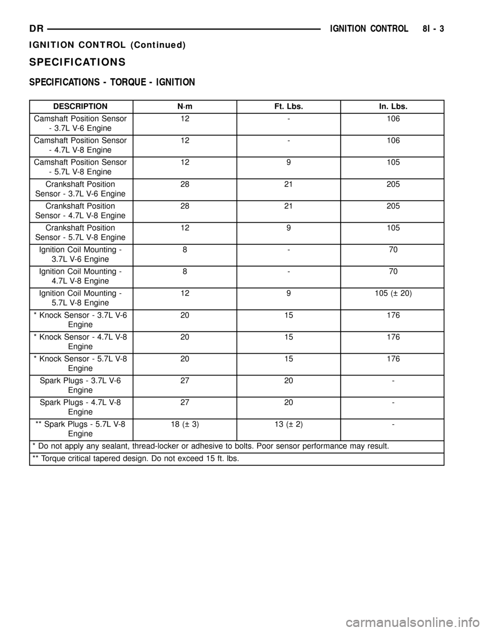
SPECIFICATIONS
SPECIFICATIONS - TORQUE - IGNITION
DESCRIPTION N´m Ft. Lbs. In. Lbs.
Camshaft Position Sensor
- 3.7L V-6 Engine12 - 106
Camshaft Position Sensor
- 4.7L V-8 Engine12 - 106
Camshaft Position Sensor
- 5.7L V-8 Engine12 9 105
Crankshaft Position
Sensor - 3.7L V-6 Engine28 21 205
Crankshaft Position
Sensor - 4.7L V-8 Engine28 21 205
Crankshaft Position
Sensor - 5.7L V-8 Engine12 9 105
Ignition Coil Mounting -
3.7L V-6 Engine8-70
Ignition Coil Mounting -
4.7L V-8 Engine8-70
Ignition Coil Mounting -
5.7L V-8 Engine12 9 105 ( 20)
* Knock Sensor - 3.7L V-6
Engine20 15 176
* Knock Sensor - 4.7L V-8
Engine20 15 176
* Knock Sensor - 5.7L V-8
Engine20 15 176
Spark Plugs - 3.7L V-6
Engine27 20 -
Spark Plugs - 4.7L V-8
Engine27 20 -
** Spark Plugs - 5.7L V-8
Engine18 ( 3) 13 ( 2) -
* Do not apply any sealant, thread-locker or adhesive to bolts. Poor sensor performance may result.
** Torque critical tapered design. Do not exceed 15 ft. lbs.
DRIGNITION CONTROL 8I - 3
IGNITION CONTROL (Continued)
Page 497 of 2627

5.9L Diesel
The Camshaft Position Sensor (CMP) on the 5.9L
diesel engine is located below the fuel injection
pump. It is bolted to the back of the timing gear
cover (Fig. 14).
(1) Disconnect electrical connector at CMP sensor
(Fig. 14).
(2) Remove sensor mounting bolt.
(3) Carefully twist sensor from timing gear cover.
(4) Check condition of sensor o-ring.
INSTALLATION
3.7L V-6
The Camshaft Position Sensor (CMP) on the 3.7L
V-6 engine is bolted to the front/top of the right cyl-
inder head (Fig. 10).
(1) Clean out machined hole in cylinder head.
(2) Apply a small amount of engine oil to sensor
o-ring.
(3) Install sensor into cylinder head with a slight
rocking and twisting action.
CAUTION: Before tightening sensor mounting bolt,
be sure sensor is completely flush to cylinder head.
If sensor is not flush, damage to sensor mounting
tang may result.
(4) Install mounting bolt and tighten. Refer to
torque specifications.(5) Connect electrical connector to sensor.
4.7L V-8
The Camshaft Position Sensor (CMP) on the 4.7L
V-8 engine is bolted to the front/top of the right cyl-
inder head (Fig. 11).
(1) Clean out machined hole in cylinder head.
(2) Apply a small amount of engine oil to sensor
o-ring.
(3) Install sensor into cylinder head with a slight
rocking action. Do not twist sensor into position as
damage to o-ring may result.
CAUTION: Before tightening sensor mounting bolt,
be sure sensor is completely flush to cylinder head.
If sensor is not flush, damage to sensor mounting
tang may result.
(4) Install mounting bolt and tighten. Refer to
Torque Specifications.
(5) Connect electrical connector to sensor.
5.7L V-8
The Camshaft Position Sensor (CMP) on the 5.7L
V-8 engine is bolted to the right / front side of the
timing chain cover (Fig. 12) or (Fig. 13).
(1) Clean out machined hole in cylinder head.
Fig. 13 CMP REMOVAL / INSTALLATION ± 5.7L V-8
1 - TIMING CHAIN COVER (RIGHT/FRONT)
2 - CMP SENSOR
3 - MOUNTING BOLT
Fig. 14 5.9L DIESEL CMP
1 - CMP
2 - FUEL INJECTION PUMP (BOTTOM)
3 - ELECTRONIC CONTROL MODULE (ECM)
4 - ECM ELEC. CONNECTOR
5 - CMP ELEC. CONNECTOR
6 - CMP MOUNTING BOLT
7 - BACK OF TIMING GEAR COVER
8I - 10 IGNITION CONTROLDR
CAMSHAFT POSITION SENSOR (Continued)
Page 498 of 2627

(2) Apply a small amount of engine oil to sensor
o-ring.
(3) Install sensor into cylinder head with a slight
rocking action. Do not twist sensor into position as
damage to o-ring may result.
CAUTION: Before tightening sensor mounting bolt,
be sure sensor is completely flush to timing chain
cover. If sensor is not flush, damage to sensor
mounting tang may result.
(4) Install mounting bolt and tighten. Refer to
Torque Specifications.
(5) Connect electrical connector to sensor.
5.9L Diesel
The CMP is located on the back of the timing gear
cover (Fig. 14).
(1) Clean out machined hole in back of timing gear
cover.
(2) Apply a small amount of engine oil to sensor
o-ring.
(3) Install sensor into timing gear cover with a
slight rocking action. Do not twist sensor into posi-
tion as damage to o-ring may result.
CAUTION: Before tightening sensor mounting bolt,
be sure sensor is completely flush to back of timing
chain cover. If sensor is not flush, damage to sen-
sor mounting tang may result.
(4) Install mounting bolt and tighten. Refer to
Torque Specifications.
(5) Connect electrical connector to sensor.
IGNITION COIL
DESCRIPTION
3.7L V-6
The 3.7L V-6 engine uses 6 dedicated, and individ-
ually fired coil for each spark plug (Fig. 15). Each
coil is mounted directly into the cylinder head and
onto the top of each spark plug (Fig. 16).
4.7L V-8
The 4.7L V±8 engine uses 8 dedicated, and individ-
ually fired coil (Fig. 15) for each spark plug. Each
coil is mounted directly to the top of each spark plug
(Fig. 17).
5.7L V-8
The 5.7L V±8 engine uses 8 dedicated, and individ-
ually fired coil (Fig. 18) for each pair of spark plugs.
Each coil is mounted directly to the top of each spark
plug (Fig. 19). Each coil is bolted to the valve cover.
Fig. 15 IGNITION COIL - 3.7L V-6/ 4.7L V-8
1 - O-RING
2 - IGNITION COIL
3 - ELECTRICAL CONNECTOR
Fig. 16 IGNITION COIL LOCATION - 3.7L V-6
1 - IGNITION COIL
2 - COIL MOUNTING NUT
DRIGNITION CONTROL 8I - 11
CAMSHAFT POSITION SENSOR (Continued)