Front wheel speed sensor DODGE RAM 1500 1998 2.G Owner's Manual
[x] Cancel search | Manufacturer: DODGE, Model Year: 1998, Model line: RAM 1500, Model: DODGE RAM 1500 1998 2.GPages: 2627
Page 424 of 2627

²Proper transmit/receive messages are occurring
on the PCI bus.
²Ignition key switch is in the RUN position.
Range shiftswill be allowed only if all of the fol-
lowing conditions are met:
²Front and rear wheel speed are within 21 km/hr
(13 mph).
²A change in the Selector Switch state indicating
a range shift has been requested.
²Transmission in NEUTRAL signal must be rec-
ognized for at least 1.5 seconds 100 msec. (Auto-
matic transmissions only)
²Proper transmit/receive messages are occurring
on the PCI bus.
²Clutch signal is recognized for 500 msec 50
msec (Manual transmissions only).
²Vehicle speed is less than or equal to 4.8 km/hr
(3 miles per hour).
²Ignition key switch is in the RUN position.
²A valid mode sensor signal is being sensed by
the TCCM.
Ashift into transfer case Neutralwill be
allowed only if all of the following conditions are met:
²Front and rear wheel speed are within 21 km/hr
(13 mph).
²The recessed Neutral Selection switch has been
depressed continuously for 4.0 seconds 100 msec
while all shift conditions have been continuously met.
²Transmission in NEUTRAL signal recognized
from the bus. (Automatic transmissions only)
²Clutch signal is recognized from the bus (Man-
ual transmissions only).
²Proper message transmissions/receptions are
occurring on the PCI bus.
²Vehicle speed is less than or equal to 4.8 km/hr
(3 miles per hour).
²Ignition key switch is in the RUN position,
engine off.
²Foot Brake is applied.
²A valid mode sensor signal is being sensed by
the TCCM.
Ashift out of transfer case Neutralwill be
allowed only if all of the following conditions are met:
²Front and rear wheel speed are within 21 km/hr
(13 mph).
²The recessed Neutral Selection switch has been
depressed continuously for 1.0 seconds 100 msec
while all shift conditions have been continuously met.
²Transmission in NEUTRAL signal recognized
from the bus.(Automatic transmissions only)
²Clutch signal is recognized from the bus (Man-
ual transmissions only).
²Proper message transmissions/receptions are
occurring on the PCI bus.
²Vehicle speed is less than or equal to 4.8 km/hr
(3 miles per hour).²Ignition key switch is in the RUN position.
²Foot Brake is applied.
²A valid mode sensor signal is being sensed by
the TCCM.
SHIFT SEQUENCES
Once all the driver controllable conditions for the
requested shift have been met, the TCCM begins a
shift timer with a maximum duration of 1 second per
'D' channel transition. If the shift timer expires
before the TCCM recognizes to correct mode sensor
code, the shift is considered to have been blocked.
The blocked shift will increment the blocked shift
counter by one. The TCCM strategy for handling
blocked shifts will be described later. The process the
TCCM performs for the various shifts will be
described first.
RANGE AND MODE SHIFTS
The process for performing all the range and mode
shifts are the same. The following steps describe the
process.
²Allow time for Selector Switch debounce; 250
msec 50 msec.
²Extinguish the source gear's LED while flashing
desired transfer case position's LED.
²Engage the shift motor for a maximum of 1 sec-
ond 100 msec per 'D' channel transition in the des-
tination gear's direction while monitoring the mode
sensor channel transitions.
²Disengage the shift motor when the correct
mode sensor code is recognized.
²Solidly illuminate the selected gear's LED.
²Transmit a bus message that the transfer case
shift is complete.
²If the desired mode sensor code is not received
after the shift timer expires (ie. a blocked or other
condition exists), stop driving the motor and wait for
200 msec 50 msec. The shift motor is then reversed
in the direction back toward the source gear for up to
1.0 seconds 100 msec. per 'D' channel. The TCCM
waits for 2.0 seconds 50 msec. and repeats the
attempt to shift to the desired position.
The exception to the preceding sequence is when a
shift from 4L to 2WD/AWD is requested. If 2WD/
AWD is requested from the 4L position, the transfer
case is first driven to the 4H position. If the 4H posi-
tion is reached, the transfer case is then driven back
to the 2WD/AWD position and the shift is considered
complete. If the transfer case does not reach any the
4H position, but is in the 2WD/AWD 'D' channel, or
the 2WD/AWD between gear position on the 4H side
of 2WD/AWD, the shift is also considered complete.
DRELECTRONIC CONTROL MODULES 8E - 17
TRANSFER CASE CONTROL MODULE (Continued)
Page 495 of 2627

5.9L Diesel
The Camshaft Position Sensor (CMP) contains a
hall effect device. A rotating target wheel (tonewheel)
for the CMP is located on the front timing gear. This
hall effect device detects notches located on the tone-
wheel. As the tonewheel rotates, the notches pass the
tip of the CMP.
When the leading edge of the tonewheel notch
passes the tip of the CMP, the following occurs: The
interruption of magnetic field causes the voltage to
switch high resulting in a signal of approximately 5
volts.
When the trailing edge of the tonewheel notch
passes the tip of the CMP, the following occurs: The
change of the magnetic field causes the signal voltage
to switch low to 0 volts.
The CMP (Fig. 9) provides a signal to the Engine
Control Module (ECM) at all times when the engine
is running. The ECM uses the CMP information pri-
marily on engine start-up. Once the engine is run-
ning, the ECM uses the CMP as a backup sensor for
engine speed. The Crankshaft Position Sensor (CKP)
is the primary engine speed indicator for the engine
after the engine is running.
Fig. 7 CMP AND TONEWHEEL OPERATION - 4.7L
V-8
1 - NOTCHES
2 - RIGHT CYLINDER HEAD
3 - CAMSHAFT POSITION SENSOR
4 - TONEWHEEL
Fig. 8 CMP OPERATION - 5.7L ENGINE
1 - TIMING CHAIN COVER
2 - TONEWHEEL
3 - NOTCHES
Fig. 9 5.9L DIESEL CMP
1 - CMP
2 - FUEL INJECTION PUMP (BOTTOM)
3 - ELECTRONIC CONTROL MODULE (ECM)
4 - ECM ELEC. CONNECTOR
5 - CMP ELEC. CONNECTOR
6 - CMP MOUNTING BOLT
7 - BACK OF TIMING GEAR COVER
8I - 8 IGNITION CONTROLDR
CAMSHAFT POSITION SENSOR (Continued)
Page 624 of 2627

Airbag Control Module (ACM). An airbag indicator in
the ElectroMechanical Instrument Cluster (EMIC)
illuminates for about six seconds as a bulb test each
time the ignition switch is turned to the On or Start
positions. Following the bulb test, the airbag indica-
tor is turned on or off by the ACM to indicate the
status of the supplemental restraint system. If the
airbag indicator comes on at any time other than
during the bulb test, it indicates that there is a prob-
lem in the supplemental restraint system electrical
circuits. Such a problem may cause airbags not to
deploy when required, or to deploy when not
required.
Deployment of the supplemental restraints
depends upon the angle and severity of an impact.
Deployment is not based upon vehicle speed; rather,
deployment is based upon the rate of deceleration as
measured by the forces of gravity (G force) upon the
impact sensors. When an impact is severe enough,
the microprocessor in the ACM signals the inflator of
the appropriate airbag units to deploy their airbag
cushions. The outboard front seat belt tensioners are
provided with a deployment signal by the ACM in
conjunction with the driver and passenger front air-
bags. During a frontal vehicle impact, the knee block-
ers work in concert with properly fastened and
adjusted seat belts to restrain both the driver and
the front seat passenger in the proper position for an
airbag deployment. The knee blockers also absorb
and distribute the crash energy from the driver and
the front seat passenger to the structure of the
instrument panel. The seat belt tensioner removes
the slack from the outboard front seat belts to pro-
vide further assurance that the driver and front seat
passenger are properly positioned and restrained for
an airbag deployment.
Typically, the vehicle occupants recall more about
the events preceding and following a collision than
they do of an airbag deployment itself. This is
because the airbag deployment and deflation occur
very rapidly. In a typical 48 kilometer-per-hour (30
mile-per-hour) barrier impact, from the moment of
impact until the airbags are fully inflated takes
about 40 milliseconds. Within one to two seconds
from the moment of impact, the airbags are almost
entirely deflated. The times cited for these events are
approximations, which apply only to a barrier impact
at the given speed. Actual times will vary somewhat,
depending upon the vehicle speed, impact angle,
severity of the impact, and the type of collision.
When the ACM monitors a problem in any of the
supplemental restraint system circuits or compo-
nents, including the seat belt tensioners, it stores a
fault code or Diagnostic Trouble Code (DTC) in its
memory circuit and sends an electronic message to
the EMIC to turn on the airbag indicator. Propertesting of the supplemental restraint system compo-
nents, the Programmable Communications Interface
(PCI) data bus, the electronic message inputs to and
outputs from the EMIC or the ACM, as well as the
retrieval or erasure of a DTC from the ACM or EMIC
requires the use of a DRBIIItscan tool. Refer to the
appropriate diagnostic information.
See the owner's manual in the vehicle glove box for
more information on the features, use and operation
of all of the factory-installed passive restraints.
WARNING
WARNINGS - RESTRAINT SYSTEM
WARNING: TO AVOID PERSONAL INJURY OR
DEATH, DURING AND FOLLOWING ANY SEAT BELT
OR CHILD RESTRAINT ANCHOR SERVICE, CARE-
FULLY INSPECT ALL SEAT BELTS, BUCKLES,
MOUNTING HARDWARE, RETRACTORS, TETHER
STRAPS, AND ANCHORS FOR PROPER INSTALLA-
TION, OPERATION, OR DAMAGE. REPLACE ANY
BELT THAT IS CUT, FRAYED, OR TORN.
STRAIGHTEN ANY BELT THAT IS TWISTED.
TIGHTEN ANY LOOSE FASTENERS. REPLACE ANY
BELT THAT HAS A DAMAGED OR INOPERATIVE
BUCKLE OR RETRACTOR. REPLACE ANY BELT
THAT HAS A BENT OR DAMAGED LATCH PLATE
OR ANCHOR PLATE. REPLACE ANY CHILD
RESTRAINT ANCHOR OR THE UNIT TO WHICH THE
ANCHOR IS INTEGRAL THAT HAS BEEN BENT OR
DAMAGED. NEVER ATTEMPT TO REPAIR A SEAT
BELT OR CHILD RESTRAINT COMPONENT.
ALWAYS REPLACE DAMAGED OR FAULTY SEAT
BELT AND CHILD RESTRAINT COMPONENTS WITH
THE CORRECT, NEW AND UNUSED REPLACEMENT
PARTS LISTED IN THE DAIMLERCHRYSLER MOPAR
PARTS CATALOG.
WARNING: TO AVOID PERSONAL INJURY OR
DEATH, ON VEHICLES EQUIPPED WITH AIRBAGS,
DISABLE THE SUPPLEMENTAL RESTRAINT SYS-
TEM BEFORE ATTEMPTING ANY STEERING
WHEEL, STEERING COLUMN, AIRBAG, SEAT BELT
TENSIONER, IMPACT SENSOR, OR INSTRUMENT
PANEL COMPONENT DIAGNOSIS OR SERVICE.
DISCONNECT AND ISOLATE THE BATTERY NEGA-
TIVE (GROUND) CABLE, THEN WAIT TWO MINUTES
FOR THE SYSTEM CAPACITOR TO DISCHARGE
BEFORE PERFORMING FURTHER DIAGNOSIS OR
SERVICE. THIS IS THE ONLY SURE WAY TO DIS-
ABLE THE SUPPLEMENTAL RESTRAINT SYSTEM.
FAILURE TO TAKE THE PROPER PRECAUTIONS
COULD RESULT IN ACCIDENTAL AIRBAG DEPLOY-
MENT.
DRRESTRAINTS 8O - 5
RESTRAINTS (Continued)
Page 745 of 2627

Component Page
Manifold Absolute Pressure Sensor........ 8W-30
Mode Door Actuators................... 8W-42
Multi-Function Switch............ 8W-40, 52, 53
Natural Vacuum Leak Detection Assembly . . 8W-30
Output Speed Sensor................... 8W-31
Overhead Map/Reading Lamp......... 8W-44, 49
Oxygen Sensor Downstream Relay........ 8W-30
Oxygen Sensors....................... 8W-30
Park Brake Switch.................... 8W-40
Park Lamp Relay................... 8W-50, 52
Park/Turn Signal Lamps............. 8W-50, 52
Power Mirrors........................ 8W-62
Power Outlets........................ 8W-41
Power Seat Motors.................... 8W-63
Power Seat Switches................... 8W-63
Power Steering Pressure Switch.......... 8W-30
Power Window Circuit Breaker........... 8W-10
Power Window Motors.................. 8W-60
Power Window Switches................ 8W-60
Powertrain Control Module.............. 8W-30
PTCS............................... 8W-10
PTO Switch.......................... 8W-30
Radio............................... 8W-47
Rear Window Defogger Relay............ 8W-48
Recirculation Door Actuator............. 8W-42
Remote Radio Switches................. 8W-47
Seat Belt Pretensioners................. 8W-43
Seat Belt Switch-Driver................ 8W-40
Seat Belt Tensioner Reducer............. 8W-40
Seat Heater Interface Module............ 8W-63
Sentry Key Immobilizer Module.......... 8W-39
Side Impact Sensors................... 8W-43
Speakers............................ 8W-47Component Page
Speed Control Servo................... 8W-33
Speed Control Switches................. 8W-33
Splices.............................. 8W-70
Starter Motor........................ 8W-21
Starter Motor Relay................... 8W-21
Tail/Stop Lamp....................... 8W-52
Tail/Stop/Turn Signal Lamps.......... 8W-51, 52
Tail/Turn Lamp....................... 8W-52
Tailgate Lamp........................ 8W-51
Throttle Position Sensor................ 8W-30
Tow/Haul Overdrive Switch........... 8W-30, 31
Trailer Tow Connectors................. 8W-54
Trailer Tow Relays.................... 8W-54
Transfer Case Control Module............ 8W-31
Transfer Case Mode Sensor.............. 8W-31
Transfer Case Selector Switch............ 8W-31
Transfer Case Shift Motor............... 8W-31
Transmission Control Relay............. 8W-31
Transmission Range Sensor.............. 8W-31
Transmission Solenoid Assembly.......... 8W-31
Transmission Solenoid/TRS Assembly...... 8W-31
Underhood Lamp...................... 8W-44
Vacuum Pump........................ 8W-30
Vistronic Fan Drive................. 8W-30, 70
Washer Fluid Level Switch.............. 8W-53
Washer Pump Motor-Front.............. 8W-53
Water In Fuel Sensor.................. 8W-30
Wheel Speed Sensors................... 8W-35
Wiper High/Low Relay................. 8W-53
Wiper Motor-Front.................... 8W-53
Wiper On/Off Relay.................... 8W-53
8W - 02 - 2 8W-02 COMPONENT INDEXDR
Page 926 of 2627

8W-35 ALL WHEEL ANTILOCK BRAKES
Component Page
Brake Fluid Level Switch.............. 8W-35-2
Brake Lamp Switch.................. 8W-35-3
Controller Antilock Brake............ 8W-35-2, 3
Data Link Connector................. 8W-35-2
Engine Control Module.............. 8W-35-2, 3
Fuse 6............................ 8W-35-2
Fuse 35............................ 8W-35-2Component Page
G104.............................. 8W-35-2
G201.............................. 8W-35-3
Integrated Power Module.............. 8W-35-2
Powertrain Control Module.......... 8W-35-2, 3
Wheel Speed Sensor-Left Front......... 8W-35-3
Wheel Speed Sensor-Rear.............. 8W-35-3
Wheel Speed Sensor-Right Front........ 8W-35-3
DR8W-35 ALL WHEEL ANTILOCK BRAKES 8W - 35 - 1
Page 1053 of 2627

Component Page
Speaker-Right Instrument Panel....... 8W-80-96
Speaker-Right Rear................. 8W-80-96
Speed Control Servo (Diesel A/T/NGC) . . . 8W-80-97
Speed Control Switch-Left (ETC)....... 8W-80-97
Speed Control Switch-Left
(Except ETC).................... 8W-80-97
Speed Control Switch-Right (ETC)...... 8W-80-97
Speed Control Switch-Right (Except
ETC)........................... 8W-80-97
Tail/Stop/Turn Signal Lamp-Left....... 8W-80-98
Tail/Stop/Turn Signal Lamp-Right...... 8W-80-98
Tailgate Lamp..................... 8W-80-98
Throttle Position Sensor (3.7L)......... 8W-80-98
Throttle Position Sensor (4.7L)......... 8W-80-99
Tow/haul Overdrive Switch............ 8W-80-99
Trailer Tow Connector............... 8W-80-99
Trailer Tow Connector-Add On......... 8W-80-99
Transfer Case Control Module C1 (Electric
4x4).......................... 8W-80-100
Transfer Case Control Module C2 (Electric
4x4).......................... 8W-80-100Component Page
Transfer Case Control Module C3
(Electric 4x4)................... 8W-80-101
Transfer Case Mode Sensor.......... 8W-80-101
Transfer Case Selector Switch........ 8W-80-101
Transfer Case Shift Motor........... 8W-80-101
Transmission Range Sensor.......... 8W-80-102
Transmission Solenoid Assembly
(48RE)........................ 8W-80-102
Transmission Solenoid/TRS Assembly
(NGC)......................... 8W-80-102
Vacuum Pump (Diesel).............. 8W-80-103
Vistronic Fan Drive (Diesel).......... 8W-80-103
Washer Fluid Level Switch........... 8W-80-103
Washer Pump Motor-Front........... 8W-80-103
Water In Fuel Sensor............... 8W-80-103
Wheel Speed Sensor-Left Front....... 8W-80-104
Wheel Speed Sensor-Rear............ 8W-80-104
Wheel Speed Sensor-Right Front...... 8W-80-104
Wiper Motor...................... 8W-80-104
8W - 80 - 4 8W-80 CONNECTOR PIN-OUTSDR
Page 1101 of 2627

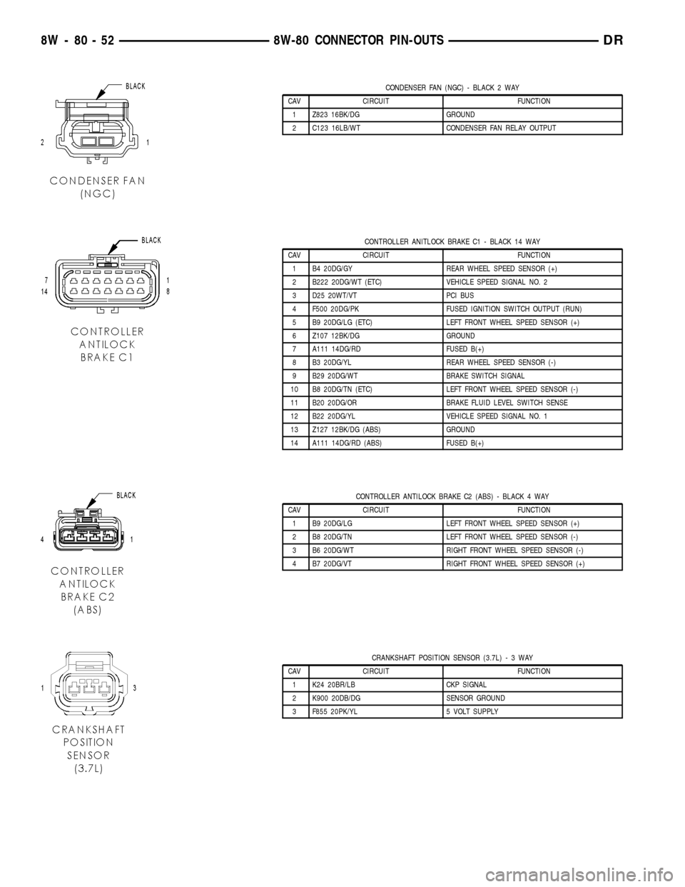
CONDENSER FAN (NGC) - BLACK 2 WAY
CAV CIRCUIT FUNCTION
1 Z823 16BK/DG GROUND
2 C123 16LB/WT CONDENSER FAN RELAY OUTPUT
CONTROLLER ANITLOCK BRAKE C1 - BLACK 14 WAY
CAV CIRCUIT FUNCTION
1 B4 20DG/GY REAR WHEEL SPEED SENSOR (+)
2 B222 20DG/WT (ETC) VEHICLE SPEED SIGNAL NO. 2
3 D25 20WT/VT PCI BUS
4 F500 20DG/PK FUSED IGNITION SWITCH OUTPUT (RUN)
5 B9 20DG/LG (ETC) LEFT FRONT WHEEL SPEED SENSOR (+)
6 Z107 12BK/DG GROUND
7 A111 14DG/RD FUSED B(+)
8 B3 20DG/YL REAR WHEEL SPEED SENSOR (-)
9 B29 20DG/WT BRAKE SWITCH SIGNAL
10 B8 20DG/TN (ETC) LEFT FRONT WHEEL SPEED SENSOR (-)
11 B20 20DG/OR BRAKE FLUID LEVEL SWITCH SENSE
12 B22 20DG/YL VEHICLE SPEED SIGNAL NO. 1
13 Z127 12BK/DG (ABS) GROUND
14 A111 14DG/RD (ABS) FUSED B(+)
CONTROLLER ANTILOCK BRAKE C2 (ABS) - BLACK 4 WAY
CAV CIRCUIT FUNCTION
1 B9 20DG/LG LEFT FRONT WHEEL SPEED SENSOR (+)
2 B8 20DG/TN LEFT FRONT WHEEL SPEED SENSOR (-)
3 B6 20DG/WT RIGHT FRONT WHEEL SPEED SENSOR (-)
4 B7 20DG/VT RIGHT FRONT WHEEL SPEED SENSOR (+)
CRANKSHAFT POSITION SENSOR (3.7L)-3WAY
CAV CIRCUIT FUNCTION
1 K24 20BR/LB CKP SIGNAL
2 K900 20DB/DG SENSOR GROUND
3 F855 20PK/YL 5 VOLT SUPPLY
8W - 80 - 52 8W-80 CONNECTOR PIN-OUTSDR
Page 1153 of 2627

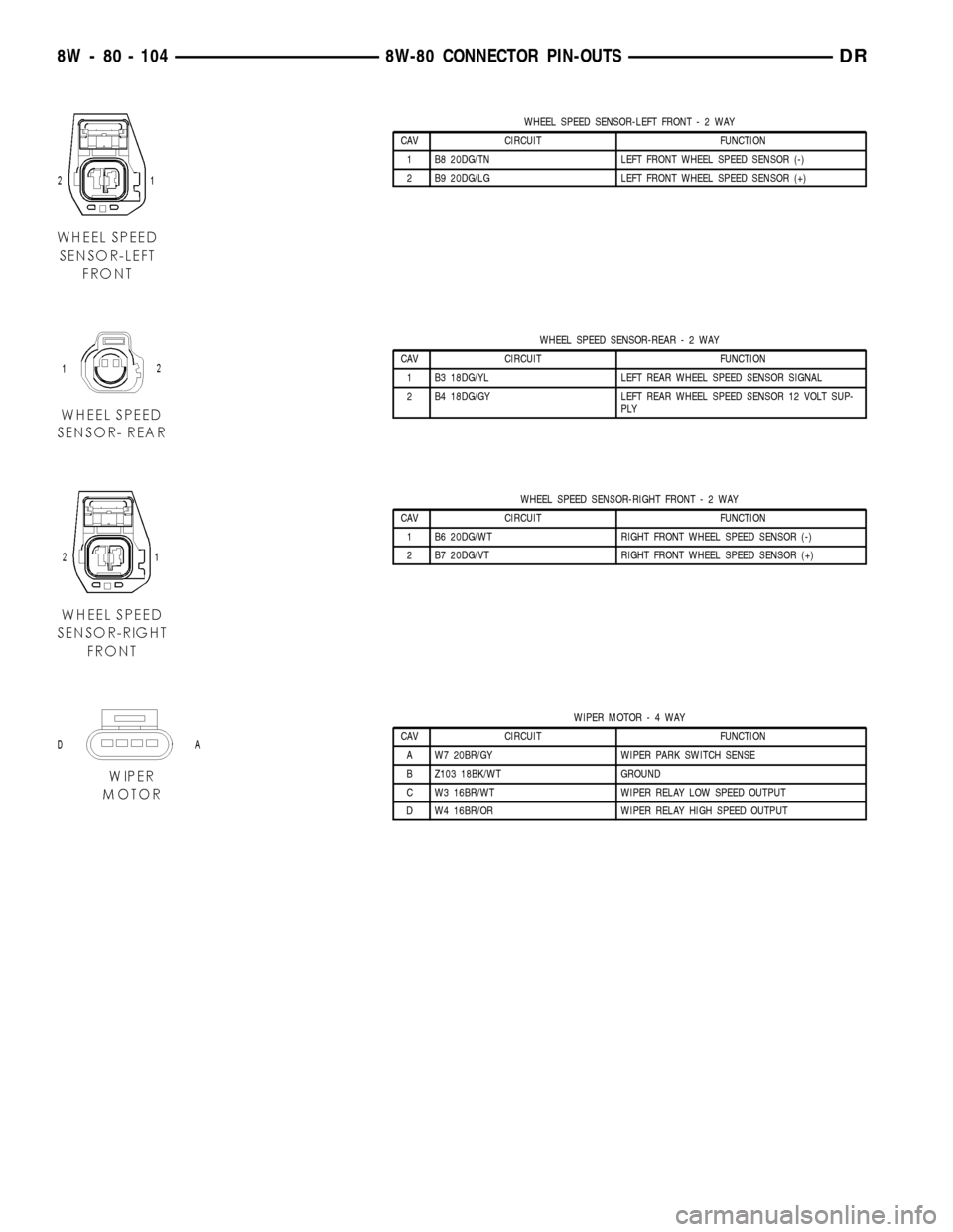
WHEEL SPEED SENSOR-LEFT FRONT-2WAY
CAV CIRCUIT FUNCTION
1 B8 20DG/TN LEFT FRONT WHEEL SPEED SENSOR (-)
2 B9 20DG/LG LEFT FRONT WHEEL SPEED SENSOR (+)
WHEEL SPEED SENSOR-REAR-2WAY
CAV CIRCUIT FUNCTION
1 B3 18DG/YL LEFT REAR WHEEL SPEED SENSOR SIGNAL
2 B4 18DG/GY LEFT REAR WHEEL SPEED SENSOR 12 VOLT SUP-
PLY
WHEEL SPEED SENSOR-RIGHT FRONT-2WAY
CAV CIRCUIT FUNCTION
1 B6 20DG/WT RIGHT FRONT WHEEL SPEED SENSOR (-)
2 B7 20DG/VT RIGHT FRONT WHEEL SPEED SENSOR (+)
WIPER MOTOR-4WAY
CAV CIRCUIT FUNCTION
A W7 20BR/GY WIPER PARK SWITCH SENSE
B Z103 18BK/WT GROUND
C W3 16BR/WT WIPER RELAY LOW SPEED OUTPUT
D W4 16BR/OR WIPER RELAY HIGH SPEED OUTPUT
8W - 80 - 104 8W-80 CONNECTOR PIN-OUTSDR
Page 1158 of 2627

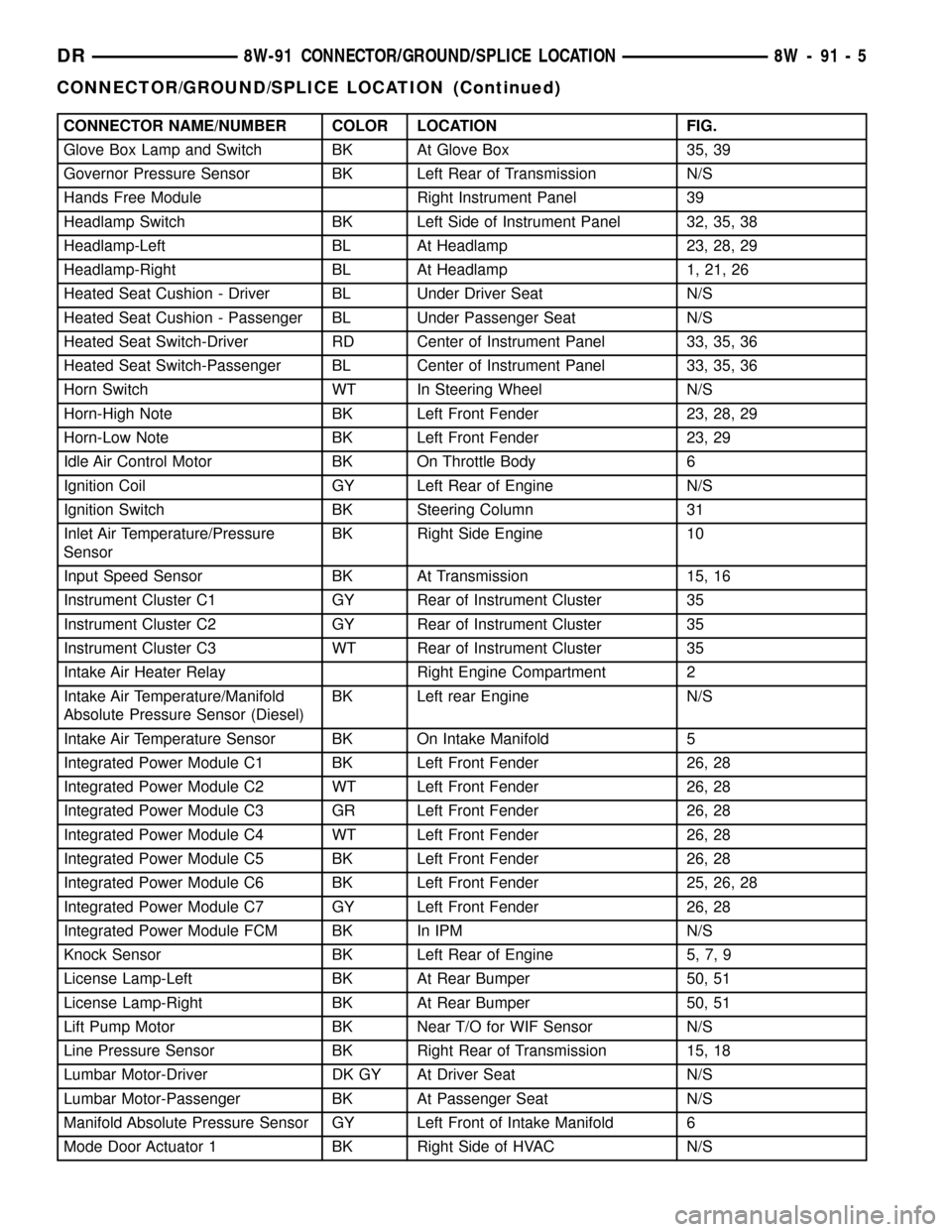
CONNECTOR NAME/NUMBER COLOR LOCATION FIG.
Glove Box Lamp and Switch BK At Glove Box 35, 39
Governor Pressure Sensor BK Left Rear of Transmission N/S
Hands Free Module Right Instrument Panel 39
Headlamp Switch BK Left Side of Instrument Panel 32, 35, 38
Headlamp-Left BL At Headlamp 23, 28, 29
Headlamp-Right BL At Headlamp 1, 21, 26
Heated Seat Cushion - Driver BL Under Driver Seat N/S
Heated Seat Cushion - Passenger BL Under Passenger Seat N/S
Heated Seat Switch-Driver RD Center of Instrument Panel 33, 35, 36
Heated Seat Switch-Passenger BL Center of Instrument Panel 33, 35, 36
Horn Switch WT In Steering Wheel N/S
Horn-High Note BK Left Front Fender 23, 28, 29
Horn-Low Note BK Left Front Fender 23, 29
Idle Air Control Motor BK On Throttle Body 6
Ignition Coil GY Left Rear of Engine N/S
Ignition Switch BK Steering Column 31
Inlet Air Temperature/Pressure
SensorBK Right Side Engine 10
Input Speed Sensor BK At Transmission 15, 16
Instrument Cluster C1 GY Rear of Instrument Cluster 35
Instrument Cluster C2 GY Rear of Instrument Cluster 35
Instrument Cluster C3 WT Rear of Instrument Cluster 35
Intake Air Heater Relay Right Engine Compartment 2
Intake Air Temperature/Manifold
Absolute Pressure Sensor (Diesel)BK Left rear Engine N/S
Intake Air Temperature Sensor BK On Intake Manifold 5
Integrated Power Module C1 BK Left Front Fender 26, 28
Integrated Power Module C2 WT Left Front Fender 26, 28
Integrated Power Module C3 GR Left Front Fender 26, 28
Integrated Power Module C4 WT Left Front Fender 26, 28
Integrated Power Module C5 BK Left Front Fender 26, 28
Integrated Power Module C6 BK Left Front Fender 25, 26, 28
Integrated Power Module C7 GY Left Front Fender 26, 28
Integrated Power Module FCM BK In IPM N/S
Knock Sensor BK Left Rear of Engine 5, 7, 9
License Lamp-Left BK At Rear Bumper 50, 51
License Lamp-Right BK At Rear Bumper 50, 51
Lift Pump Motor BK Near T/O for WIF Sensor N/S
Line Pressure Sensor BK Right Rear of Transmission 15, 18
Lumbar Motor-Driver DK GY At Driver Seat N/S
Lumbar Motor-Passenger BK At Passenger Seat N/S
Manifold Absolute Pressure Sensor GY Left Front of Intake Manifold 6
Mode Door Actuator 1 BK Right Side of HVAC N/S
DR8W-91 CONNECTOR/GROUND/SPLICE LOCATION 8W - 91 - 5
CONNECTOR/GROUND/SPLICE LOCATION (Continued)
Page 1161 of 2627

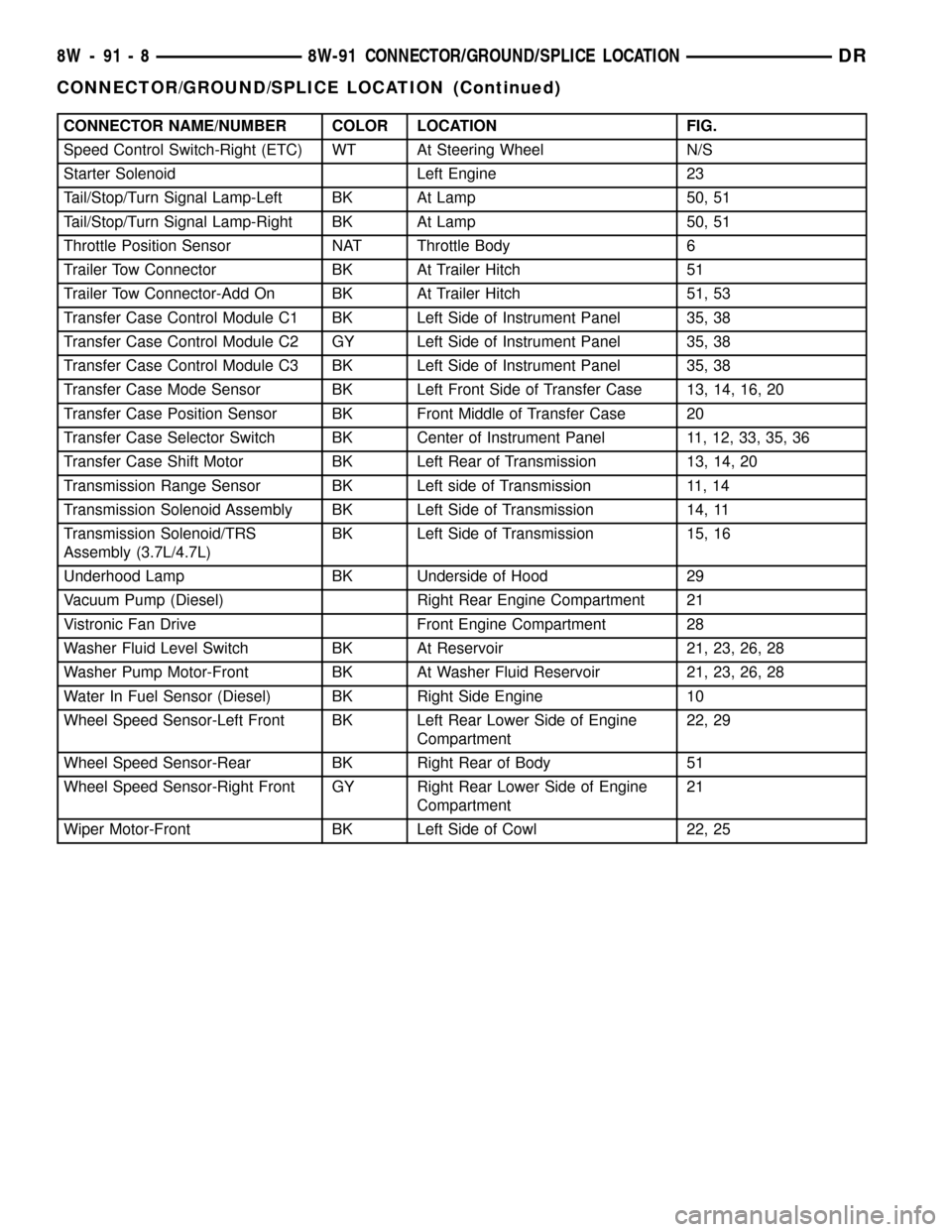
CONNECTOR NAME/NUMBER COLOR LOCATION FIG.
Speed Control Switch-Right (ETC) WT At Steering Wheel N/S
Starter Solenoid Left Engine 23
Tail/Stop/Turn Signal Lamp-Left BK At Lamp 50, 51
Tail/Stop/Turn Signal Lamp-Right BK At Lamp 50, 51
Throttle Position Sensor NAT Throttle Body 6
Trailer Tow Connector BK At Trailer Hitch 51
Trailer Tow Connector-Add On BK At Trailer Hitch 51, 53
Transfer Case Control Module C1 BK Left Side of Instrument Panel 35, 38
Transfer Case Control Module C2 GY Left Side of Instrument Panel 35, 38
Transfer Case Control Module C3 BK Left Side of Instrument Panel 35, 38
Transfer Case Mode Sensor BK Left Front Side of Transfer Case 13, 14, 16, 20
Transfer Case Position Sensor BK Front Middle of Transfer Case 20
Transfer Case Selector Switch BK Center of Instrument Panel 11, 12, 33, 35, 36
Transfer Case Shift Motor BK Left Rear of Transmission 13, 14, 20
Transmission Range Sensor BK Left side of Transmission 11, 14
Transmission Solenoid Assembly BK Left Side of Transmission 14, 11
Transmission Solenoid/TRS
Assembly (3.7L/4.7L)BK Left Side of Transmission 15, 16
Underhood Lamp BK Underside of Hood 29
Vacuum Pump (Diesel) Right Rear Engine Compartment 21
Vistronic Fan Drive Front Engine Compartment 28
Washer Fluid Level Switch BK At Reservoir 21, 23, 26, 28
Washer Pump Motor-Front BK At Washer Fluid Reservoir 21, 23, 26, 28
Water In Fuel Sensor (Diesel) BK Right Side Engine 10
Wheel Speed Sensor-Left Front BK Left Rear Lower Side of Engine
Compartment22, 29
Wheel Speed Sensor-Rear BK Right Rear of Body 51
Wheel Speed Sensor-Right Front GY Right Rear Lower Side of Engine
Compartment21
Wiper Motor-Front BK Left Side of Cowl 22, 25
8W - 91 - 8 8W-91 CONNECTOR/GROUND/SPLICE LOCATIONDR
CONNECTOR/GROUND/SPLICE LOCATION (Continued)