bolt pattern DODGE RAM 1500 1998 2.G Owner's Manual
[x] Cancel search | Manufacturer: DODGE, Model Year: 1998, Model line: RAM 1500, Model: DODGE RAM 1500 1998 2.GPages: 2627
Page 224 of 2627
Condition Possible Causes Correction
Axle Noise 1. Insufficient lubricant. 1. Fill differential with the correct fluid
type and quantity.
2. Improper ring gear and pinion
adjustment.2. Check ring gear and pinion contact
pattern. Adjust backlash or pinion
depth.
3. Unmatched ring gear and pinion. 3. Replace gears with a matched ring
gear and pinion.
4. Worn teeth on ring gear and/or
pinion.4. Replace ring gear and pinion.
5. Loose pinion bearings. 5. Adjust pinion bearing pre-load.
6. Loose differential bearings. 6. Adjust differential bearing pre-load.
7. Mis-aligned or sprung ring gear. 7. Measure ring gear run-out. Replace
components as necessary.
8. Loose differential bearing cap
bolts.8. Inspect differential components and
replace as necessary. Ensure that the
bearing caps are torqued tot he
proper specification.
9. Housing not machined properly. 9. Replace housing.
REMOVAL
(1) Raise and support the vehicle.
(2) Position a lifting device under axle and secure
lift to the axle.
(3) Remove wheels and tires assemblies.
(4) Remove all brake components.
(5) Mark propeller shaft and companion flange for
installation alignment reference.
(6) Remove propeller shaft.
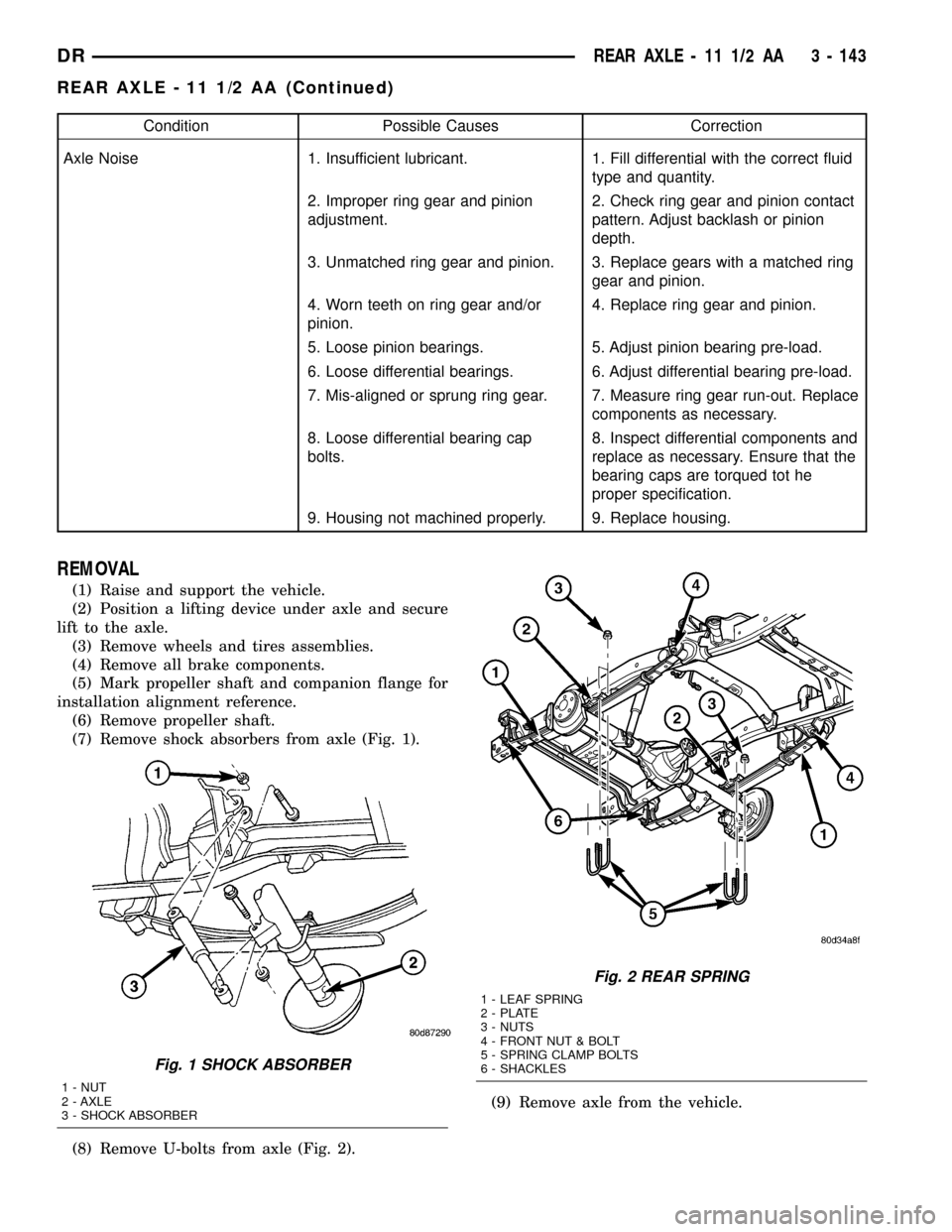
(7) Remove shock absorbers from axle (Fig. 1).
(8) Remove U-bolts from axle (Fig. 2).(9) Remove axle from the vehicle.
Fig. 1 SHOCK ABSORBER
1 - NUT
2 - AXLE
3 - SHOCK ABSORBER
Fig. 2 REAR SPRING
1 - LEAF SPRING
2 - PLATE
3 - NUTS
4 - FRONT NUT & BOLT
5 - SPRING CLAMP BOLTS
6 - SHACKLES
DRREAR AXLE - 11 1/2 AA 3 - 143
REAR AXLE - 11 1/2 AA (Continued)
Page 226 of 2627
DIFFERENTIAL CASE BEARING PRELOAD AND
GEAR BACKLASH
Backlash is adjusted by moving the adjusters in
and out or both. By moving the adjusters the case/
ring gear will move closer or further away from the
pinion. In most cases this adjustment can be used to
achieve the correct gear tooth pattern and set the
case bearing preload.
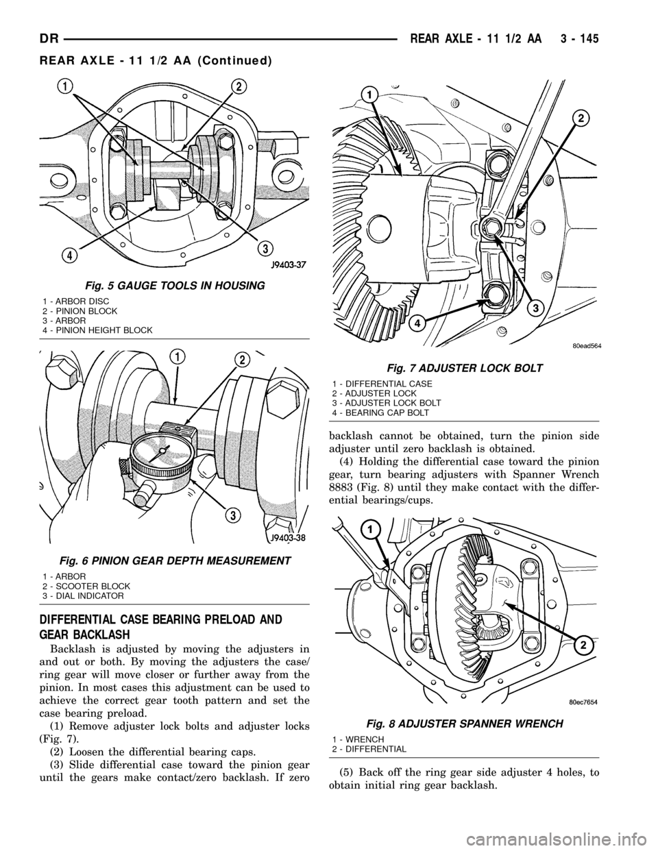
(1) Remove adjuster lock bolts and adjuster locks
(Fig. 7).
(2) Loosen the differential bearing caps.
(3) Slide differential case toward the pinion gear
until the gears make contact/zero backlash. If zerobacklash cannot be obtained, turn the pinion side
adjuster until zero backlash is obtained.
(4) Holding the differential case toward the pinion
gear, turn bearing adjusters with Spanner Wrench
8883 (Fig. 8) until they make contact with the differ-
ential bearings/cups.
(5) Back off the ring gear side adjuster 4 holes, to
obtain initial ring gear backlash.
Fig. 5 GAUGE TOOLS IN HOUSING
1 - ARBOR DISC
2 - PINION BLOCK
3 - ARBOR
4 - PINION HEIGHT BLOCK
Fig. 6 PINION GEAR DEPTH MEASUREMENT
1 - ARBOR
2 - SCOOTER BLOCK
3 - DIAL INDICATOR
Fig. 7 ADJUSTER LOCK BOLT
1 - DIFFERENTIAL CASE
2 - ADJUSTER LOCK
3 - ADJUSTER LOCK BOLT
4 - BEARING CAP BOLT
Fig. 8 ADJUSTER SPANNER WRENCH
1 - WRENCH
2 - DIFFERENTIAL
DRREAR AXLE - 11 1/2 AA 3 - 145
REAR AXLE - 11 1/2 AA (Continued)
Page 227 of 2627
(6) Install ring gear side adjuster lock and bolt. Do
not tighten adjuster lock bolt at this time.
(7) Tighten pinion gear side adjuster firmly
against the differential case bearing cup.
(8) Rotate the pinion several times to seat the def-
erential bearings.
(9) Loosen pinion gear side adjuster until it is no
longer in contact with the bearing cup, then tighten
it until it makes contact.
(10) Tighten pinion gear side adjuster an addi-
tional:
²New Bearings:6 Adjuster Holes
²Original Bearings:4 Adjuster Holes
(11) Install pinion gear side adjuster lock and bolt.
Do not tighten adjuster lock bolt at this time.
(12) Tighten bearing cap bolts to 115 N´m (85 ft.
lbs.).
(13) Tighten adjuster lock bolts to 33 N´m (24 ft.
lbs.).
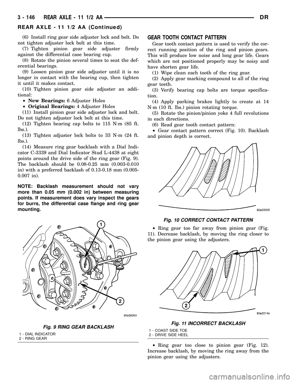
(14) Measure ring gear backlash with a Dial Indi-
cator C-3339 and Dial Indicator Stud L-4438 at eight
points around the drive side of the ring gear (Fig. 9).
The backlash should be 0.08-0.25 mm (0.003-0.010
in) with a preferred backlash of 0.13-0.18 mm (0.005-
0.007 in).
NOTE: Backlash measurement should not vary
more than 0.05 mm (0.002 in) between measuring
points. If measurement does vary inspect the gears
for burrs, the differential case flange and ring gear
mounting.GEAR TOOTH CONTACT PATTERN
Gear tooth contact pattern is used to verify the cor-
rect running position of the ring and pinion gears.
This will produce low noise and long gear life. Gears
which are not positioned properly may be noisy and
have shorten gear life.
(1) Wipe clean each tooth of the ring gear.
(2) Apply gear marking compound to all of the ring
gear teeth.
(3) Verify bearing cap bolts are torque specifica-
tion.
(4) Apply parking brakes lightly to create at 14
N´m (10 ft. lbs.) pinion rotating torque.
(5) Rotate the pinion/pinion yoke 4 full revolutions
in each directions.
(6) Read gear tooth contact pattern:
²Gear contact pattern correct (Fig. 10). Backlash
and pinion depth is correct.
²Ring gear too far away from pinion gear (Fig.
11). Decrease backlash, by moving the ring closer to
the pinion gear using the adjusters.
²Ring gear too close to pinion gear (Fig. 12).
Increase backlash, by moving the ring away from the
pinion gear using the adjusters.
Fig. 9 RING GEAR BACKLASH
1 - DIAL INDICATOR
2 - RING GEAR
Fig. 10 CORRECT CONTACT PATTERN
Fig. 11 INCORRECT BACKLASH
1 - COAST SIDE TOE
2 - DRIVE SIDE HEEL
3 - 146 REAR AXLE - 11 1/2 AADR
REAR AXLE - 11 1/2 AA (Continued)
Page 239 of 2627
(5) Slide differential case toward the pinion gear
until the gears make contact/zero backlash. If zero
backlash cannot be obtained, turn the pinion side
adjuster until zero backlash is obtained.
(6) Holding the differential case toward the pinion
gear, turn bearing adjusters with Spanner Wrench
8883 until they make contact with the differential
bearings/cups.
(7) Back off the ring gear side adjuster 4 holes, to
obtain initial ring gear backlash.
(8) Install ring gear side adjuster lock and bolt. Do
not tighten adjuster lock bolt at this time.
(9) Tighten pinion gear side adjuster firmly
against the differential case bearing cup.
(10) Rotate the pinion several times to seat the dif-
ferential bearings.
(11) Loosen pinion gear side adjuster until it is no
longer in contact with the bearing cup.
(12) Tighten pinion gear side adjuster until it just
makes contact with the bearing cup.
(13) Tighten pinion gear side adjuster an addi-
tional:
²New Bearings6 Adjuster Holes
²Original Bearings4 Adjuster Holes
(14) Install pinion gear side adjuster lock and bolt.
Do not tighten adjuster lock bolt at this time.
(15) Tighten bearing cap bolts to 281 N´m (207 ft.
lbs.).
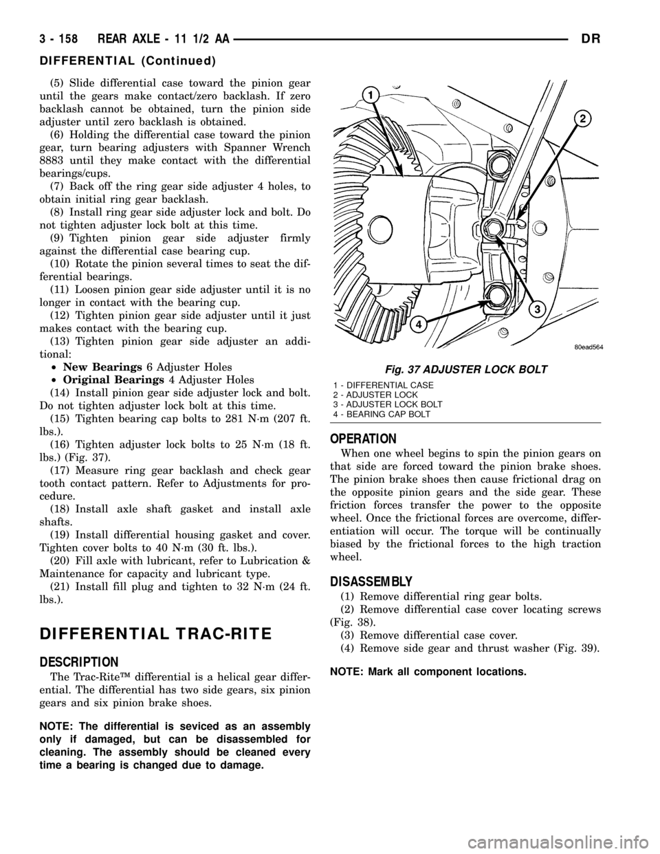
(16) Tighten adjuster lock bolts to 25 N´m (18 ft.
lbs.) (Fig. 37).
(17) Measure ring gear backlash and check gear
tooth contact pattern. Refer to Adjustments for pro-
cedure.
(18) Install axle shaft gasket and install axle
shafts.
(19) Install differential housing gasket and cover.
Tighten cover bolts to 40 N´m (30 ft. lbs.).
(20) Fill axle with lubricant, refer to Lubrication &
Maintenance for capacity and lubricant type.
(21) Install fill plug and tighten to 32 N´m (24 ft.
lbs.).
DIFFERENTIAL TRAC-RITE
DESCRIPTION
The Trac-RiteŸ differential is a helical gear differ-
ential. The differential has two side gears, six pinion
gears and six pinion brake shoes.
NOTE: The differential is seviced as an assembly
only if damaged, but can be disassembled for
cleaning. The assembly should be cleaned every
time a bearing is changed due to damage.
OPERATION
When one wheel begins to spin the pinion gears on
that side are forced toward the pinion brake shoes.
The pinion brake shoes then cause frictional drag on
the opposite pinion gears and the side gear. These
friction forces transfer the power to the opposite
wheel. Once the frictional forces are overcome, differ-
entiation will occur. The torque will be continually
biased by the frictional forces to the high traction
wheel.
DISASSEMBLY
(1) Remove differential ring gear bolts.
(2) Remove differential case cover locating screws
(Fig. 38).
(3) Remove differential case cover.
(4) Remove side gear and thrust washer (Fig. 39).
NOTE: Mark all component locations.
Fig. 37 ADJUSTER LOCK BOLT
1 - DIFFERENTIAL CASE
2 - ADJUSTER LOCK
3 - ADJUSTER LOCK BOLT
4 - BEARING CAP BOLT
3 - 158 REAR AXLE - 11 1/2 AADR
DIFFERENTIAL (Continued)
Page 248 of 2627

(21) Install differential in housing and verify gear
backlash and gear contact pattern.
(22) Measure final rotating torque with an inch
pound torque wrench. The final pinion rotating
torque plus differential case bearing preload is:
²New Bearings:3.4-5.6 N´m (30-50 in. lbs.)
²Original Bearings:2.8-5.1 N´m (25-45 in. lbs.)
(23) Install axle shafts.(24) Install the propeller shaft with the reference
marks aligned.
(25) Install differential cover with gasket and
tighten bolts to 40 N´m (30 ft. lbs.).
(26) Fill differential with fluid and tighten fill plug
to 32 N´m (24 ft. lbs.).
DRREAR AXLE - 11 1/2 AA 3 - 167
PINION GEAR/RING GEAR/TONE RING (Continued)
Page 306 of 2627
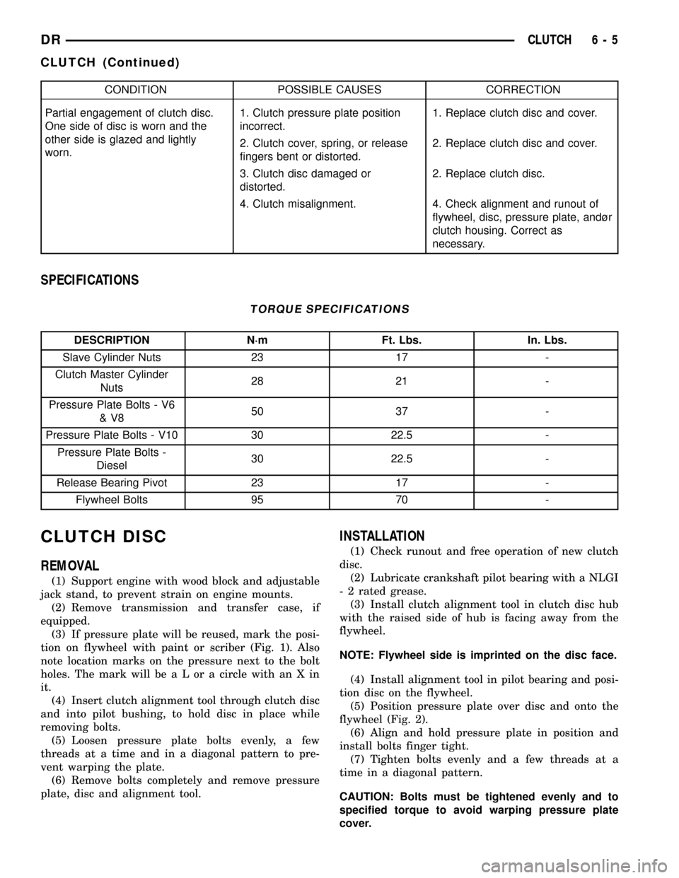
CONDITION POSSIBLE CAUSES CORRECTION
Partial engagement of clutch disc.
One side of disc is worn and the
other side is glazed and lightly
worn.1. Clutch pressure plate position
incorrect.1. Replace clutch disc and cover.
2. Clutch cover, spring, or release
fingers bent or distorted.2. Replace clutch disc and cover.
3. Clutch disc damaged or
distorted.2. Replace clutch disc.
4. Clutch misalignment. 4. Check alignment and runout of
flywheel, disc, pressure plate, andùr
clutch housing. Correct as
necessary.
SPECIFICATIONS
TORQUE SPECIFICATIONS
DESCRIPTION N´m Ft. Lbs. In. Lbs.
Slave Cylinder Nuts 23 17 -
Clutch Master Cylinder
Nuts28 21 -
Pressure Plate Bolts - V6
&V850 37 -
Pressure Plate Bolts - V10 30 22.5 -
Pressure Plate Bolts -
Diesel30 22.5 -
Release Bearing Pivot 23 17 -
Flywheel Bolts 95 70 -
CLUTCH DISC
REMOVAL
(1) Support engine with wood block and adjustable
jack stand, to prevent strain on engine mounts.
(2) Remove transmission and transfer case, if
equipped.
(3) If pressure plate will be reused, mark the posi-
tion on flywheel with paint or scriber (Fig. 1). Also
note location marks on the pressure next to the bolt
holes. The mark will be a L or a circle with an X in
it.
(4) Insert clutch alignment tool through clutch disc
and into pilot bushing, to hold disc in place while
removing bolts.
(5) Loosen pressure plate bolts evenly, a few
threads at a time and in a diagonal pattern to pre-
vent warping the plate.
(6) Remove bolts completely and remove pressure
plate, disc and alignment tool.
INSTALLATION
(1) Check runout and free operation of new clutch
disc.
(2) Lubricate crankshaft pilot bearing with a NLGI
- 2 rated grease.
(3) Install clutch alignment tool in clutch disc hub
with the raised side of hub is facing away from the
flywheel.
NOTE: Flywheel side is imprinted on the disc face.
(4) Install alignment tool in pilot bearing and posi-
tion disc on the flywheel.
(5) Position pressure plate over disc and onto the
flywheel (Fig. 2).
(6) Align and hold pressure plate in position and
install bolts finger tight.
(7) Tighten bolts evenly and a few threads at a
time in a diagonal pattern.
CAUTION: Bolts must be tightened evenly and to
specified torque to avoid warping pressure plate
cover.
DRCLUTCH 6 - 5
CLUTCH (Continued)
Page 339 of 2627
INSTALLATION
(1) Install tensioner assembly to water inlet
bracket. A dowel is located on back of tensioner. Align
this dowel to hole in tensioner mounting bracket.
Tighten bolt to 43 N´m (32 ft. lbs.) torque.
(2) Install drive belt (Refer to 7 - COOLING/AC-
CESSORY DRIVE/DRIVE BELTS - INSTALLA-
TION).
DRIVE BELT - 3.7L / 4.7L
DIAGNOSIS AND TESTING - ACCESSORY
DRIVE BELT
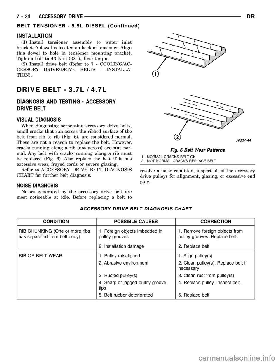
VISUAL DIAGNOSIS
When diagnosing serpentine accessory drive belts,
small cracks that run across the ribbed surface of the
belt from rib to rib (Fig. 6), are considered normal.
These are not a reason to replace the belt. However,
cracks running along a rib (not across) arenotnor-
mal. Any belt with cracks running along a rib must
be replaced (Fig. 6). Also replace the belt if it has
excessive wear, frayed cords or severe glazing.
Refer to ACCESSORY DRIVE BELT DIAGNOSIS
CHART for further belt diagnosis.
NOISE DIAGNOSIS
Noises generated by the accessory drive belt are
most noticeable at idle. Before replacing a belt toresolve a noise condition, inspect all of the accessory
drive pulleys for alignment, glazing, or excessive end
play.
ACCESSORY DRIVE BELT DIAGNOSIS CHART
CONDITION POSSIBLE CAUSES CORRECTION
RIB CHUNKING (One or more ribs
has separated from belt body)1. Foreign objects imbedded in
pulley grooves.1. Remove foreign objects from
pulley grooves. Replace belt.
2. Installation damage 2. Replace belt
RIB OR BELT WEAR 1. Pulley misaligned 1. Align pulley(s)
2. Abrasive environment 2. Clean pulley(s). Replace belt if
necessary
3. Rusted pulley(s) 3. Clean rust from pulley(s)
4. Sharp or jagged pulley groove
tips4. Replace pulley. Inspect belt.
5. Belt rubber deteriorated 5. Replace belt
Fig. 6 Belt Wear Patterns
1 - NORMAL CRACKS BELT OK
2 - NOT NORMAL CRACKS REPLACE BELT
7 - 24 ACCESSORY DRIVEDR
BELT TENSIONER - 5.9L DIESEL (Continued)
Page 466 of 2627
5.7L
(1) Connect solenoid wire to starter motor (snaps
on).
(2) Position battery cable to solenoid stud. Install
and tighten battery cable eyelet nut. Refer to Torque
Specifications. Do not allow starter motor to hang
from wire harness.
(3) Position starter motor to engine.
(4) If equipped with automatic transmission, slide
cooler tube bracket into position.
(5) Install and tighten both mounting bolts. Refer
to Torque Specifications.
(6) Lower vehicle.
(7) Connect negative battery cable.
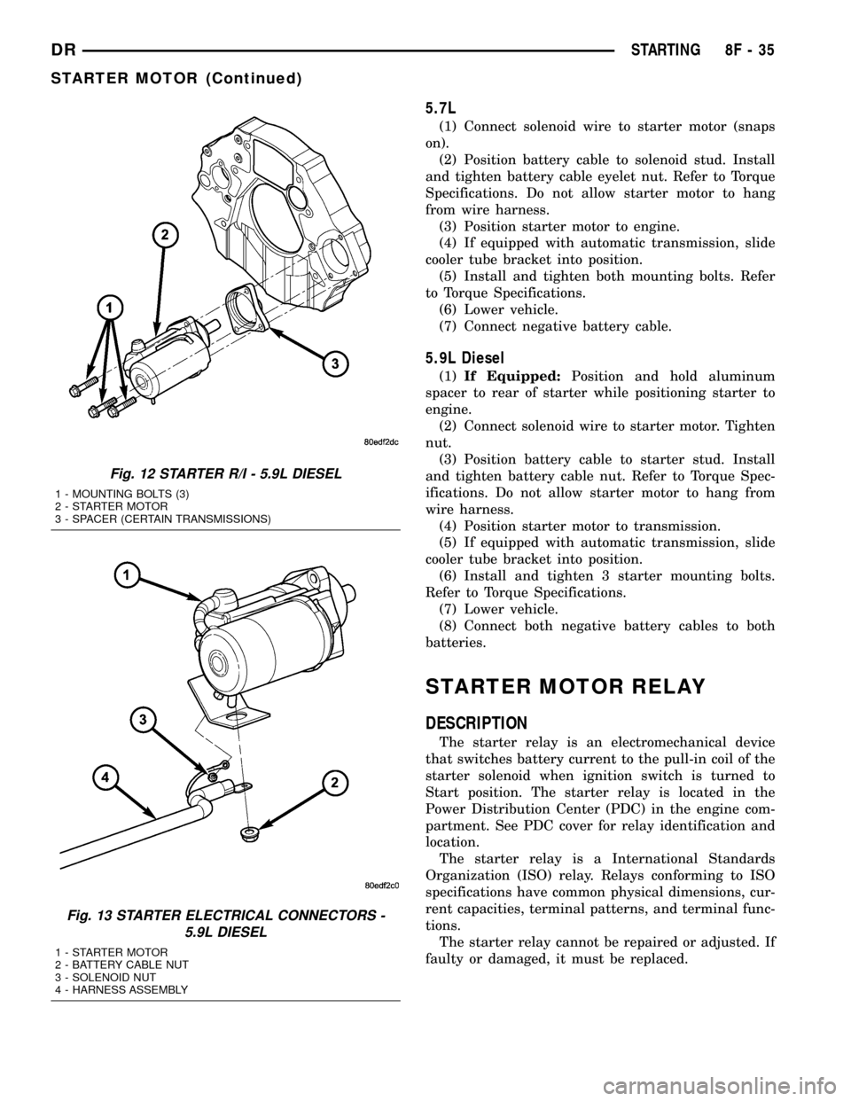
5.9L Diesel
(1)If Equipped:Position and hold aluminum
spacer to rear of starter while positioning starter to
engine.
(2) Connect solenoid wire to starter motor. Tighten
nut.
(3) Position battery cable to starter stud. Install
and tighten battery cable nut. Refer to Torque Spec-
ifications. Do not allow starter motor to hang from
wire harness.
(4) Position starter motor to transmission.
(5) If equipped with automatic transmission, slide
cooler tube bracket into position.
(6) Install and tighten 3 starter mounting bolts.
Refer to Torque Specifications.
(7) Lower vehicle.
(8) Connect both negative battery cables to both
batteries.
STARTER MOTOR RELAY
DESCRIPTION
The starter relay is an electromechanical device
that switches battery current to the pull-in coil of the
starter solenoid when ignition switch is turned to
Start position. The starter relay is located in the
Power Distribution Center (PDC) in the engine com-
partment. See PDC cover for relay identification and
location.
The starter relay is a International Standards
Organization (ISO) relay. Relays conforming to ISO
specifications have common physical dimensions, cur-
rent capacities, terminal patterns, and terminal func-
tions.
The starter relay cannot be repaired or adjusted. If
faulty or damaged, it must be replaced.
Fig. 12 STARTER R/I - 5.9L DIESEL
1 - MOUNTING BOLTS (3)
2 - STARTER MOTOR
3 - SPACER (CERTAIN TRANSMISSIONS)
Fig. 13 STARTER ELECTRICAL CONNECTORS -
5.9L DIESEL
1 - STARTER MOTOR
2 - BATTERY CABLE NUT
3 - SOLENOID NUT
4 - HARNESS ASSEMBLY
DRSTARTING 8F - 35
STARTER MOTOR (Continued)
Page 494 of 2627
CAMSHAFT POSITION SENSOR
DESCRIPTION
3.7L V-6
The Camshaft Position Sensor (CMP) on the 3.7L
6-cylinder engine is bolted to the right-front side of
the right cylinder head.
4.7L V-8
The Camshaft Position Sensor (CMP) on the 4.7L
V-8 engine is bolted to the right-front side of the
right cylinder head.
5.7L V-8
The Camshaft Position Sensor (CMP) on the 5.7L
V-8 engine is located below the generator on the tim-
ing chain / case cover on the right/front side of
engine.
5.9L Diesel
The Camshaft Position Sensor (CMP) on the 5.9L
diesel engine is located below the fuel injection
pump. It is bolted to the back of the timing gear
cover.
OPERATION
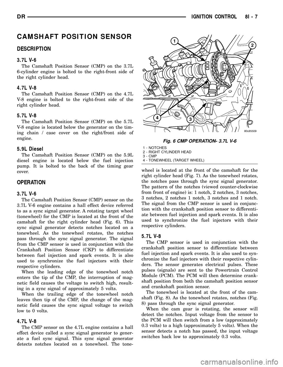
3.7L V-6
The Camshaft Position Sensor (CMP) sensor on the
3.7L V-6 engine contains a hall effect device referred
to as a sync signal generator. A rotating target wheel
(tonewheel) for the CMP is located at the front of the
camshaft for the right cylinder head (Fig. 6). This
sync signal generator detects notches located on a
tonewheel. As the tonewheel rotates, the notches
pass through the sync signal generator. The signal
from the CMP sensor is used in conjunction with the
Crankshaft Position Sensor (CKP) to differentiate
between fuel injection and spark events. It is also
used to synchronize the fuel injectors with their
respective cylinders.
When the leading edge of the tonewheel notch
enters the tip of the CMP, the interruption of mag-
netic field causes the voltage to switch high, result-
ing in a sync signal of approximately 5 volts.
When the trailing edge of the tonewheel notch
leaves then tip of the CMP, the change of the mag-
netic field causes the sync signal voltage to switch
low to 0 volts.
4.7L V-8
The CMP sensor on the 4.7L engine contains a hall
effect device called a sync signal generator to gener-
ate a fuel sync signal. This sync signal generator
detects notches located on a tonewheel. The tone-wheel is located at the front of the camshaft for the
right cylinder head (Fig. 7). As the tonewheel rotates,
the notches pass through the sync signal generator.
The pattern of the notches (viewed counter-clockwise
from front of engine) is: 1 notch, 2 notches, 3 notches,
3 notches, 2 notches 1 notch, 3 notches and 1 notch.
The signal from the CMP sensor is used in conjunc-
tion with the crankshaft position sensor to differenti-
ate between fuel injection and spark events. It is also
used to synchronize the fuel injectors with their
respective cylinders.
5.7L V-8
The CMP sensor is used in conjunction with the
crankshaft position sensor to differentiate between
fuel injection and spark events. It is also used to syn-
chronize the fuel injectors with their respective cylin-
ders. The sensor generates electrical pulses. These
pulses (signals) are sent to the Powertrain Control
Module (PCM). The PCM will then determine crank-
shaft position from both the camshaft position sensor
and crankshaft position sensor.
The tonewheel is located at the front of the cam-
shaft (Fig. 8). As the tonewheel rotates, notches (Fig.
8) pass through the sync signal generator.
When the cam gear is rotating, the sensor will
detect the notches. Input voltage from the sensor to
the PCM will then switch from a low (approximately
0.3 volts) to a high (approximately 5 volts). When the
sensor detects a notch has passed, the input voltage
switches back low to approximately 0.3 volts.
Fig. 6 CMP OPERATION- 3.7L V-6
1 - NOTCHES
2 - RIGHT CYLINDER HEAD
3 - CMP
4 - TONEWHEEL (TARGET WHEEL)
DRIGNITION CONTROL 8I - 7
Page 571 of 2627
(3) Install the bolts attaching headlamp unit to the
fender (Fig. 11).
(4) Align the seal and install the push pins.
(5) Connect the battery negative cable.
ADJUSTMENTS
Headlamps can be aligned using the screen method
provided in this section.
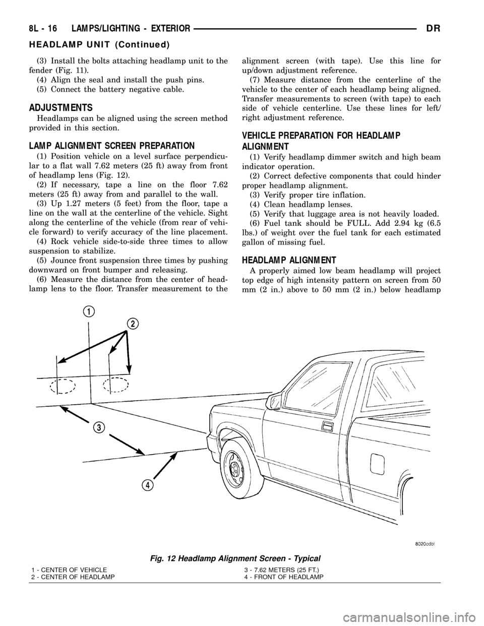
LAMP ALIGNMENT SCREEN PREPARATION
(1) Position vehicle on a level surface perpendicu-
lar to a flat wall 7.62 meters (25 ft) away from front
of headlamp lens (Fig. 12).
(2) If necessary, tape a line on the floor 7.62
meters (25 ft) away from and parallel to the wall.
(3) Up 1.27 meters (5 feet) from the floor, tape a
line on the wall at the centerline of the vehicle. Sight
along the centerline of the vehicle (from rear of vehi-
cle forward) to verify accuracy of the line placement.
(4) Rock vehicle side-to-side three times to allow
suspension to stabilize.
(5) Jounce front suspension three times by pushing
downward on front bumper and releasing.
(6) Measure the distance from the center of head-
lamp lens to the floor. Transfer measurement to thealignment screen (with tape). Use this line for
up/down adjustment reference.
(7) Measure distance from the centerline of the
vehicle to the center of each headlamp being aligned.
Transfer measurements to screen (with tape) to each
side of vehicle centerline. Use these lines for left/
right adjustment reference.
VEHICLE PREPARATION FOR HEADLAMP
ALIGNMENT
(1) Verify headlamp dimmer switch and high beam
indicator operation.
(2) Correct defective components that could hinder
proper headlamp alignment.
(3) Verify proper tire inflation.
(4) Clean headlamp lenses.
(5) Verify that luggage area is not heavily loaded.
(6) Fuel tank should be FULL. Add 2.94 kg (6.5
lbs.) of weight over the fuel tank for each estimated
gallon of missing fuel.
HEADLAMP ALIGNMENT
A properly aimed low beam headlamp will project
top edge of high intensity pattern on screen from 50
mm (2 in.) above to 50 mm (2 in.) below headlamp
Fig. 12 Headlamp Alignment Screen - Typical
1 - CENTER OF VEHICLE
2 - CENTER OF HEADLAMP3 - 7.62 METERS (25 FT.)
4 - FRONT OF HEADLAMP
8L - 16 LAMPS/LIGHTING - EXTERIORDR
HEADLAMP UNIT (Continued)