manual transmission DODGE RAM 1500 1998 2.G Owner's Guide
[x] Cancel search | Manufacturer: DODGE, Model Year: 1998, Model line: RAM 1500, Model: DODGE RAM 1500 1998 2.GPages: 2627
Page 684 of 2627

(5) Verify operation of one-way check valve and
check it for leaks.
(a) Locate one-way check valve. The valve is
located in vacuum line between vacuum reservoir
and engine vacuum source. Disconnect vacuum
hoses (lines) at each end of valve.
(b) Connect a hand-operated vacuum pump to
reservoir end of check valve. Apply vacuum. Vac-
uum should not bleed off. If vacuum is being lost,
replace one-way check valve.
(c) Connect a hand-operated vacuum pump to
vacuum source end of check valve. Apply vacuum.
Vacuum should flow through valve. If vacuum is
not flowing, replace one-way check valve. Seal the
fitting at opposite end of valve with a finger and
apply vacuum. If vacuum will not hold, diaphragm
within check valve has ruptured. Replace valve.
5.7 Gas
Vacuum is not used for any part of the speed con-
trol system if equipped with a 5.7L V-8 engine.
5.9L Diesel Engine With Manual Trans.
Vacuum is not used for any part of the speed con-
trol system if equipped with a diesel engine and a
manual transmission.
5.9L Diesel Engines With Automatic Trans.
If equipped with a diesel powered engine and an
automatic transmission, an electric vacuum pump
and vacuum lines are used to supply vacuum to the
speed control servo. A vacuum reservoir is not used.
DIAGNOSIS AND TESTING - ROAD TEST
Perform a vehicle road test to verify reports of
speed control system malfunction. The road test
should include attention to the speedometer. Speed-ometer operation should be smooth and without flut-
ter at all speeds.
Flutter in the speedometer indicates a problem
which might cause surging in the speed control sys-
tem. The cause of any speedometer problems should
be corrected before proceeding. Refer to Instrument
Cluster for speedometer diagnosis.
If a road test verifies a system problem and the
speedometer operates properly, check for:
²A Diagnostic Trouble Code (DTC). If a DTC
exists, conduct tests per the Powertrain Diagnostic
Procedures service manual.
²A misadjusted brake (stop) lamp switch. This
could also cause an intermittent problem.
²Loose, damaged or corroded electrical connec-
tions at the servo (if used). Corrosion should be
removed from electrical terminals and a light coating
of Mopar MultiPurpose Grease, or equivalent,
applied.
²Leaking vacuum reservoir (if used).
²Loose or leaking vacuum hoses or connections (if
used).
²Defective one-way vacuum check valve (if used).
²Secure attachment of both ends of the speed con-
trol servo cable (if used).
²Smooth operation of throttle linkage (if used)
and throttle body air valve.
²Failed speed control servo (if used). Do the servo
vacuum test.
CAUTION: When test probing for voltage or conti-
nuity at electrical connectors, care must be taken
not to damage connector, terminals or seals. If
these components are damaged, intermittent or
complete system failure may occur.
SPECIFICATIONS
TORQUE - SPEED CONTROL
DESCRIPTION N-m Ft. Lbs. In. Lbs.
Servo Mounting Bracket-
to-Servo Nuts7-60
Servo Mounting Bracket-
to-Battery Tray Screws4-30
Speed Control Switch
Mounting Screws1.7 - 15
Vacuum Reservoir
Mounting Nuts3-20
DRSPEED CONTROL 8P - 3
SPEED CONTROL (Continued)
Page 685 of 2627

CABLE
DESCRIPTION
The speed control servo cable is connected between
the speed control vacuum servo diaphragm and the
throttle body control linkage. This cable is used with
3.7L/4.7L gas powered engines only. It is also used if
equipped with a 5.9L diesel engine equipped with an
automatic transmission.
A speed control servo cableis not usedif equipped
with either a 5.9L diesel engine equipped with a
manual transmission, or any 5.7L engine/transmis-
sion combinations.
OPERATION
This cable causes the throttle control linkage to
open or close the throttle valve in response to move-
ment of the vacuum servo diaphragm.
REMOVAL
3.7L / 4.7L GAS
(1) Disconnect negative battery cable at battery.
(2) Remove air intake tube at top of throttle body.
The accelerator cable must be partially removed to
gain access to speed control cable.
(3) Hold throttle in wide open position. While held
in this position, slide throttle cable pin (Fig. 1) from
throttle body bellcrank.
(4) Using a pick or small screwdriver, press release
tab (Fig. 2) to release plastic cable mount from
bracket.Press on tab only enough to release
cable from bracket. If tab is pressed too much,
it will be broken.Slide plastic mount (Fig. 2)
towards right side of vehicle to remove throttle cable
from throttle body bracket.
(5) Using finger pressure only, disconnect servo
cable connector (Fig. 3) at throttle body bellcrank pin
by pushing connector off bellcrank pin towards front
of vehicle.DO NOT try to pull connector off per-
pendicular to the bellcrank pin. Connector will
be broken.
(6) Slide speed control cable plastic mount towards
right of vehicle to remove cable from throttle body
bracket (Fig. 4).
(7) Remove servo cable from servo. Refer to Servo
Removal/Installation.
5.9L Diesel Ð Auto. Trans.
(1) Disconnect both negative battery cables at both
batteries.
(2) Remove cable/lever/linkage cover. Refer to
Speed Control Servo Removal/Installation.
(3) Remove (disconnect) servo cable from servo.
Refer to Speed Control Servo Removal/Installation.(4) Using finger pressure only, disconnect end of
servo cable from throttle lever pin by pulling forward
on connector while holding lever rearward (Fig. 5).
DO NOT try to pull connector off perpendicular
to lever pin. Connector will be broken.
(5) Squeeze 2 pinch tabs (Fig. 5) on sides of speed
control cable at mounting bracket and push cable
rearward out of bracket.
Fig. 1 THROTTLE CABLE PIN - 3.7L / 4.7L
1 - THROTTLE CABLE PIN
2 - THROTTLE BODY BELLCRANK
3 - PUSH UP HERE
Fig. 2 THROTTLE CABLE RELEASE TAB - 3.7L /
4.7L
1 - THROTTLE CABLE
2 - RELEASE TAB
3 - PICK OR SCREWDRIVER
4 - PLASTIC CABLE MOUNT
8P - 4 SPEED CONTROLDR
Page 687 of 2627

(5) Before starting engine, operate accelerator
pedal to check for any binding.
(6) Install cable/lever cover.
SERVO
DESCRIPTION
A speed control servo is not used with any
5.7L V-8 engine, or with the 5.9L diesel engine
when equipped with a manual transmission.
The speed control servo is attached to the bottom
of the battery tray.
The servo unit consists of a solenoid valve body,
and a vacuum chamber. The solenoid valve body con-
tains three solenoids:
²Vacuum
²Vent
²Dump
The vacuum chamber contains a diaphragm with a
cable attached to control the throttle linkage.
OPERATION
A speed control servo is not used with any
5.7L V-8 engine, or with the 5.9L diesel engine
when equipped with a manual transmission.
The following information applies only to
vehicles equipped with a mechanical servo.
When/if a servo is used on gasoline powered vehi-
cles, the Powertrain Control Module (PCM) controls
the solenoid valve body. When/if a servo is used on
certain diesel powered vehicles, the Engine Control
Module (ECM) controls the solenoid valve body. The
solenoid valve body controls the application and
release of vacuum to the diaphragm of the vacuum
servo. The servo unit cannot be repaired and is ser-
viced only as a complete assembly.
Power is supplied to the servo's by the PCM/ECM
through the brake switch. The PCM/ECM controls
the ground path for the vacuum and vent solenoids.
The dump solenoid is energized anytime it receives
power. If power to the dump solenoid is interrupted,
the solenoid dumps vacuum in the servo. This pro-
vides a safety backup to the vent and vacuum sole-
noids.
The vacuum and vent solenoids must be grounded
at the PCM/ECM to operate. When the PCM/ECM
grounds the vacuum servo solenoid, the solenoid
allows vacuum to enter the servo and pull open the
throttle plate using the cable. When the PCM/ECM
breaks the ground, the solenoid closes and no more
vacuum is allowed to enter the servo. The PCM/ECM
also operates the vent solenoid via ground. The vent
solenoid opens and closes a passage to bleed or hold
vacuum in the servo as required.The PCM/ECM duty cycles the vacuum and vent
solenoids to maintain the set speed, or to accelerate
and decelerate the vehicle. To increase throttle open-
ing, the PCM/ECM grounds the vacuum and vent
solenoids. To decrease throttle opening, the PCM/
ECM removes the grounds from the vacuum and
vent solenoids. When the brake is released, if vehicle
speed exceeds 30 mph to resume, 35 mph to set, and
the RES/ACCEL switch has been depressed, ground
for the vent and vacuum circuits is restored.
REMOVAL
The speed control servo assembly is attached to the
bottom of the battery tray (Fig. 6).
(1) Disconnect negative battery cable at battery
(both cables at both batteries if diesel).
(2) To gain access to servo, remove plastic wheel-
house splash shield over left-front wheel.
(3) Disconnect vacuum line at servo (Fig. 6).
(4) Disconnect electrical connector at servo (Fig. 6).
(5) Remove 3 servo mounting screws (Fig. 6).
Depending on engine application, different sets of
mounting lugs (Fig. 6) are used to support servo to
battery tray. While removing, note proper lugs.
(6) Disconnect servo cable at throttle body. Refer to
Servo Cable Removal/Installation.
(7) Remove 2 mounting nuts holding servo cable
sleeve to bracket (Fig. 7).
(8) Pull speed control cable sleeve and servo away
from servo mounting bracket to expose cable retain-
ing clip (Fig. 7) and remove clip. Note: The servo
mounting bracket displayed in (Fig. 7) is a typical
bracket and may/may not be applicable to this model
vehicle.
(9) Remove servo from mounting bracket. While
removing, note orientation of servo to bracket.
INSTALLATION
(1) Position servo to mounting bracket (Fig. 7).
(2) Align hole in cable connector with hole in servo
pin. Install cable-to-servo retaining clip (Fig. 7).
(3) Insert servo mounting studs through holes in
servo mounting bracket.
(4) Install 2 servo-to-mounting bracket nuts and
tighten. Refer to torque specifications.
(5) Position servo assembly to correct mounting
lugs on battery tray (Fig. 6) and install 3 screws.
Tighten 3 screws. Refer to torque specifications.
(6) Connect vacuum line at servo.
(7) Connect electrical connector at servo.
(8) Connect servo cable to throttle body. Refer to
servo Cable Removal/Installation.
(9) Install left-front wheel-well liner.
(10) Connect negative battery cable to battery
(connect both cables if diesel).
8P - 6 SPEED CONTROLDR
CABLE (Continued)
Page 688 of 2627

(11) Before starting engine, operate accelerator
pedal to check for any binding.
SWITCH
DESCRIPTION
Two separate switch pods operate the speed control
system. The steering-wheel-mounted switches use
multiplexed circuits to provide inputs to the PCM (to
the ECM for diesel) for ON, OFF, RESUME, ACCEL-
ERATE, SET, DECEL and CANCEL modes. Refer to
the owner's manual for more information on speed
control switch functions and setting procedures.
The individual switches cannot be repaired. If one
switch fails, the entire switch module must be
replaced.
Depending on engine control computer (JTEC
having a 3± plug connector or NGC having a 4±
plug connector), 2 types of switches are used.
Both types of switches are internally and exter-
nally different. The switch used with the NGC
system has an attached pigtail lead. The switch
used with the JTEC system does not have an
attached pigtail lead.
OPERATION
When speed control is selected by depressing the
ON, OFF switch, the PCM(ECM for diesel)allows
a set speed to be stored in its RAM for speed control.
To store a set speed, depress the SET switch while
the vehicle is moving at a speed between approxi-
mately 35 and 85 mph. In order for the speed control
to engage, the brakes cannot be applied, nor can the
gear selector be indicating the transmission is in
Park or Neutral.
The speed control can be disengaged manually by:
²Stepping on the brake pedal
²Depressing the OFF switch
²Depressing the CANCEL switch.
The speed control can be disengaged also by any of
the following conditions:
²An indication of Park or Neutral (auto. trans.)
²The VSS signal increases at a rate of 10 mph
per second (indicates that the co-efficient of friction
between the road surface and tires is extremely low)
²Depressing the clutch pedal (manual trans.).
²Excessive engine rpm (indicates that the trans-
mission may be in a low gear)
²The VSS signal decreases at a rate of 10 mph
per second (indicates that the vehicle may have
decelerated at an extremely high rate)
²If the actual speed is not within 20 mph of the
set speed
Fig. 6 SPEED CONTROL SERVO LOCATION
1 - BATTERY TRAY
2 - MOUNTING LUGS
3 - SERVO
4 - ELEC. CONNEC.
5 - MOUNTING SCREWS (3)
6 - MOUNTING BRACKET
7 - VACUUM LINE
Fig. 7 SERVO CABLE CLIP REMOVE/INSTALL Ð
TYPICAL
1 - SERVO MOUNTING NUTS (2)
2 - SERVO
3 - CABLE RETAINING CLIP
4 - SERVO CABLE AND SLEEVE
DRSPEED CONTROL 8P - 7
SERVO (Continued)
Page 732 of 2627
TERMINOLOGY
This is a list of terms and definitions used in the
wiring diagrams.
LHD.................Left Hand Drive Vehicles
RHD ...............Right Hand Drive Vehicles
ATX . . Automatic Transmissions-Front Wheel Drive
MTX . . . Manual Transmissions-Front Wheel Drive
AT....Automatic Transmissions-Rear Wheel Drive
MT .....Manual Transmissions-Rear Wheel Drive
SOHC...........Single Over Head Cam Engine
DOHC..........Double Over Head Cam Engine
Export . . Vehicles Built For Sale In Markets Other
Than North America
Except Export.... Vehicles Built For Sale In North
America
DESCRIPTION - CIRCUIT INFORMATION
Each wire shown in the diagrams contains a code
which identifies the main circuit, part of the main
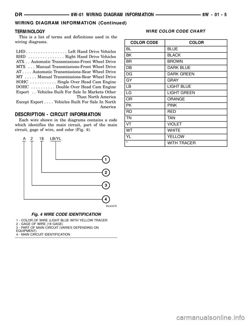
circuit, gage of wire, and color (Fig. 4).
WIRE COLOR CODE CHART
COLOR CODE COLOR
BL BLUE
BK BLACK
BR BROWN
DB DARK BLUE
DG DARK GREEN
GY GRAY
LB LIGHT BLUE
LG LIGHT GREEN
OR ORANGE
PK PINK
RD RED
TN TAN
VT VIOLET
WT WHITE
YL YELLOW
* WITH TRACER
Fig. 4 WIRE CODE IDENTIFICATION
1 - COLOR OF WIRE (LIGHT BLUE WITH YELLOW TRACER
2 - GAGE OF WIRE (18 GAGE)
3 - PART OF MAIN CIRCUIT (VARIES DEPENDING ON
EQUIPMENT)
4 - MAIN CIRCUIT IDENTIFICATION
DR8W-01 WIRING DIAGRAM INFORMATION 8W - 01 - 5
WIRING DIAGRAM INFORMATION (Continued)
Page 734 of 2627

DESCRIPTION - CONNECTOR, GROUND AND
SPLICE INFORMATION
CAUTION: Not all connectors are serviced. Some
connectors are serviced only with a harness. A typ-
ical example might be the Supplemental Restraint
System connectors. Always check parts availability
before attempting a repair.
IDENTIFICATION
In-line connectors are identified by a number, as
follows:
²In-line connectors located in the engine compart-
ment are C100 series numbers
²In-line connectors located in the Instrument
Panel area are C200 series numbers.
²In-line connectors located in the body are C300
series numbers.
²Jumper harness connectors are C400 series
numbers.
²Grounds and ground connectors are identified
with a ªGº and follow the same series numbering as
the in-line connectors.
²Splices are identified with an ªSº and follow the
same series numbering as the in-line connectors.
²Component connectors are identified by the com-
ponent name instead of a number. Multiple connec-
tors on a component use a C1, C2, etc. identifier.
LOCATIONS
Section 8W-91 contains connector/ground/splice
location illustrations. The illustrations contain the
connector name (or number)/ground number/splice
number and component identification. Connector/
ground/splice location charts in section 8W-91 refer-
ence the figure numbers of the illustrations.
The abbreviation T/O is used in the component
location section to indicate a point in which the wir-
ing harness branches out to a component. The abbre-
viation N/S means Not Shown in the illustrations
WARNING
WARNINGS - GENERAL
WARNINGSprovide information to prevent per-
sonal injury and vehicle damage. Below is a list of
general warnings that should be followed any time a
vehicle is being serviced.
WARNING: ALWAYS WEAR SAFETY GLASSES FOR
EYE PROTECTION.
WARNING: USE SAFETY STANDS ANYTIME A PRO-
CEDURE REQUIRES BEING UNDER A VEHICLE.WARNING: BE SURE THAT THE IGNITION SWITCH
ALWAYS IS IN THE OFF POSITION, UNLESS THE
PROCEDURE REQUIRES IT TO BE ON.
WARNING: SET THE PARKING BRAKE WHEN
WORKING ON ANY VEHICLE. AN AUTOMATIC
TRANSMISSION SHOULD BE IN PARK. A MANUAL
TRANSMISSION SHOULD BE IN NEUTRAL.
WARNING: OPERATE THE ENGINE ONLY IN A
WELL-VENTILATED AREA.
WARNING: KEEP AWAY FROM MOVING PARTS
WHEN THE ENGINE IS RUNNING, ESPECIALLY THE
FAN AND BELTS.
WARNING: TO PREVENT SERIOUS BURNS, AVOID
CONTACT WITH HOT PARTS SUCH AS THE RADIA-
TOR, EXHAUST MANIFOLD(S), TAIL PIPE, CATA-
LYTIC CONVERTER AND MUFFLER.
WARNING: DO NOT ALLOW FLAME OR SPARKS
NEAR THE BATTERY. GASES ARE ALWAYS
PRESENT IN AND AROUND THE BATTERY.
WARNING: ALWAYS REMOVE RINGS, WATCHES,
LOOSE HANGING JEWELRY AND AVOID LOOSE
CLOTHING.
DIAGNOSIS AND TESTING - WIRING HARNESS
TROUBLESHOOTING TOOLS
When diagnosing a problem in an electrical circuit
there are several common tools necessary. These tools
are listed and explained below.
²Jumper Wire - This is a test wire used to con-
nect two points of a circuit. It can be used to bypass
an open in a circuit.
WARNING: NEVER USE A JUMPER WIRE ACROSS
A LOAD, SUCH AS A MOTOR, CONNECTED
BETWEEN A BATTERY FEED AND GROUND.
²Voltmeter - Used to check for voltage on a cir-
cuit. Always connect the black lead to a known good
ground and the red lead to the positive side of the
circuit.
CAUTION: Most of the electrical components used
in today's vehicles are Solid State. When checking
voltages in these circuits, use a meter with a 10 -
megohm or greater impedance rating.
DR8W-01 WIRING DIAGRAM INFORMATION 8W - 01 - 7
WIRING DIAGRAM INFORMATION (Continued)
Page 1050 of 2627

8W-80 CONNECTOR PIN-OUTS
Component Page
4WD Switch (Manual Transfer Case)..... 8W-80-5
A/C Compressor Clutch (Diesel)......... 8W-80-5
A/C Compressor Clutch (Gas)........... 8W-80-5
A/C Heater Control C1................ 8W-80-5
A/C Heater Control C2................ 8W-80-6
A/C Pressure Transducer (Diesel)........ 8W-80-6
A/C Pressure Transducer (NGC)......... 8W-80-6
Accelerator Pedal Position Sensor (5.7L) . . 8W-80-6
Accelerator Pedal Position Sensor
(Diesel M/T)...................... 8W-80-7
Accelerator Pedel Position Sensor
(Diesel A/T)....................... 8W-80-7
Adjustable Pedal Motor (Except Memory) . 8W-80-7
Adjustable Pedal Switch (Except Memory) . 8W-80-8
Airbag Control Module C1............. 8W-80-8
Airbag Control Module C2............. 8W-80-9
Airbag-Left Curtain.................. 8W-80-9
Airbag-Passenger On/Off Switch....... 8W-80-10
Airbag-Passenger Squib.............. 8W-80-10
Airbag-Right Curtain................ 8W-80-10
Ambient Temperature Sensor.......... 8W-80-10
Amplifier Audio C1 (Premium)......... 8W-80-11
Amplifier Audio C2 (Premium)......... 8W-80-11
Ashtray Lamp...................... 8W-80-11
Automatic Day/Night Mirror C1 (Except
Base).......................... 8W-80-12
Automatic Day/Night Mirror C2
(Telematics)..................... 8W-80-12
Back-Up Lamp Switch............... 8W-80-12
Battery Temperature Sensor........... 8W-80-12
Blend Door Actuator (Single Zone)...... 8W-80-13
Blower Motor...................... 8W-80-13
Blower Motor Resistor Block.......... 8W-80-13
Brake Fluid Level Switch............. 8W-80-13
Brake Lamp Switch................. 8W-80-13
Brake Transmission Shift Interlock
Solenoid........................ 8W-80-14
C102 (NGC)....................... 8W-80-14
C103............................. 8W-80-14
C106 (5.7L A/T).................... 8W-80-14
C106 (5.7L A/T).................... 8W-80-15
C107 (5.7L)........................ 8W-80-15
C107 (5.7L)........................ 8W-80-16
C108 (Diesel)...................... 8W-80-16
C108 (Diesel)...................... 8W-80-16
C109 (Diesel)...................... 8W-80-17
C109 (Diesel)...................... 8W-80-17
C110 (Diesel)...................... 8W-80-17
C110 (Diesel)...................... 8W-80-18
C112 (Diesel M/T)................... 8W-80-18
C112 (Diesel M/T)................... 8W-80-18
C112 (Diesel A/T)................... 8W-80-18Component Page
C112 (Diesel A/T)................... 8W-80-19
C130 (Diesel)...................... 8W-80-19
C131 (4.7L Electronic Transfer Case).... 8W-80-20
C131 (4.7L Electronic Transfer Case).... 8W-80-20
C131 (5.7L/Diesel).................. 8W-80-20
C131 (5.7L/Diesel).................. 8W-80-21
C131 (3.7L/4.7L Except Electronic
Transfer Case)................... 8W-80-21
C131 (3.7L/4.7L Except Electronic
Transfer Case)................... 8W-80-22
C200............................. 8W-80-22
C200............................. 8W-80-23
C201............................. 8W-80-23
C201............................. 8W-80-23
C202............................. 8W-80-24
C202............................. 8W-80-24
C206............................. 8W-80-24
C206............................. 8W-80-24
C207............................. 8W-80-24
C207............................. 8W-80-25
C216............................. 8W-80-25
C216............................. 8W-80-25
C217............................. 8W-80-26
C217............................. 8W-80-26
C218............................. 8W-80-26
C218............................. 8W-80-27
C219............................. 8W-80-27
C219............................. 8W-80-29
C220............................. 8W-80-30
C220............................. 8W-80-31
C250 (Hands Free).................. 8W-80-31
C250 (Hands Free).................. 8W-80-32
C301............................. 8W-80-32
C301............................. 8W-80-32
C301............................. 8W-80-33
C302............................. 8W-80-33
C302 (SLT)........................ 8W-80-34
C304............................. 8W-80-34
C304............................. 8W-80-34
C305 (SLT)........................ 8W-80-35
C305 (SLT)........................ 8W-80-35
C306............................. 8W-80-36
C306............................. 8W-80-36
C308............................. 8W-80-36
C308............................. 8W-80-37
C309............................. 8W-80-37
C309............................. 8W-80-37
C311 ............................. 8W-80-38
C311 ............................. 8W-80-38
C313............................. 8W-80-38
C313............................. 8W-80-39
C315............................. 8W-80-39
DR8W-80 CONNECTOR PIN-OUTS 8W - 80 - 1
Page 1068 of 2627
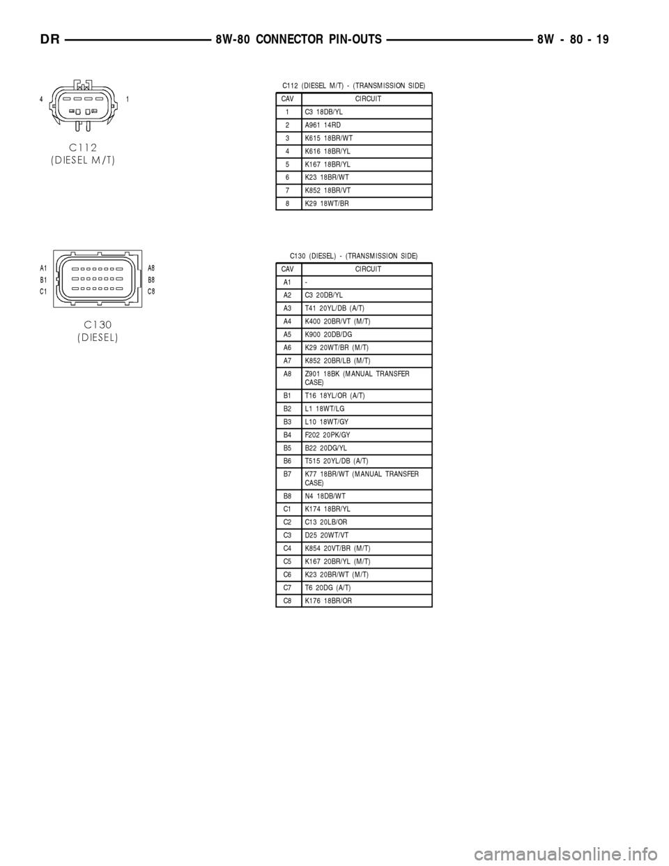
C112 (DIESEL M/T) - (TRANSMISSION SIDE)
CAV CIRCUIT
1 C3 18DB/YL
2 A961 14RD
3 K615 18BR/WT
4 K616 18BR/YL
5 K167 18BR/YL
6 K23 18BR/WT
7 K852 18BR/VT
8 K29 18WT/BR
C130 (DIESEL) - (TRANSMISSION SIDE)
CAV CIRCUIT
A1 -
A2 C3 20DB/YL
A3 T41 20YL/DB (A/T)
A4 K400 20BR/VT (M/T)
A5 K900 20DB/DG
A6 K29 20WT/BR (M/T)
A7 K852 20BR/LB (M/T)
A8 Z901 18BK (MANUAL TRANSFER
CASE)
B1 T16 18YL/OR (A/T)
B2 L1 18WT/LG
B3 L10 18WT/GY
B4 F202 20PK/GY
B5 B22 20DG/YL
B6 T515 20YL/DB (A/T)
B7 K77 18BR/WT (MANUAL TRANSFER
CASE)
B8 N4 18DB/WT
C1 K174 18BR/YL
C2 C13 20LB/OR
C3 D25 20WT/VT
C4 K854 20VT/BR (M/T)
C5 K167 20BR/YL (M/T)
C6 K23 20BR/WT (M/T)
C7 T6 20DG (A/T)
C8 K176 18BR/OR
DR8W-80 CONNECTOR PIN-OUTS 8W - 80 - 19
Page 1154 of 2627
8W-91 CONNECTOR/GROUND/SPLICE LOCATION
TABLE OF CONTENTS
page
CONNECTOR/GROUND/SPLICE LOCATION
DESCRIPTION..........................1
CONNECTOR/GROUND/SPLICE
LOCATION
DESCRIPTION
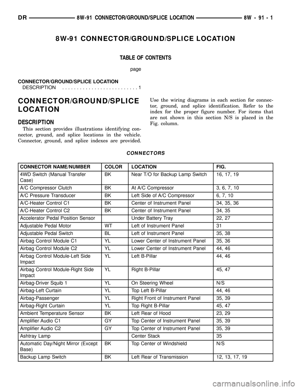
This section provides illustrations identifying con-
nector, ground, and splice locations in the vehicle.
Connector, ground, and splice indexes are provided.Use the wiring diagrams in each section for connec-
tor, ground, and splice identification. Refer to the
index for the proper figure number. For items that
are not shown in this section N/S is placed in the
Fig. column.
CONNECTORS
CONNECTOR NAME/NUMBER COLOR LOCATION FIG.
4WD Switch (Manual Transfer
Case)BK Near T/O for Backup Lamp Switch 16, 17, 19
A/C Compressor Clutch BK At A/C Compressor 3, 6, 7, 10
A/C Pressure Transducer BK Left Side of A/C Compressor 6, 7, 10
A/C-Heater Control C1 BK Center of Instrument Panel 34, 35, 36
A/C-Heater Control C2 BK Center of Instrument Panel 34, 35
Accelerator Pedal Position Sensor Under Battery Tray 22, 27
Adjustable Pedal Motor WT Left of Instrument Panel 31
Adjustable Pedal Switch BL Left of Instrument Panel 35, 38
Airbag Control Module C1 YL Lower Center of Instrument Panel 35, 36
Airbag Control Module C2 YL Lower Center of Instrument Panel 44, 46
Airbag Control Module-Left Side
ImpactYL Left B-Pillar 44, 46
Airbag Control Module-Right Side
ImpactYL Right B-Pillar 45, 47
Airbag-Driver Squib 1 YL On Steering Wheel N/S
Airbag-Left Curtain YL Top Left B-Pillar 44, 46
Airbag-Passenger YL Right Front of Instrument Panel 35, 39
Airbag-Right Curtain YL Top Right B-Pillar 45, 47
Ambient Temperature Sensor BK Left Rear of Hood 23, 29
Amplifier Audio C1 GY Top Center of Instrument Panel 35, 39
Amplifier Audio C2 GY Top Center of Instrument Panel 35, 39
Ashtray Lamp Center Stack 35
Automatic Day/Night Mirror (Except
Base)BK Top Center of Windshield N/S
Backup Lamp Switch BK Left Rear of Transmission 12, 13, 17, 19
DR8W-91 CONNECTOR/GROUND/SPLICE LOCATION 8W - 91 - 1
Page 1176 of 2627

Fig. 12 MANUAL TRANSMISSION (DIESEL)
Fig. 13 FRONT MANUAL TRANSMISSION (DIESEL)
DR8W-91 CONNECTOR/GROUND/SPLICE LOCATION 8W - 91 - 23
CONNECTOR/GROUND/SPLICE LOCATION (Continued)