Fig DODGE RAM 1500 1998 2.G Workshop Manual
[x] Cancel search | Manufacturer: DODGE, Model Year: 1998, Model line: RAM 1500, Model: DODGE RAM 1500 1998 2.GPages: 2627
Page 1556 of 2627

STANDARD PROCEDURE - REAR FRAME
H-SECTION REPLACEMENT
CAUTION: This procedure is designed to replace
the H-section/spare tire support located at the rear
of the frame assembly. Prior to any cutting, the
vehicle must be mounted on the appropriate frame
repair equipment (ªframe rackº), checked with three
dimensional measuring equipment, and the neces-
sary pull corrections made. If damage remains in
the frame beyond the area covered by this service
part after the pull, the frame must be replaced in its
entirety.
(1) Before proceding with this repair procedure
review the required service warnings and precau-
tions. (Refer to 13 - FRAME & BUMPERS/FRAME -
WARNING)
(2) Disconnect and isolate the battery negative
cable.
(3) Remove the cargo box. (Refer to 23 - BODY/EX-
TERIOR/CARGO BOX - REMOVAL)
(4) Remove the trailer hitch. (Refer to 13 - FRAME
& BUMPERS/FRAME/TRAILER HITCH -
REMOVAL)
(5) Raise and support the frame so the tires are off
floor.(6) Remove the shock absorbers. (Refer to 2 - SUS-
PENSION/REAR/SHOCK - REMOVAL)
(7) Remove the rear leaf spring shackle bolts and
let the axle rest on the ground. (Fig. 20)
(8) Remove the spare wheel.
Fig. 19 ENGINE COMPARTMENT/FRONT STRUCTURE
Fig. 20 REAR SPRING
1 - SPRING SHACKLE
2 - LEAF SPRING EYE BOLT/NUT
3 - REAR LEAF SPRING
DRFRAMES & BUMPERS 13 - 13
FRAME (Continued)
Page 1557 of 2627

(9) Remove the clip and remove the spare tire
winch tube. (Fig. 21)
(10) Remove the bolts and remove the spare tire
winch. (Fig. 22)
(11) Position the wire harness forward of the work
area.
CAUTION: Do not use any flame or plasma cutting
equipment to cut the frame in this procedure. The
inaccurate and high temperatures achieved during
flame or plasma cutting will change the metal char-
acteristics and may weaken the frame and/or repair
location.(12) Carefully remove the H-section welds using a
grinder or equivalent tool.
(13) Remove the H-section and clean any remain-
ing welds from the frame.
(14) Trial fit the replacement part.
(15) Remove all e-coat from within 25 mm (1.0 in.)
of the weld area.
(16) Using the appropriate measuring equipment,
position the replacement part and verify correct posi-
tioning in all three (X,Y, and Z) planes of space.
(Refer to 13 - FRAME & BUMPERS/FRAME - SPEC-
IFICATIONS - FRAME DIMENSIONS)
CAUTION: Shield the surrounding area and compo-
nents from exposure to the welding spatter and
heat.
(17) Weld the replacement H-section into position.
The welding should be performed in a skip (stitch)
type method to minimize the heat buildup following
I-CAR or the American Welding Society welding pro-
cedures and utilizing the process specifications at the
end of this section. (Refer to 13 - FRAME &
BUMPERS/FRAME - SPECIFICATIONS - WELD-
ING)
(18) Dress the welded area and apply corrosion
resistant coatings inside and out.
(a) Inside the rail, inject a creeping wax based
rust inhibitor compound through the existing holes
in the frame ensuring 100% coverage including the
mating face between the frame and replacement
H-section.
(b) Apply a durable top coat to the outside of the
repair area.
(19) Position the wiring harness back.
CAUTION: Inspect the tire winch assembly for dam-
age. If any one or more of the following are evident,
replace the winch assembly.
²Indications of cracked or bulging plastic.
²Housing flanges are bent or cracked.
²If winch was loose before repair.
(20) Install the spare tire winch and install the
bolts. (Fig. 22)
(21) Tighten the bolts to 41 N´m (30 ft. lbs.).
(22) Install the spare tire winch tube and install
the clip. (Fig. 21)
(23) Install the spare tire.
CAUTION: Check operation of the spare tire winch
by manipulating it up and down. If the winch binds
or jambs, replace the winch assembly.
(24) Lift the axle into position and install the rear
shackle bolts. (Fig. 20)
(25) Tighten the bolts to 163 N´m (120 ft. lbs.).
Fig. 21 SPARE TIRE WINCH TUBE
1 - SPARE TIRE WINCH ASSEMBLY
2 - HAIR PIN CLIP
3 - WINCH TUBE
4 - H-SECTION/SPARE WHEEL SUPPORT
Fig. 22 SPARE TIRE WINCH ASSEMBLY
1 - SPARE TIRE WINCH ASSEMBLY
2 - BOLTS
3 - RETAINER BRACKET
4 - H-SECTION/SPARE WHEEL SUPPORT
13 - 14 FRAMES & BUMPERSDR
FRAME (Continued)
Page 1559 of 2627

SPECIFICATIONS - FRAME DIMENSIONS
NOTE: Frame dimensions are listed in metric scale.
All dimensions are from center to center of Princi-
pal Locating Point (PLP), or from center to center of
PLP and fastener location.
VEHICLE PREPARATION
Position the vehicle on a level work surface. Using
screw or bottle jacks, adjust the vehicle PLP heights
to the specified dimension above a level work surface.
Vertical dimensions can be taken from the work sur-
face to the locations indicated were applicable.
INDEX
DESCRIPTION FIGURE
Frame Dimensional Graphics, Side
And Top View23
140.5 In Wheelbase - Heavy Duty -
2 Wheel Drive24
140.5 In Wheelbase - Heavy Duty -
4 Wheel Drive25
160.5 In Wheelbase - Heavy Duty -
2 Wheel Drive26
160.5 In Wheelbase - Heavy Duty -
4 Wheel Drive27
13 - 16 FRAMES & BUMPERSDR
FRAME (Continued)
Page 1560 of 2627

Fig. 23 FRAME DIMENSIONS
DRFRAMES & BUMPERS 13 - 17
FRAME (Continued)
Page 1561 of 2627

Fig. 24 140.5 IN WHEELBASE - HEAVY DUTY - 2 WHEEL DRIVE
13 - 18 FRAMES & BUMPERSDR
FRAME (Continued)
Page 1562 of 2627

Fig. 25 140.5 IN WHEELBASE - HEAVY DUTY - 4 WHEEL DRIVE
DRFRAMES & BUMPERS 13 - 19
FRAME (Continued)
Page 1563 of 2627

Fig. 26 160.5 IN WHEELBASE - HEAVY DUTY - 2 WHEEL DRIVE
13 - 20 FRAMES & BUMPERSDR
FRAME (Continued)
Page 1564 of 2627

Fig. 27 160.5 IN WHEELBASE - HEAVY DUTY - 4 WHEEL DRIVE
DRFRAMES & BUMPERS 13 - 21
FRAME (Continued)
Page 1565 of 2627

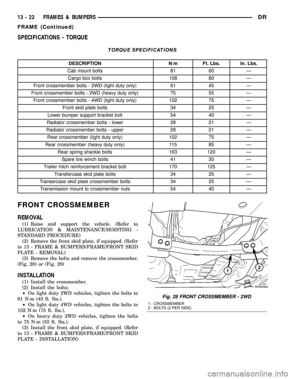
SPECIFICATIONS - TORQUE
TORQUE SPECIFICATIONS
DESCRIPTION N´m Ft. Lbs. In. Lbs.
Cab mount bolts 81 60 Ð
Cargo box bolts 108 80 Ð
Front crossmember bolts - 2WD (light duty only) 61 45 Ð
Front crossmember bolts - 2WD (heavy duty only) 75 55 Ð
Front crossmember bolts - 4WD (light duty only) 102 75 Ð
Front skid plate bolts 34 25 Ð
Lower bumper support bracket bolt 54 40 Ð
Radiator crossmember bolts - lower 28 21 Ð
Radiator crossmember bolts - upper 28 21 Ð
Rear crossmember (light duty only) 102 75 Ð
Rear crossmember (heavy duty only) 115 85 Ð
Rear spring shackle bolts 163 120 Ð
Spare tire winch bolts 41 30 Ð
Trailer hitch reinforcement bracket bolt 170 125 Ð
Transfercase skid plate bolts 34 25 Ð
Transercase skid plate crossmember bolts 34 25 Ð
Transmission mount to crossmember nuts 54 40 Ð
FRONT CROSSMEMBER
REMOVAL
(1) Raise and support the vehicle. (Refer to
LUBRICATION & MAINTENANCE/HOISTING -
STANDARD PROCEDURE)
(2) Remove the front skid plate, if equipped. (Refer
to 13 - FRAME & BUMPERS/FRAME/FRONT SKID
PLATE - REMOVAL)
(3) Remove the bolts and remove the crossmember.
(Fig. 28) or (Fig. 29)
INSTALLATION
(1) Install the crossmember.
(2) Install the bolts;
²On light duty 2WD vehicles, tighten the bolts to
61 N´m (45 ft. lbs.).
²On light duty 4WD vehicles, tighten the bolts to
102 N´m (75 ft. lbs.).
²On heavy duty 2WD vehicles, tighten the bolts
to 75 N´m (55 ft. lbs.).
(3) Install the front skid plate, if equipped. (Refer
to 13 - FRAME & BUMPERS/FRAME/FRONT SKID
PLATE - INSTALLATION)
Fig. 28 FRONT CROSSMEMBER - 2WD
1 - CROSSMEMBER
2 - BOLTS (2 PER SIDE)
13 - 22 FRAMES & BUMPERSDR
FRAME (Continued)
Page 1566 of 2627

FRONT SKID PLATE
REMOVAL
(1) Raise and support the vehicle. (Refer to
LUBRICATION & MAINTENANCE/HOISTING -
STANDARD PROCEDURE)
(2) Remove the bolts. (Fig. 30)
(3) Slide skid plate back off of the crossmember
and remove.
INSTALLATION
(1) Snap the rear tabs over the front crossmember
and install the skid plate.
(2) Install the bolts and tighten to 34 N´m (25 ft.
lbs.).
FRONT TOW HOOK ASSEMBLY
REMOVAL
(1) Remove front bumper. (Refer to 13 - FRAME &
BUMPERS/BUMPERS/FRONT BUMPER -
REMOVAL)
(2) Remove the bolts and remove the tow hook
assembly. (Fig. 31) and (Fig. 32)
INSTALLATION
(1) Install the tow hook assembly and bolts hand
tight.
(2) Install the front bumper. (Refer to 13 - FRAME
& BUMPERS/BUMPERS/FRONT BUMPER -
INSTALLATION)
(3) Tighten the tow hook bolts to 68 N´m (50 ft.
lbs.).
Fig. 29 FRONT CROSSMEMBER - 4WD
1 - BOLTS (2 PER SIDE)
2 - CROSSMEMBER
Fig. 30 FRONT SKID PLATE
1 - FRONT CROSSMEMBER
2 - FRONT SKID PLATE
3 - BOLTS (2)
Fig. 31 FRONT TOW HOOK ASSEMBLY
1 - BUMPER CENTER SUPPORT BRACKET
2 - BOLTS (6)
3 - TOW HOOK ASSEMBLY
DRFRAMES & BUMPERS 13 - 23
FRONT CROSSMEMBER (Continued)