phone DODGE RAM 1500 1998 2.G Workshop Manual
[x] Cancel search | Manufacturer: DODGE, Model Year: 1998, Model line: RAM 1500, Model: DODGE RAM 1500 1998 2.GPages: 2627
Page 705 of 2627

washer system plumbing (Fig. 3). The check valve is
integral to the washer nozzle plumbing wye fitting
located in the cowl plenum area beneath the cowl
plenum cover/grille panel near the base of the wind-
shield. The check valve consists of a molded plastic
body with a raised arrowhead molded into its center
section that indicates the direction of the flow
through the valve, and three barbed hose nipples
formed in a wye configuration on the outside circum-
ference of the center section of the valve body. The
check valve cannot be adjusted or repaired and, if
faulty or damaged, it must be replaced.
OPERATION
The check valve provides more than one function
in this application. It serves as a wye connector fit-
ting between the engine compartment and washer
nozzle sections of the washer supply hose. It prevents
washer fluid from draining out of the washer supply
hoses back to the washer reservoir. This drain-back
would result in a lengthy delay from when the
washer switch is actuated until washer fluid was dis-
pensed through the washer nozzles, because the
washer pump would have to refill the washer plumb-
ing from the reservoir to the nozzles. Such a drain-
back condition could also result in water, dirt, or
other outside contaminants being siphoned into the
washer system through the washer nozzle orifice.
This water could subsequently freeze and plug the
nozzle, while other contaminants could interfere with
proper nozzle operation and cause improper nozzle
spray patterns. In addition, the check valve prevents
washer fluid from siphoning through the washer noz-
zles after the washer system is turned Off.When the washer pump pressurizes and pumps
washer fluid from the reservoir through the washer
plumbing, the fluid pressure unseats a diaphragm
from over a sump well within the valve by overriding
the spring pressure applied to it by a piston (Fig. 4).
With the diaphragm unseated, washer fluid is
allowed to flow toward the two washer nozzles. When
the washer pump stops operating, the spring pres-
sure on the piston seats the diaphragm over the
sump well in the valve and fluid flow in either direc-
tion within the washer plumbing is prevented. The
check valve cannot be adjusted or repaired and, if
faulty or damaged, it must be replaced.REMOVAL
(1) Remove both wiper arms from the wiper pivots.
(Refer to 8 - ELECTRICAL/WIPERS/WASHERS/
WIPER ARM - REMOVAL).
(2) Unlatch and open the hood.
(3) Remove the cowl plenum cover/grille panel
from over the cowl plenum. (Refer to 23 - BODY/EX-
TERIOR/COWL GRILLE - REMOVAL).
(4) From the underside of the cowl plenum cover/
grille panel, disconnect the cowl plenum and washer
nozzle hoses from the three barbed nipples of the
check valve (Fig. 5).
(5) Remove the check valve from the underside of
the cowl plenum cover/grille panel.
INSTALLATION
(1) Position the check valve to the underside of the
cowl plenum cover/grille panel (Fig. 5). Be certain
that the flow direction arrow molded into the check
valve body is oriented towards the washer nozzles.
Fig. 3 Check Valve
1 - INLET NIPPLE
2 - CHECK VALVE
3 - OUTLET NIPPLE (2)
4 - FLOW DIRECTION ARROW
Fig. 4 Check Valve
1 - SPRING
2 - PISTON
3 - DIAPHRAGM
4 - TO WASHER NOZZLE
5 - FROM WASHER PUMP
8R - 8 WIPERS/WASHERSDR
CHECK VALVE (Continued)
Page 724 of 2627

NAVIGATION/TELECOMMUNICATION
TABLE OF CONTENTS
page page
NAVIGATION/TELECOMMUNICATION
DESCRIPTION..........................1
OPERATION............................1HANDS FREE MODULE
REMOVAL.............................2
INSTALLATION..........................2
NAVIGATION/
TELECOMMUNICATION
DESCRIPTION
TELECOMMUNICATIONS
The hands-free cellular system on this vehicle uses
BluetoothŸ technology to provide wireless communi-
cation between the operator's compatible cellular
telephone and the vehicle's on-board receiver.
The system uses voice recognition technology to
control operation. The incoming voice is broadcast
through the vehicle's radio speakers, automatically
overriding any other audio signals on the front
speakers when the hands-free system is in use. A
microphone in the rearview mirror picks up vehicle
occupant's voices. If a call is in progress when the
ignition is switched off, the hands-free system will
continue to operate for up to 45 seconds as part of
the Accessory Relay Delay function. Thereafter, the
call can continue on the hand-held telephone.
The system will communicate with a telephone
that is anywhere within the vehicle. However, cover-
ing the hand held phone or the hands-free phone
module with a metal object may block the signal. The
system will recognize up to seven telephones, each of
which is given a spoken identification by the user
during the setup process. The system includes Span-
ish and French voice recognition in addition to
English.
Two buttons on the rearview mirror, identified with
ISO icons, control the system: A9phone9button turns
the system on and off; a9voice recognition9(or voice
command) button prompts the hands-free system to
listen for a voice command.
OPERATION
TELECOMMUNICATION
Two buttons on the rearview mirror, identified with
ISO icons, control the system: A9phone9button turns
the system on and off; a9voice recognition9(or voice
command) button prompts the hands-free system to
listen for a voice command. The system includes the
following features:
²Phone book - Stores telephone numbers for later
recall by name or other verbal identification, called a
voice tag, and memory location.
²Four memory locations - Home, Work, Cellular
and Pager. A maximum of 32 unique names or voice
tags may be stored at the same time, with a different
number in each of the four memory locations.
²Voice tag dialing - Dials the number associated
with a voice tag and memory location.
²Digit dialing - Dials the telephone number by
recognizing the names of the digits as they are spo-
ken.
²Receiving calls - A voice prompt notifies the user
of an incoming call. A voice response accepts or
rejects the call without manual intervention.
²Privacy Mode - Switches the call to the hand-
held telephone and the hands-free system and back
again using the ªvoice recognitionº (or ªvoice com-
mandº) button and a voice command, if desired.
DRNAVIGATION/TELECOMMUNICATION 8T - 1
Page 1061 of 2627

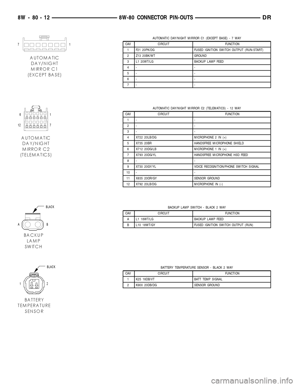
AUTOMATIC DAY/NIGHT MIRROR C1 (EXCEPT BASE)-7WAY
CAV CIRCUIT FUNCTION
1 F21 20PK/DG FUSED IGNITION SWITCH OUTPUT (RUN-START)
2 Z13 20BK/WT GROUND
3 L1 20WT/LG BACKUP LAMP FEED
4- -
5- -
6- -
7- -
AUTOMATIC DAY/NIGHT MIRROR C2 (TELEMATICS) - 12 WAY
CAV CIRCUIT FUNCTION
1- -
2- -
3- -
4 X722 20LB/DG MICROPHONE 2 IN (+)
5 X735 20BR HANDSFREE MICROPHONE SHIELD
6 X712 20DG/LB MICROPHONE 1 IN (+)
7 X793 20DG/YL HANDSFREE MICROPHONE HSD FEED
8- -
9 X730 20GY/YL VOICE RECOGNITION/PHONE SWITCH SIGNAL
10 - -
11 X835 20OR/GY SENSOR GROUND
12 X792 20LB/DG MICROPHONE IN (-)
BACKUP LAMP SWITCH - BLACK 2 WAY
CAV CIRCUIT FUNCTION
A L1 18WT/LG BACKUP LAMP FEED
B L10 18WT/GY FUSED IGNITION SWITCH OUTPUT (RUN)
BATTERY TEMPERATURE SENSOR - BLACK 2 WAY
CAV CIRCUIT FUNCTION
1 K25 18DB/VT BATT TEMP SIGNAL
2 K900 20DB/DG SENSOR GROUND
8W - 80 - 12 8W-80 CONNECTOR PIN-OUTSDR
Page 1116 of 2627

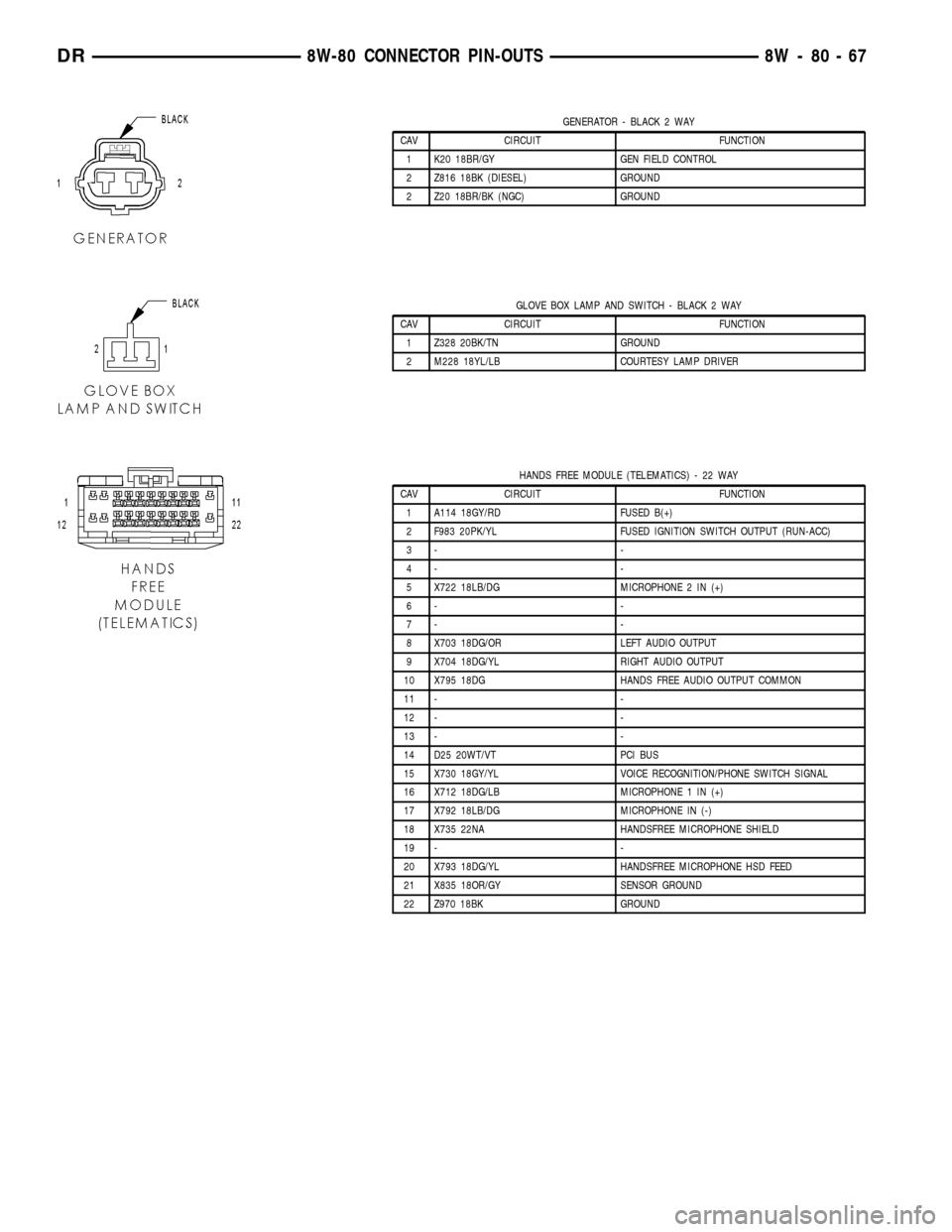
GENERATOR - BLACK 2 WAY
CAV CIRCUIT FUNCTION
1 K20 18BR/GY GEN FIELD CONTROL
2 Z816 18BK (DIESEL) GROUND
2 Z20 18BR/BK (NGC) GROUND
GLOVE BOX LAMP AND SWITCH - BLACK 2 WAY
CAV CIRCUIT FUNCTION
1 Z328 20BK/TN GROUND
2 M228 18YL/LB COURTESY LAMP DRIVER
HANDS FREE MODULE (TELEMATICS) - 22 WAY
CAV CIRCUIT FUNCTION
1 A114 18GY/RD FUSED B(+)
2 F983 20PK/YL FUSED IGNITION SWITCH OUTPUT (RUN-ACC)
3- -
4- -
5 X722 18LB/DG MICROPHONE 2 IN (+)
6- -
7- -
8 X703 18DG/OR LEFT AUDIO OUTPUT
9 X704 18DG/YL RIGHT AUDIO OUTPUT
10 X795 18DG HANDS FREE AUDIO OUTPUT COMMON
11 - -
12 - -
13 - -
14 D25 20WT/VT PCI BUS
15 X730 18GY/YL VOICE RECOGNITION/PHONE SWITCH SIGNAL
16 X712 18DG/LB MICROPHONE 1 IN (+)
17 X792 18LB/DG MICROPHONE IN (-)
18 X735 22NA HANDSFREE MICROPHONE SHIELD
19 - -
20 X793 18DG/YL HANDSFREE MICROPHONE HSD FEED
21 X835 18OR/GY SENSOR GROUND
22 Z970 18BK GROUND
DR8W-80 CONNECTOR PIN-OUTS 8W - 80 - 67