Trans temp DODGE RAM 1500 1998 2.G Manual Online
[x] Cancel search | Manufacturer: DODGE, Model Year: 1998, Model line: RAM 1500, Model: DODGE RAM 1500 1998 2.GPages: 2627
Page 1063 of 2627
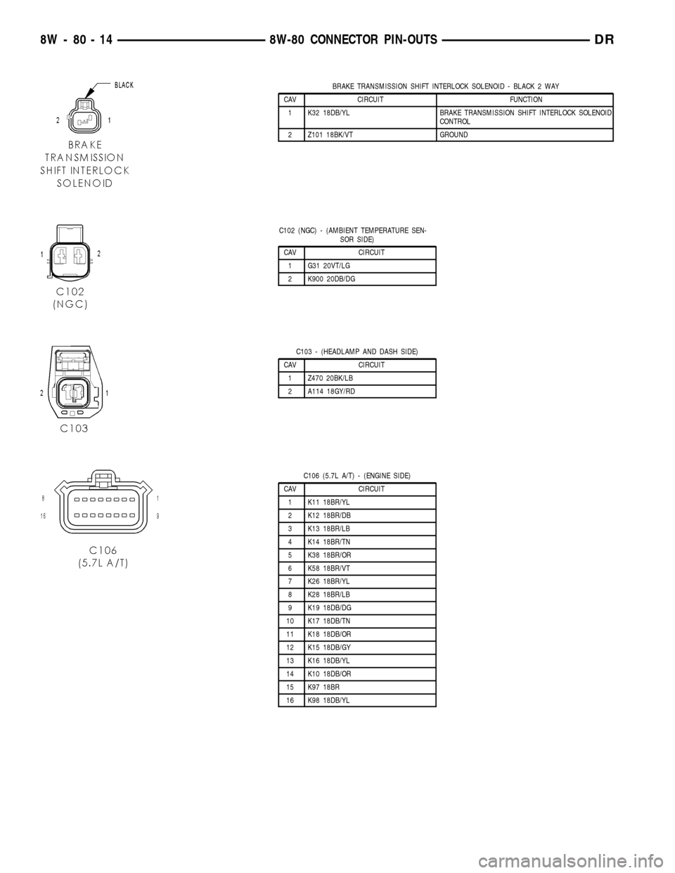
BRAKE TRANSMISSION SHIFT INTERLOCK SOLENOID - BLACK 2 WAY
CAV CIRCUIT FUNCTION
1 K32 18DB/YL BRAKE TRANSMISSION SHIFT INTERLOCK SOLENOID
CONTROL
2 Z101 18BK/VT GROUND
C102 (NGC) - (AMBIENT TEMPERATURE SEN-
SOR SIDE)
CAV CIRCUIT
1 G31 20VT/LG
2 K900 20DB/DG
C103 - (HEADLAMP AND DASH SIDE)
CAV CIRCUIT
1 Z470 20BK/LB
2 A114 18GY/RD
C106 (5.7L A/T) - (ENGINE SIDE)
CAV CIRCUIT
1 K11 18BR/YL
2 K12 18BR/DB
3 K13 18BR/LB
4 K14 18BR/TN
5 K38 18BR/OR
6 K58 18BR/VT
7 K26 18BR/YL
8 K28 18BR/LB
9 K19 18DB/DG
10 K17 18DB/TN
11 K18 18DB/OR
12 K15 18DB/GY
13 K16 18DB/YL
14 K10 18DB/OR
15 K97 18BR
16 K98 18DB/YL
8W - 80 - 14 8W-80 CONNECTOR PIN-OUTSDR
Page 1109 of 2627
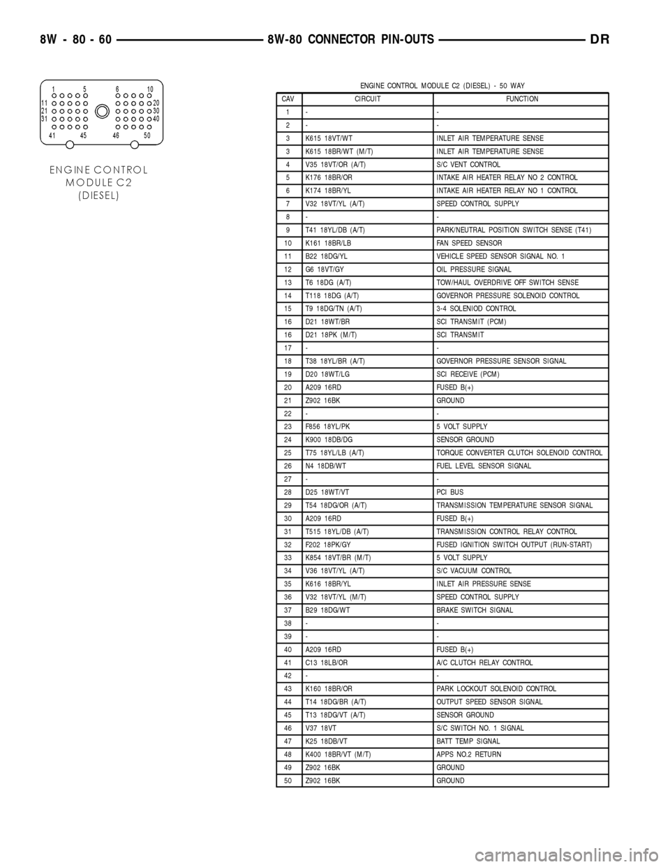
ENGINE CONTROL MODULE C2 (DIESEL) - 50 WAY
CAV CIRCUIT FUNCTION
1- -
2- -
3 K615 18VT/WT INLET AIR TEMPERATURE SENSE
3 K615 18BR/WT (M/T) INLET AIR TEMPERATURE SENSE
4 V35 18VT/OR (A/T) S/C VENT CONTROL
5 K176 18BR/OR INTAKE AIR HEATER RELAY NO 2 CONTROL
6 K174 18BR/YL INTAKE AIR HEATER RELAY NO 1 CONTROL
7 V32 18VT/YL (A/T) SPEED CONTROL SUPPLY
8- -
9 T41 18YL/DB (A/T) PARK/NEUTRAL POSITION SWITCH SENSE (T41)
10 K161 18BR/LB FAN SPEED SENSOR
11 B22 18DG/YL VEHICLE SPEED SENSOR SIGNAL NO. 1
12 G6 18VT/GY OIL PRESSURE SIGNAL
13 T6 18DG (A/T) TOW/HAUL OVERDRIVE OFF SWITCH SENSE
14 T118 18DG (A/T) GOVERNOR PRESSURE SOLENOID CONTROL
15 T9 18DG/TN (A/T) 3-4 SOLENIOD CONTROL
16 D21 18WT/BR SCI TRANSMIT (PCM)
16 D21 18PK (M/T) SCI TRANSMIT
17 - -
18 T38 18YL/BR (A/T) GOVERNOR PRESSURE SENSOR SIGNAL
19 D20 18WT/LG SCI RECEIVE (PCM)
20 A209 16RD FUSED B(+)
21 Z902 16BK GROUND
22 - -
23 F856 18YL/PK 5 VOLT SUPPLY
24 K900 18DB/DG SENSOR GROUND
25 T75 18YL/LB (A/T) TORQUE CONVERTER CLUTCH SOLENOID CONTROL
26 N4 18DB/WT FUEL LEVEL SENSOR SIGNAL
27 - -
28 D25 18WT/VT PCI BUS
29 T54 18DG/OR (A/T) TRANSMISSION TEMPERATURE SENSOR SIGNAL
30 A209 16RD FUSED B(+)
31 T515 18YL/DB (A/T) TRANSMISSION CONTROL RELAY CONTROL
32 F202 18PK/GY FUSED IGNITION SWITCH OUTPUT (RUN-START)
33 K854 18VT/BR (M/T) 5 VOLT SUPPLY
34 V36 18VT/YL (A/T) S/C VACUUM CONTROL
35 K616 18BR/YL INLET AIR PRESSURE SENSE
36 V32 18VT/YL (M/T) SPEED CONTROL SUPPLY
37 B29 18DG/WT BRAKE SWITCH SIGNAL
38 - -
39 - -
40 A209 16RD FUSED B(+)
41 C13 18LB/OR A/C CLUTCH RELAY CONTROL
42 - -
43 K160 18BR/OR PARK LOCKOUT SOLENOID CONTROL
44 T14 18DG/BR (A/T) OUTPUT SPEED SENSOR SIGNAL
45 T13 18DG/VT (A/T) SENSOR GROUND
46 V37 18VT S/C SWITCH NO. 1 SIGNAL
47 K25 18DB/VT BATT TEMP SIGNAL
48 K400 18BR/VT (M/T) APPS NO.2 RETURN
49 Z902 16BK GROUND
50 Z902 16BK GROUND
8W - 80 - 60 8W-80 CONNECTOR PIN-OUTSDR
Page 1140 of 2627

POWERTRAIN CONTROL MODULE C4 (NGC) - GREEN 38 WAY
CAV CIRCUIT FUNCTION
1 T60 18YL/GY OVERDRIVE SOLENOID CONTROL
2 T259 18YL/DG 4C SOLENOID CONTROL
3- -
4 T118 18DG MS SOLENOID CONTROL
5- -
6 T219 18YL/LG 2C SOLENOID CONTROL
7- -
8 T59 18YL/LB UNDERDRIVE SOLENOID CONTROL
9- -
10 T20 18DG/WT L/R SOLENOID CONTROL
11 T140 18YL/GY PRESSURE CONTROL SOLENOID CONTROL
12 Z908 18BK GROUND
13 Z977 18BK GROUND
14 Z904 18BK (A/T) GROUND
15 T1 18DG/LB TRS T1 SENSE
16 T3 18DG/DB TRS T3 SENSE
17 T6 18DG TOW/HAUL OVERDRIVE OFF SWITCH SENSE
18 T515 20YL/DB TRANSMISSION CONTROL RELAY CONTROL
19 T16 18YL/OR TRANSMISSION CONTROL RELAY OUTPUT
20 T48 18BR/YL 4C PRESSURE SWITCH SENSE
21 T29 18YL/WT UNDERDRIVE PRESSURE SWITCH SENSE
22 T9 18DG/TN OVERDRIVE PRESSURE SWITCH SENSE
23 - -
24 - -
25 - -
26 T4 18DG/LB TRS T2 SENSE
27 - -
28 T16 18YL/OR TRANSMISSION CONTROL RELAY OUTPUT
29 T50 18YL/TN LOW/REVERSE PRESSURE SWITCH SENSE
30 T147 18DG/YL 2C PRESSURE SWITCH SENSE
31 T38 18YL/BR LINE PRESSURE SENSOR SIGNAL
32 T14 18DG/BR OUTPUT SPEED SENSOR SIGNAL
33 T52 18DG/OR INPUT SPEED SENSOR SIGNAL
34 T13 18DG/VT SPEED SENSOR GROUND
35 T54 18DG/OR TRANSMISSION TEMPERATURE SENSOR SIGNAL
36 - -
37 T42 18DG/YL TRS T42 SENSE
38 T16 18YL/OR TRANSMISSION CONTROL RELAY OUTPUT
DR8W-80 CONNECTOR PIN-OUTS 8W - 80 - 91
Page 1151 of 2627
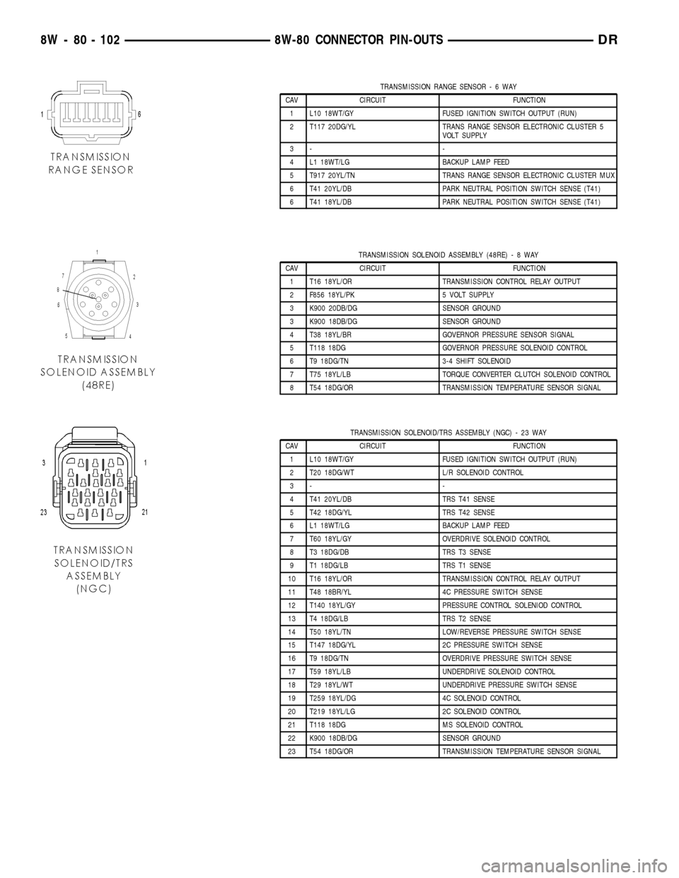
TRANSMISSION RANGE SENSOR-6WAY
CAV CIRCUIT FUNCTION
1 L10 18WT/GY FUSED IGNITION SWITCH OUTPUT (RUN)
2 T117 20DG/YL TRANS RANGE SENSOR ELECTRONIC CLUSTER 5
VOLT SUPPLY
3- -
4 L1 18WT/LG BACKUP LAMP FEED
5 T917 20YL/TN TRANS RANGE SENSOR ELECTRONIC CLUSTER MUX
6 T41 20YL/DB PARK NEUTRAL POSITION SWITCH SENSE (T41)
6 T41 18YL/DB PARK NEUTRAL POSITION SWITCH SENSE (T41)
TRANSMISSION SOLENOID ASSEMBLY (48RE)-8WAY
CAV CIRCUIT FUNCTION
1 T16 18YL/OR TRANSMISSION CONTROL RELAY OUTPUT
2 F856 18YL/PK 5 VOLT SUPPLY
3 K900 20DB/DG SENSOR GROUND
3 K900 18DB/DG SENSOR GROUND
4 T38 18YL/BR GOVERNOR PRESSURE SENSOR SIGNAL
5 T118 18DG GOVERNOR PRESSURE SOLENOID CONTROL
6 T9 18DG/TN 3-4 SHIFT SOLENOID
7 T75 18YL/LB TORQUE CONVERTER CLUTCH SOLENOID CONTROL
8 T54 18DG/OR TRANSMISSION TEMPERATURE SENSOR SIGNAL
TRANSMISSION SOLENOID/TRS ASSEMBLY (NGC) - 23 WAY
CAV CIRCUIT FUNCTION
1 L10 18WT/GY FUSED IGNITION SWITCH OUTPUT (RUN)
2 T20 18DG/WT L/R SOLENOID CONTROL
3- -
4 T41 20YL/DB TRS T41 SENSE
5 T42 18DG/YL TRS T42 SENSE
6 L1 18WT/LG BACKUP LAMP FEED
7 T60 18YL/GY OVERDRIVE SOLENOID CONTROL
8 T3 18DG/DB TRS T3 SENSE
9 T1 18DG/LB TRS T1 SENSE
10 T16 18YL/OR TRANSMISSION CONTROL RELAY OUTPUT
11 T48 18BR/YL 4C PRESSURE SWITCH SENSE
12 T140 18YL/GY PRESSURE CONTROL SOLENIOD CONTROL
13 T4 18DG/LB TRS T2 SENSE
14 T50 18YL/TN LOW/REVERSE PRESSURE SWITCH SENSE
15 T147 18DG/YL 2C PRESSURE SWITCH SENSE
16 T9 18DG/TN OVERDRIVE PRESSURE SWITCH SENSE
17 T59 18YL/LB UNDERDRIVE SOLENOID CONTROL
18 T29 18YL/WT UNDERDRIVE PRESSURE SWITCH SENSE
19 T259 18YL/DG 4C SOLENOID CONTROL
20 T219 18YL/LG 2C SOLENOID CONTROL
21 T118 18DG MS SOLENOID CONTROL
22 K900 18DB/DG SENSOR GROUND
23 T54 18DG/OR TRANSMISSION TEMPERATURE SENSOR SIGNAL
8W - 80 - 102 8W-80 CONNECTOR PIN-OUTSDR
Page 1154 of 2627
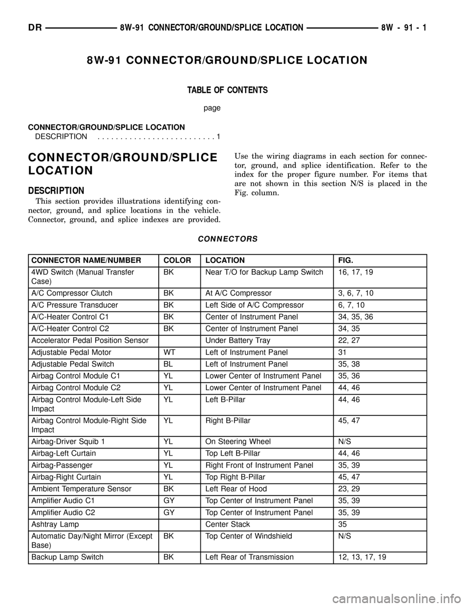
8W-91 CONNECTOR/GROUND/SPLICE LOCATION
TABLE OF CONTENTS
page
CONNECTOR/GROUND/SPLICE LOCATION
DESCRIPTION..........................1
CONNECTOR/GROUND/SPLICE
LOCATION
DESCRIPTION
This section provides illustrations identifying con-
nector, ground, and splice locations in the vehicle.
Connector, ground, and splice indexes are provided.Use the wiring diagrams in each section for connec-
tor, ground, and splice identification. Refer to the
index for the proper figure number. For items that
are not shown in this section N/S is placed in the
Fig. column.
CONNECTORS
CONNECTOR NAME/NUMBER COLOR LOCATION FIG.
4WD Switch (Manual Transfer
Case)BK Near T/O for Backup Lamp Switch 16, 17, 19
A/C Compressor Clutch BK At A/C Compressor 3, 6, 7, 10
A/C Pressure Transducer BK Left Side of A/C Compressor 6, 7, 10
A/C-Heater Control C1 BK Center of Instrument Panel 34, 35, 36
A/C-Heater Control C2 BK Center of Instrument Panel 34, 35
Accelerator Pedal Position Sensor Under Battery Tray 22, 27
Adjustable Pedal Motor WT Left of Instrument Panel 31
Adjustable Pedal Switch BL Left of Instrument Panel 35, 38
Airbag Control Module C1 YL Lower Center of Instrument Panel 35, 36
Airbag Control Module C2 YL Lower Center of Instrument Panel 44, 46
Airbag Control Module-Left Side
ImpactYL Left B-Pillar 44, 46
Airbag Control Module-Right Side
ImpactYL Right B-Pillar 45, 47
Airbag-Driver Squib 1 YL On Steering Wheel N/S
Airbag-Left Curtain YL Top Left B-Pillar 44, 46
Airbag-Passenger YL Right Front of Instrument Panel 35, 39
Airbag-Right Curtain YL Top Right B-Pillar 45, 47
Ambient Temperature Sensor BK Left Rear of Hood 23, 29
Amplifier Audio C1 GY Top Center of Instrument Panel 35, 39
Amplifier Audio C2 GY Top Center of Instrument Panel 35, 39
Ashtray Lamp Center Stack 35
Automatic Day/Night Mirror (Except
Base)BK Top Center of Windshield N/S
Backup Lamp Switch BK Left Rear of Transmission 12, 13, 17, 19
DR8W-91 CONNECTOR/GROUND/SPLICE LOCATION 8W - 91 - 1
Page 1155 of 2627
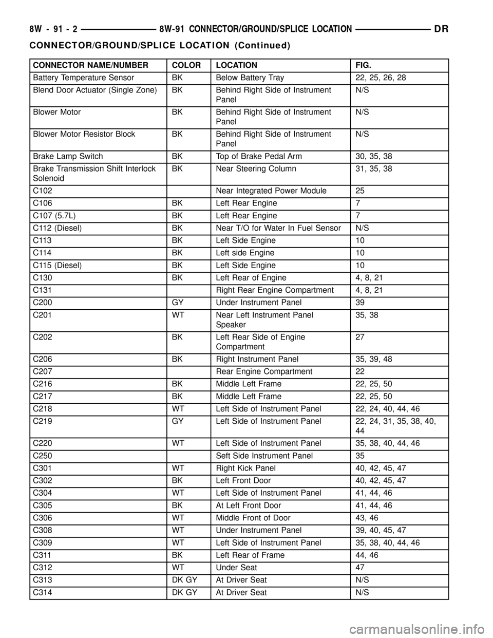
CONNECTOR NAME/NUMBER COLOR LOCATION FIG.
Battery Temperature Sensor BK Below Battery Tray 22, 25, 26, 28
Blend Door Actuator (Single Zone) BK Behind Right Side of Instrument
PanelN/S
Blower Motor BK Behind Right Side of Instrument
PanelN/S
Blower Motor Resistor Block BK Behind Right Side of Instrument
PanelN/S
Brake Lamp Switch BK Top of Brake Pedal Arm 30, 35, 38
Brake Transmission Shift Interlock
SolenoidBK Near Steering Column 31, 35, 38
C102 Near Integrated Power Module 25
C106 BK Left Rear Engine 7
C107 (5.7L) BK Left Rear Engine 7
C112 (Diesel) BK Near T/O for Water In Fuel Sensor N/S
C113 BK Left Side Engine 10
C114 BK Left side Engine 10
C115 (Diesel) BK Left Side Engine 10
C130 BK Left Rear of Engine 4, 8, 21
C131 Right Rear Engine Compartment 4, 8, 21
C200 GY Under Instrument Panel 39
C201 WT Near Left Instrument Panel
Speaker35, 38
C202 BK Left Rear Side of Engine
Compartment27
C206 BK Right Instrument Panel 35, 39, 48
C207 Rear Engine Compartment 22
C216 BK Middle Left Frame 22, 25, 50
C217 BK Middle Left Frame 22, 25, 50
C218 WT Left Side of Instrument Panel 22, 24, 40, 44, 46
C219 GY Left Side of Instrument Panel 22, 24, 31, 35, 38, 40,
44
C220 WT Left Side of Instrument Panel 35, 38, 40, 44, 46
C250 Seft Side Instrument Panel 35
C301 WT Right Kick Panel 40, 42, 45, 47
C302 BK Left Front Door 40, 42, 45, 47
C304 WT Left Side of Instrument Panel 41, 44, 46
C305 BK At Left Front Door 41, 44, 46
C306 WT Middle Front of Door 43, 46
C308 WT Under Instrument Panel 39, 40, 45, 47
C309 WT Left Side of Instrument Panel 35, 38, 40, 44, 46
C311 BK Left Rear of Frame 44, 46
C312 WT Under Seat 47
C313 DK GY At Driver Seat N/S
C314 DK GY At Driver Seat N/S
8W - 91 - 2 8W-91 CONNECTOR/GROUND/SPLICE LOCATIONDR
CONNECTOR/GROUND/SPLICE LOCATION (Continued)
Page 1158 of 2627
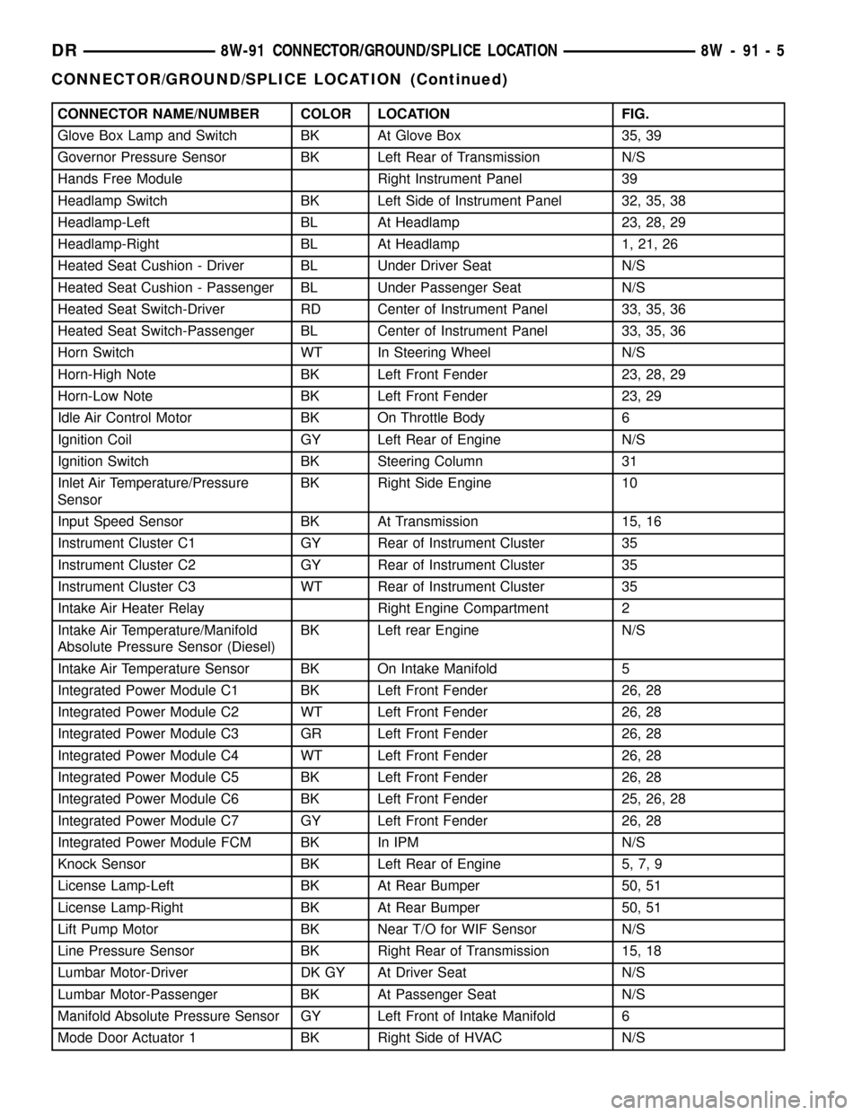
CONNECTOR NAME/NUMBER COLOR LOCATION FIG.
Glove Box Lamp and Switch BK At Glove Box 35, 39
Governor Pressure Sensor BK Left Rear of Transmission N/S
Hands Free Module Right Instrument Panel 39
Headlamp Switch BK Left Side of Instrument Panel 32, 35, 38
Headlamp-Left BL At Headlamp 23, 28, 29
Headlamp-Right BL At Headlamp 1, 21, 26
Heated Seat Cushion - Driver BL Under Driver Seat N/S
Heated Seat Cushion - Passenger BL Under Passenger Seat N/S
Heated Seat Switch-Driver RD Center of Instrument Panel 33, 35, 36
Heated Seat Switch-Passenger BL Center of Instrument Panel 33, 35, 36
Horn Switch WT In Steering Wheel N/S
Horn-High Note BK Left Front Fender 23, 28, 29
Horn-Low Note BK Left Front Fender 23, 29
Idle Air Control Motor BK On Throttle Body 6
Ignition Coil GY Left Rear of Engine N/S
Ignition Switch BK Steering Column 31
Inlet Air Temperature/Pressure
SensorBK Right Side Engine 10
Input Speed Sensor BK At Transmission 15, 16
Instrument Cluster C1 GY Rear of Instrument Cluster 35
Instrument Cluster C2 GY Rear of Instrument Cluster 35
Instrument Cluster C3 WT Rear of Instrument Cluster 35
Intake Air Heater Relay Right Engine Compartment 2
Intake Air Temperature/Manifold
Absolute Pressure Sensor (Diesel)BK Left rear Engine N/S
Intake Air Temperature Sensor BK On Intake Manifold 5
Integrated Power Module C1 BK Left Front Fender 26, 28
Integrated Power Module C2 WT Left Front Fender 26, 28
Integrated Power Module C3 GR Left Front Fender 26, 28
Integrated Power Module C4 WT Left Front Fender 26, 28
Integrated Power Module C5 BK Left Front Fender 26, 28
Integrated Power Module C6 BK Left Front Fender 25, 26, 28
Integrated Power Module C7 GY Left Front Fender 26, 28
Integrated Power Module FCM BK In IPM N/S
Knock Sensor BK Left Rear of Engine 5, 7, 9
License Lamp-Left BK At Rear Bumper 50, 51
License Lamp-Right BK At Rear Bumper 50, 51
Lift Pump Motor BK Near T/O for WIF Sensor N/S
Line Pressure Sensor BK Right Rear of Transmission 15, 18
Lumbar Motor-Driver DK GY At Driver Seat N/S
Lumbar Motor-Passenger BK At Passenger Seat N/S
Manifold Absolute Pressure Sensor GY Left Front of Intake Manifold 6
Mode Door Actuator 1 BK Right Side of HVAC N/S
DR8W-91 CONNECTOR/GROUND/SPLICE LOCATION 8W - 91 - 5
CONNECTOR/GROUND/SPLICE LOCATION (Continued)
Page 1221 of 2627

requires the use of a DRB IIItscan tool and the
proper Body Diagnostic Procedures manual.
Before any testing of the front control module is
attempted, the battery should be fully charged and
all wire harness and ground connections inspected
around the affected areas on the vehicle.
REMOVAL
(1) Disconnect the positive and negative battery
cables from the battery.
(2) Partially remove the integrated power module
from the engine compartment (Refer to 8 - ELECTRI-
CAL/POWER DISTRIBUTION/INTEGRATED
POWER MODULE - REMOVAL).
(3) Remove the front control module retaining
screws.
(4) Using both hands, pull the front control module
straightfrom the integrated power module assembly
to disconnect the 49-way electrical connector and
remove the front control module from the vehicle.
INSTALLATION
(1) Install the front control module on the inte-
grated power module assembly by pushing the
49-way electrical connector straight in.
(2) Install the front control module retaining
screws. Torque the screws to 7 in. lbs.
(3) Install the integrated power module (Refer to 8
- ELECTRICAL/POWER DISTRIBUTION/INTE-
GRATED POWER MODULE - INSTALLATION).
(4) Connect the positive and negative battery
cables.
IOD FUSE
DESCRIPTION
All vehicles are equipped with an Ignition-Off
Draw (IOD) fuse that is disconnected within the Inte-
grated Power Module when the vehicle is shipped
from the factory. Dealer personnel are to reconnect
the IOD fuse in the Integrated Power Module as part
of the preparation procedures performed just prior to
new vehicle delivery.
A laser printed fuse layout map is integral to the
Integrated Power Module cover to ensure proper fuse
identification. The IOD fuse is a 20 ampere mini
blade-type fuse, located in fuse cavity # 51 (Fig. 6).
The fuse is secured within a black molded plastic
fuse holder and puller unit that serves both as a tool
for disconnecting and reconnecting the fuse in its
Integrated Power Module cavity, and as a fuse holder
that conveniently stores the fuse in the same Inte-
grated Power Module cavity after it has been discon-
nected.
CIRCUITS INCLUDED WITH IOD FUSE
²Cluster (CCN)
²Diagnostic Connector
²Map Lamps
²Glove Box Lamp
²Courtesy Lamps
²Radio
²Underhood Lamp
OPERATION
The term ignition-off draw identifies a normal con-
dition where power is being drained from the battery
with the ignition switch in the Off position. The IOD
fuse feeds the memory and sleep mode functions for
some of the electronic modules in the vehicle as well
as various other accessories that require battery cur-
rent when the ignition switch is in the Off position.
The only reason the IOD fuse is disconnected is to
reduce the normal IOD of the vehicle electrical sys-
tem during new vehicle transportation and pre-deliv-
ery storage to reduce battery depletion, while still
allowing vehicle operation so that the vehicle can be
loaded, unloaded and moved as needed by both vehi-
cle transportation company and dealer personnel.
The IOD fuse is disconnected from Integrated
Power Module fuse cavity # 51 when the vehicle is
shipped from the assembly plant. Dealer personnel
must reconnect the IOD fuse when the vehicle is
being prepared for delivery in order to restore full
electrical system operation. Once the vehicle is pre-
pared for delivery, the IOD function of this fuse
Fig. 6 IOD FUSE LOCATION
1 - IOD FUSE
8W - 97 - 6 8W-97 POWER DISTRIBUTIONDR
FRONT CONTROL MODULE (Continued)
Page 1234 of 2627

(12) Disconnect heater hoses from heater core and
remove hose assembly.
(13) Disconnect throttle and speed control cables.
(14) Remove upper radiator hose from engine.
(15) Remove lower radiator hose from engine.
(16) Remove radiator/cooling module assembly.
(17) Disconnect the engine to body ground straps
at the left side of cowl.
(18) Disconnect the engine wiring harness at the
following points:
²Intake air temperature (IAT) sensor
²Fuel Injectors
²Throttle Position (TPS) Switch
²Idle Air Control (IAC) Motor
²Engine Oil Pressure Switch
²Engine Coolant Temperature (ECT) Sensor
²Manifold Absolute Pressure MAP) Sensor
²Camshaft Position (CMP) Sensor
²Coil Over Plugs
²Crankshaft Position Sensor
(19) Remove coil over plugs.
(20) Release fuel rail pressure.
(21) Remove fuel rail and secure away from
engine.
NOTE: It is not necessary to release the quick con-
nect fitting from the fuel supply line for engine
removal.
(22) Remove the PCV hose.
(23) Remove the breather hoses.
(24) Remove the vacuum hose for the power brake
booster.
(25) Disconnect knock sensors.
(26) Remove engine oil dipstick tube.
(27) Remove intake manifold.
(28) Install engine lifting fixture,special tool#8247,
using original fasteners from the removed intake
manifold, and fuel rail. Torque to factory specifica-
tions.
NOTE: Recheck bolt torque for engine lift plate
before removing engine.
(29) Secure the left and right engine wiring har-
nesses away from engine.
(30) Raise vehicle.
(31) Disconnect oxygen sensor wiring.
(32) Disconnect crankshaft postion sensor.
(33) Disconnect the engine block heater power
cable, if equipped.
(34) Disconnect the front propshaft at the front
differential and secure out of way.
NOTE: It is necessary to disconnect the front prop-
shaft for access to the starter and left side exhaust
flange.(35) Remove the starter.
(36) Remove the ground straps from the left and
right side of the block.
(37) Disconnect the right and left exhaust pipes at
the manifolds and from the crossover, and remove
from the vehicle.
NOTE: The exhaust clamps at the manifolds cannot
be reused. New clamps must be used or leaks may
occur.
(38) Remove the structural cover.
(39) Remove torque convertor bolts, and mark
location for reassembly.
(40) Remove transmission bellhousing to engine
bolts.
(41) Remove left and right engine mount thru
bolts.
(42) Lower the vehicle.
(43) Support the transmission with a suitable jack.
(44) Connect a suitable engine hoist to the engine
lift plate.
(45) Remove engine from vehicle.
INSTALLATION
(1) Position the engine in the vehicle.
(2) Install both left and right side engine mounts
onto engine.
(3) Raise the vehicle.
(4) Install the transmission bellhousing to engine
mounting bolts. Tighten the bolts to 41 N´m (30ft.
lbs.).
(5) Tighten the engine mount thru bolts.
(6) Install the torque convertor bolts.
(7) Connect the ground straps on the left and right
side of the engine.
(8) Install the starter.
(9) Connect the crankshaft position sensor.
(10) Install the engine block heater power cable, if
equipped.
CAUTION: The structural cover requires a specific
torque sequence. Failure to follow this sequence
may cause severe damage to the cover.
(11) Install the structural cover.
NOTE: New clamps must be used on exhaust man-
ifold flanges. Failure to use new clamps may result
in exhaust leaks.
(12) Install the left and right exhaust pipes.
(13) Connect the left and right oxygen sensors.
(14) Lower vehicle.
(15) Remove the engine lift plate.
(16) Connect the knock sensors.
DRENGINE - 3.7L 9 - 11
ENGINE - 3.7L (Continued)
Page 1294 of 2627

OIL
STANDARD PROCEDURE - ENGINE OIL
SERVICE
WARNING: NEW OR USED ENGINE OIL CAN BE
IRRITATING TO THE SKIN. AVOID PROLONGED OR
REPEATED SKIN CONTACT WITH ENGINE OIL.
CONTAMINANTS IN USED ENGINE OIL, CAUSED BY
INTERNAL COMBUSTION, CAN BE HAZARDOUS TO
YOUR HEALTH. THOROUGHLY WASH EXPOSED
SKIN WITH SOAP AND WATER. DO NOT WASH
SKIN WITH GASOLINE, DIESEL FUEL, THINNER, OR
SOLVENTS, HEALTH PROBLEMS CAN RESULT. DO
NOT POLLUTE, DISPOSE OF USED ENGINE OIL
PROPERLY.
ENGINE OIL SPECIFICATION
CAUTION: Do not use non-detergent or straight
mineral oil when adding or changing crankcase
lubricant. Engine failure can result.
API SERVICE GRADE CERTIFIED
Use an engine oil that is API Service Grade Certi-
fied. MOPARtprovides engine oils that conform to
this service grade.
SAE VISCOSITY
An SAE viscosity grade is used to specify the vis-
cosity of engine oil. Use only engine oils with multi-
ple viscosities such as 5W-30 or 10W-30 in the 3.7L
engines. These are specified with a dual SAE viscos-
ity grade which indicates the cold-to-hot temperature
viscosity range. Select an engine oil that is best
suited to your particular temperature range and vari-
ation (Fig. 85).
ENERGY CONSERVING OIL
An Energy Conserving type oil is recommended for
gasoline engines. The designation of ENERGY CON-
SERVING is located on the label of an engine oil con-
tainer.
CONTAINER IDENTIFICATION
Standard engine oil identification notations have
been adopted to aid in the proper selection of engine
oil. The identifying notations are located on the label
of engine oil plastic bottles and the top of engine oil
cans (Fig. 86).
OIL LEVEL INDICATOR (DIPSTICK)
The engine oil level indicator is located at the right
rear of the engine on the 3.7L engines. (Fig. 87).
Fig. 85 TEMPERATURE/ENGINE OIL VISCOSITY -
3.7L ENGINE
Fig. 86 Engine Oil Container Standard Notations
Fig. 87 ENGINE OIL DIPSTICK 3.7L ENGINE
1 - TRANSMISSION DIPSTICK
2 - ENGINE OIL DIPSTICK
3 - ENGINE OIL FILL CAP
DRENGINE - 3.7L 9 - 71