Engine control 2 DODGE RAM 1500 1998 2.G Workshop Manual
[x] Cancel search | Manufacturer: DODGE, Model Year: 1998, Model line: RAM 1500, Model: DODGE RAM 1500 1998 2.GPages: 2627
Page 1 of 2627
GROUP TAB LOCATOR
Introduction
0Lubrication & Maintenance
2Suspension
3Differential & Driveline
5Brakes
6Clutch
7Cooling
8AAudio/Video
8BChime/Buzzer
8EElectronic Control Modules
8FEngine Systems
8GHeated Systems
8HHorn
8IIgnition Control
8JInstrument Cluster
8LLamps
8MMessage Systems
8NPower Systems
8ORestraints
8PSpeed Control
8QVehicle Theft Security
8RWipers/Washers
8TNavigation/Telecommunication
8WWiring
9Engine
11Exhaust System
13Frame & Bumpers
14Fuel System
19Steering
21Transmission and Transfer Case
22Tires/Wheels
23Body
24Heating & Air Conditioning
25Emissions Control
Component and System Index
Service Manual Comment Forms (Rear of Manual)
Page 3 of 2627
POSITION INTERPRETATION CODE = DESCRIPTION
4 Gross Vehicle Weight Rating G = 5,001-6000 lbs.
H = 6,001-7,000 lbs.
J = 7,001-8,000 lbs.
K = 8,001-9,000 lbs.
L = 9,001-10,000 lbs.
M = 10,001-14,000 lbs.
W = Buses/Incomplete Vehicles with Hydraulic Brakes
5 Vehicle Line A = Ram Pickup 4X2
U = Ram Pickup 4X4
N = Ram Pickup 4X2 DX Family
6 Series 1 = 1500
2 = 2500
3 = 3500 Less Dual Rear Wheels
4 = 3500 With Dual Rear Wheels
5 = 4000 DX Family
7 Body Style 6 = Conventional Cab/Cab Chassis
8 = Quad Cab Full Rear Doors
8 Engine K = 3.7L 6 cyl. MPI Gasoline
N = 4.7L 8 cyl. MPI Gasoline
D = 5.7L 8 cyl. SMPI Gasoline
6 = 5.9L 6 cyl. Turbo Diesel 24v
C = 5.9L 6 cyl. Turbo Diesel High Output
9 Check Digit 0 through 9 or X
10 Model Year 4 = 2004
11 Plant Location S = Dodge City
G = Saltillo
J = St. Louis (North)
12 thru 17 Vehicle Build Sequence
VEHICLE EMISSION CONTROL
INFORMATION (VECI)
DESCRIPTION
All models have a Vehicle Emission Control Infor-
mation (VECI) Label. DaimlerChrysler permanently
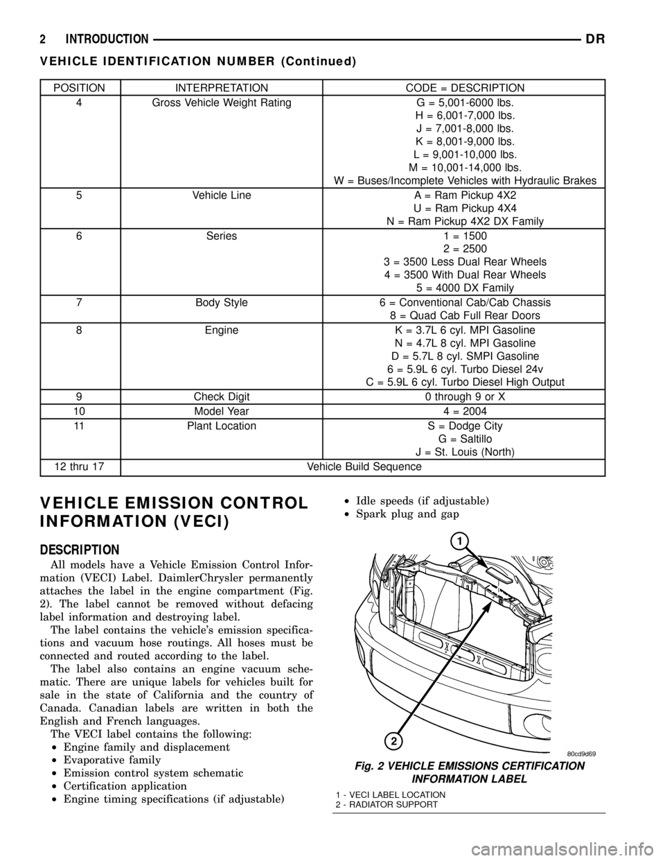
attaches the label in the engine compartment (Fig.
2). The label cannot be removed without defacing
label information and destroying label.
The label contains the vehicle's emission specifica-
tions and vacuum hose routings. All hoses must be
connected and routed according to the label.
The label also contains an engine vacuum sche-
matic. There are unique labels for vehicles built for
sale in the state of California and the country of
Canada. Canadian labels are written in both the
English and French languages.
The VECI label contains the following:
²Engine family and displacement
²Evaporative family
²Emission control system schematic
²Certification application
²Engine timing specifications (if adjustable)²Idle speeds (if adjustable)
²Spark plug and gap
Fig. 2 VEHICLE EMISSIONS CERTIFICATION
INFORMATION LABEL
1 - VECI LABEL LOCATION
2 - RADIATOR SUPPORT
2 INTRODUCTIONDR
VEHICLE IDENTIFICATION NUMBER (Continued)
Page 6 of 2627

INTERNATIONAL VEHICLE
CONTROL & DISPLAY
SYMBOLS
DESCRIPTION - INTERNATIONAL SYMBOLS
The graphic symbols illustrated in the following
International Control and Display Symbols Chart are
used to identify various instrument controls. The
symbols correspond to the controls and displays that
are located on the instrument panel.
FASTENER IDENTIFICATION
DESCRIPTION
The SAE bolt strength grades range from grade 2
to grade 8. The higher the grade number, the greater
the bolt strength. Identification is determined by the
line marks on the top of each bolt head. The actual
bolt strength grade corresponds to the number of line
marks plus 2. The most commonly used metric bolt
strength classes are 9.8 and 10.9. The metric
strength class identification number is imprinted on
the head of the bolt. The higher the class number,
the greater the bolt strength. Some metric nuts are
imprinted with a single-digit strength class on the
nut face. Refer to the Fastener Identification and
Fastener Strength Charts (Fig. 5) and (Fig. 6).
INTERNATIONAL SYMBOLS
1 High Beam 13 Rear Window Washer
2 Fog Lamps 14 Fuel
3 Headlamp, Parking Lamps, Panel Lamps 15 Engine Coolant Temperature
4 Turn Warning 16 Battery Charging Condition
5 Hazard Warning 17 Engine Oil
6 Windshield Washer 18 Seat Belt
7 Windshield Wiper 19 Brake Failure
8 Windshield Wiper and Washer 20 Parking Brake
9 Windscreen Demisting and Defrosting 21 Front Hood
10 Ventilating Fan 22 Rear hood (Decklid)
11 Rear Window Defogger 23 Horn
12 Rear Window Wiper 24 Lighter
DRINTRODUCTION 5
Page 39 of 2627

To adjust the vehicle height turn the torsion bar
adjustment bolt CLOCKWISE to raise the vehicle
and COUNTER CLOCKWISE to lower the vehicle.
CAUTION: ALWAYS raise the vehicle to the correct
suspension height, NEVER lower the vehicle to
obtain the correct suspension height. If the vehicle
suspension height is too high, lower the vehicle
below the height specification. Then raise the vehi-
cle to the correct suspension height specification.
This will insure the vehicle maintains the proper
suspension height.
NOTE: If a height adjustment has been made, per-
form height measurement again on both sides of
the vehicle.
STANDARD PROCEDURE - CAMBER AND
CASTER ADJUSTMENT
NOTE: 4X4 (LD) SUSPENSION HEIGHT MEASURE-
MENT MUST BE PERFORMED BEFORE AN ALIGN-
MENT.
NOTE: When the upper control arm pivot bolts are
loosened the upper control arm will normally go
inwards toward the frame automatically with the
weight of the vehicle.
Camber and caster angle adjustments involve
changing the position of the upper control arm incon-
junction with the slotted holes in the frame brackets,
Install special tool 8876 between the top of the upper
control arm bracket and the upper control arm (on
1500 series 4X2 & 4X4). Install special tool 8876
between the bottom of the upper control arm bracket
pressing the tool against the frame and the upper
control arm (on 2500/3500 series 4X2) in order to
move the upper control arm outwards for proper
adjustment with the vehicle at normal ride height
(Fig. 3).
STANDARD PROCEDURE - TOE ADJUSTMENT
4X4 SUSPENSION HEIGHT MESUREMENT
MUST BE PERFORMED BEFORE AN ALIGN-
MENT.
The wheel toe position adjustment is the final
adjustment.
(1) Start the engine and turn wheels both ways
before straightening the wheels. Secure the steering
wheel with the front wheels in the straight-ahead
position.
(2) Loosen the tie rod jam nuts.NOTE: Each front wheel should be adjusted for
one-half of the total toe position specification. This
will ensure the steering wheel will be centered
when the wheels are positioned straight-ahead.
(3) Adjust the wheel toe position by turning the
inner tie rod as necessary (Fig. 4).
(4) Tighten the tie rod jam nut to 75 N´m (55 ft.
lbs.).
(5) Verify the specifications
(6) Turn off engine.
STANDARD PROCEDURE - CAMBER, CASTER
AND TOE ADJUSTMENT
NOTE: 4X4 (LD) SUSPENSION HEIGHT MEASURE-
MENT MUST BE PERFORMED BEFORE AN ALIGN-
MENT.
Camber and caster angle adjustments involve
changing the position of the upper control arm with
the slots in the frame brackets using special tool
8876 to move the upper control arm outwards for
proper adjustment. (Fig. 3)
NOTE: When the upper control arm pivot bolts are
loosened the upper control arm will normally go
inwards toward the frame automatically with the
weight of the vehicle.
CASTER
Moving the front or rear position of the upper con-
trol arm in or out, will change the caster angle and
camber angle significantly. To maintain the camber
Fig. 3 CASTER & CAMBER ADJUSTMENT
1 - FRONT PIVOT BOLT
2 - REAR PIVOT BOLT
3 - SLOTTED HOLES FOR ADJUSTMENT OF CASTER &
CAMBER
4 - UPPER CONTROL ARM
2 - 4 WHEEL ALIGNMENTDR
WHEEL ALIGNMENT (Continued)
Page 40 of 2627

angle while adjusting caster, move one pivot bolt of
the upper control arm in or out. Then move the other
pivot bolt of the upper control arm in the opposite
direction. Install special tool 8876 between the top of
the upper control arm bracket and the upper control
arm (on 1500 series 4X2 & 4X4). Install special tool
8876 between the bottom of the upper control arm
bracket pressing the tool against the frame and the
upper control arm (on 2500/3500 series 4X2) in order
to move the upper control arm outwards for proper
adjustment with the vehicle at normal ride height
(Fig. 3).
To increase positive caster angle, move the rear
position of the upper control arm inward (toward the
engine). Move the front of the upper control arm out-
ward (away from the engine) slightly until the origi-
nal camber angle is obtained using special tool 8876
to move the upper control arm for proper adjustment.
(Fig. 3)
CAMBER
Move both pivot bolts of the upper control arm
together in or out. This will change the camber angle
significantly and little effect on the caster angle
using special tool 8876 to move the upper control
arm for proper adjustment. (Fig. 3)
After adjustment is made tighten the upper control
arm nuts to proper torque specification.
TOE ADJUSTMENT
The wheel toe position adjustment is the final
adjustment.
(1) Start the engine and turn wheels both ways
before straightening the wheels. Secure the steering
wheel with the front wheels in the straight-ahead
position.
(2) Loosen the tie rod jam nuts.
NOTE: Each front wheel should be adjusted for
one-half of the total toe position specification. This
will ensure the steering wheel will be centered
when the wheels are positioned straight-ahead.
(3) Adjust the wheel toe position by turning the
inner tie rod as necessary (Fig. 4).
(4) Tighten the tie rod jam nut to 75 N´m (55 ft.
lbs.).
(5) Verify the specifications
(6) Turn off engine.
STANDARD PROCEDURE - ALIGNMENT
LINK/COIL SUSPENSION
Before each alignment reading the vehicle should
be jounced (rear first, then front). Grasp each
bumper at the center and jounce the vehicle up and
down several times. Always release the bumper inthe down position.Set the front end alignment to
specifications while the vehicle is in its NOR-
MALLY LOADED CONDITION.
CAMBER:The wheel camber angle is preset and
is not adjustable.
CASTER:Check the caster of the front axle for
correct angle. Be sure the axle is not bent or twisted.
Road test the vehicle and make left and right turn.
Observe the steering wheel return-to-center position.
Low caster will cause poor steering wheel returnabil-
ity.
Caster can be adjusted by rotating the cams on the
lower suspension arm (Fig. 5).
TOE POSITION:The wheel toe position adjust-
ment should be the final adjustment.
Fig. 4 TIE ROD END
1 - JAM NUT
2 - TIE ROD - INNER
3 - TIE ROD END - OUTER
Fig. 5 ALIGNMENT ADJUSTMENT CAM
1 - BRACKET REINFORCEMENT
2 - ADJUSTING BOLT
3 - ADJUSTMENT CAM
DRWHEEL ALIGNMENT 2 - 5
WHEEL ALIGNMENT (Continued)
Page 320 of 2627

OPERATION
OPERATION - COOLING SYSTEM
The cooling system regulates engine operating tem-
perature. It allows the engine to reach normal oper-
ating temperature as quickly as possible. It also
maintains normal operating temperature and pre-
vents overheating.
The cooling system also provides a means of heat-
ing the passenger compartment and cooling the auto-
matic transmission fluid (if equipped). The cooling
system is pressurized and uses a centrifugal water
pump to circulate coolant throughout the system.
All engines utilize an ambient overflow bottle for
coolant recovery/reserve.
An optional factory installed maximum duty cool-
ing package is available on most models. This pack-
age will provide additional cooling capacity for
vehicles used under extreme conditions such as
trailer towing in high ambient temperatures.
OPERATION - HOSE CLAMPS
The spring type hose clamp applies constant ten-
sion on a hose connection. To remove a spring type
hose clamp, only use constant tension clamp pliers
designed to compress the hose clamp.
DIAGNOSIS AND TESTING
DIAGNOSIS AND TESTINGÐON-BOARD
DIAGNOSTICS (OBD)
COOLING SYSTEM RELATED DIAGNOSTICS
The Engine Control Module (ECM) has been pro-
grammed to monitor certain cooling system compo-
nents:
²If the engine has remained cool for too long a
period, such as with a stuck open thermostat, a Diag-
nostic Trouble Code (DTC) can be set.
²If an open or shorted condition has developed in
the electronically controlled viscous fan clutch circuit,
a Diagnostic Trouble Code (DTC) can be set.
²If fan speed is not detected a DTC will be set.
²Coolant temperature sensor circuit problems can
set a DTC.
If the problem is sensed in a monitored circuit
often enough to indicated an actual problem, a DTC
is stored. The DTC will be stored in the ECM mem-
ory for eventual display to the service technician.
(Refer to 25 - EMISSIONS CONTROL - DESCRIP-
TION).
ACCESSING DIAGNOSTIC TROUBLE CODES
To read DTC's and to obtain cooling system data,
(Refer to 25 - EMISSIONS CONTROL - DESCRIP-
TION).
ERASING TROUBLE CODES
After the problem has been repaired, use the
DRBIIItscan tool to erase a DTC. Refer to the
appropriate Powertrain Diagnostic Procedures ser-
vice information for operation of the DRBIIItscan
tool.
DIAGNOSIS AND TESTING - COOLING SYSTEM
- TESTING FOR LEAKS
ULTRAVIOLET LIGHT METHOD
A leak detection additive is available through the
parts department that can be added to cooling sys-
tem. The additive is highly visible under ultraviolet
light (black light). Pour one ounce of additive into
cooling system. Place heater control unit in HEAT
position. Start and operate the engine until the radi-
ator upper hose is warm to the touch. Aim the com-
mercially available black light tool at the components
to be checked. If leaks are present, the black light
will cause the additive to glow a bright green color.
The black light can be used in conjunction with a
pressure tester to determine if any external leaks
exist (Fig. 5).
Fig. 4 Spring Clamp Size Location
1 - SPRING CLAMP SIZE LOCATION
DRCOOLING 7 - 5
COOLING (Continued)
Page 322 of 2627
exhaust pipe may indicate a faulty cylinder head gas-
ket, cracked engine cylinder block or cylinder head.
A convenient check for exhaust gas leakage into
cooling system is provided by a commercially avail-
able Block Leak Check tool. Follow manufacturers
instructions when using this product.
COMBUSTION LEAKAGE TEST - WITHOUT
PRESSURE TESTER
DO NOT WASTE reusable coolant. If the solution
is clean, drain the coolant into a clean container for
reuse.
WARNING: DO NOT REMOVE CYLINDER BLOCK
DRAIN PLUGS OR LOOSEN RADIATOR DRAIN-
COCK WITH SYSTEM HOT AND UNDER PRESSURE.
SERIOUS BURNS FROM COOLANT CAN OCCUR.
Drain sufficient coolant to allow thermostat
removal. (Refer to 7 - COOLING/ENGINE/ENGINECOOLANT THERMOSTAT - REMOVAL). Remove
accessory drive belt (Refer to 7 - COOLING/ACCES-
SORY DRIVE/DRIVE BELTS - REMOVAL).
Add coolant to radiator to bring level to within 6.3
mm (1/4 in) of the top of the thermostat housing.
CAUTION: Avoid overheating. Do not operate
engine for an excessive period of time. Open drain-
cock immediately after test to eliminate boil over.
Start engine and accelerate rapidly three times, to
approximately 3000 rpm while observing coolant. If
internal engine combustion gases are leaking into
cooling system, bubbles will appear in coolant. If bub-
bles do not appear, internal combustion gas leakage
is not present.
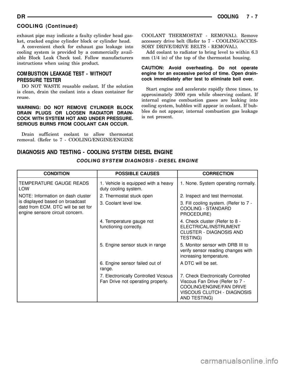
DIAGNOSIS AND TESTING - COOLING SYSTEM DIESEL ENGINE
COOLING SYSTEM DIAGNOSIS - DIESEL ENGINE
CONDITION POSSIBLE CAUSES CORRECTION
TEMPERATURE GAUGE READS
LOW1. Vehicle is equipped with a heavy
duty cooling system.1. None. System operating normally.
NOTE: Information on dash cluster
is displayed based on broadcast
datd from ECM. DTC will be set for
engine sensore circuit concern.2. Thermostat stuck open 2. Inspect and test thermostat.
3. Coolant level low. 3. Fill cooling system. (Refer to 7 -
COOLING - STANDARD
PROCEDURE)
4. Temperature gauge not
functioning correctly.4. Check cluster (Refer to 8 -
ELECTRICAL/INSTRUMENT
CLUSTER - DIAGNOSIS AND
TESTING)
5. Engine sensor stuck in range 5. Monitor sensor with DRB III to
verify sensor reading changes with
increasing temperature.
6. Engine sensor failed out of
range.A DTC will be set.
7. Electronically Controlled Vicsous
Fan Drive not operating properly.7. Check Electronically Controlled
Viscous Fan Drive (Refer to 7 -
COOLING/ENGINE/FAN DRIVE
VISCOUS CLUTCH - DIAGNOSIS
AND TESTING)
DRCOOLING 7 - 7
COOLING (Continued)
Page 323 of 2627
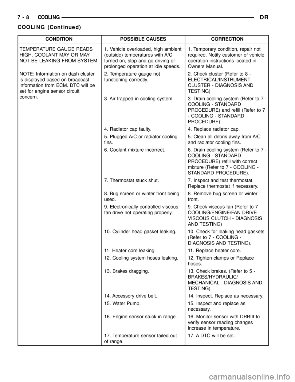
CONDITION POSSIBLE CAUSES CORRECTION
TEMPERATURE GAUGE READS
HIGH. COOLANT MAY OR MAY
NOT BE LEAKING FROM SYSTEM1. Vehicle overloaded, high ambient
(outside) temperatures with A/C
turned on, stop and go driving or
prolonged operation at idle speeds.1. Temporary condition, repair not
required. Notify customer of vehicle
operation instructions located in
Owners Manual.
NOTE: Information on dash cluster
is displayed based on broadcast
information from ECM. DTC will be
set for engine sensor circuit
concern.2. Temperature gauge not
functioning correctly.2. Check cluster (Refer to 8 -
ELECTRICAL/INSTRUMENT
CLUSTER - DIAGNOSIS AND
TESTING)
3. Air trapped in cooling system 3. Drain cooling system (Refer to 7 -
COOLING - STANDARD
PROCEDURE) and refill (Refer to 7
- COOLING - STANDARD
PROCEDURE)
4. Radiator cap faulty. 4. Replace radiator cap.
5. Plugged A/C or radiator cooling
fins.5. Clean all debris away from A/C
and radiator cooling fins.
6. Coolant mixture incorrect. 6. Drain cooling system (Refer to 7 -
COOLING - STANDARD
PROCEDURE) refill with correct
mixture (Refer to 7 - COOLING -
STANDARD PROCEDURE).
7. Thermostat stuck shut. 7. Inspect and test thermostat.
Replace thermostat if necessary.
8. Bug screen or winter front being
used.8. Remove bug screen or winter
front.
9. Electronically controlled viscous
fan drive not operating properly.9. Check viscous fan (Refer to 7 -
COOLING/ENGINE/FAN DRIVE
VISCOUS CLUTCH - DIAGNOSIS
AND TESTING)
10. Cylinder head gasket leaking. 10. Check for leaking head gaskets
(Refer to 7 - COOLING -
DIAGNOSIS AND TESTING).
11. Heater core leaking. 11. Replace heater core.
12. Cooling system hoses leaking. 12. Tighten clamps or Replace
hoses.
13. Brakes dragging. 13. Check brakes. (Refer to 5 -
BRAKES/HYDRAULIC/
MECHANICAL - DIAGNOSIS AND
TESTING)
14. Accessory drive belt. 14. Inspect. Replace as necessary.
15. Water Pump. 15. Inspect and replace as
necessary.
16. Engine sensor stuck in range. 16. Monitor sensor with DRBIII to
verify sensor reading changes
increase in temperature.
17. Temperature sensor failed out
of range.17. A DTC will be set.
7 - 8 COOLINGDR
COOLING (Continued)
Page 324 of 2627
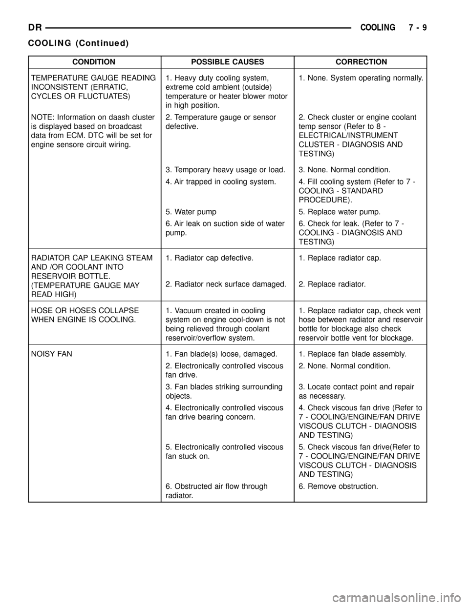
CONDITION POSSIBLE CAUSES CORRECTION
TEMPERATURE GAUGE READING
INCONSISTENT (ERRATIC,
CYCLES OR FLUCTUATES)1. Heavy duty cooling system,
extreme cold ambient (outside)
temperature or heater blower motor
in high position.1. None. System operating normally.
NOTE: Information on daash cluster
is displayed based on broadcast
data from ECM. DTC will be set for
engine sensore circuit wiring.2. Temperature gauge or sensor
defective.2. Check cluster or engine coolant
temp sensor (Refer to 8 -
ELECTRICAL/INSTRUMENT
CLUSTER - DIAGNOSIS AND
TESTING)
3. Temporary heavy usage or load. 3. None. Normal condition.
4. Air trapped in cooling system. 4. Fill cooling system (Refer to 7 -
COOLING - STANDARD
PROCEDURE).
5. Water pump 5. Replace water pump.
6. Air leak on suction side of water
pump.6. Check for leak. (Refer to 7 -
COOLING - DIAGNOSIS AND
TESTING)
RADIATOR CAP LEAKING STEAM
AND /OR COOLANT INTO
RESERVOIR BOTTLE.
(TEMPERATURE GAUGE MAY
READ HIGH)1. Radiator cap defective. 1. Replace radiator cap.
2. Radiator neck surface damaged. 2. Replace radiator.
HOSE OR HOSES COLLAPSE
WHEN ENGINE IS COOLING.1. Vacuum created in cooling
system on engine cool-down is not
being relieved through coolant
reservoir/overflow system.1. Replace radiator cap, check vent
hose between radiator and reservoir
bottle for blockage also check
reservoir bottle vent for blockage.
NOISY FAN 1. Fan blade(s) loose, damaged. 1. Replace fan blade assembly.
2. Electronically controlled viscous
fan drive.2. None. Normal condition.
3. Fan blades striking surrounding
objects.3. Locate contact point and repair
as necessary.
4. Electronically controlled viscous
fan drive bearing concern.4. Check viscous fan drive (Refer to
7 - COOLING/ENGINE/FAN DRIVE
VISCOUS CLUTCH - DIAGNOSIS
AND TESTING)
5. Electronically controlled viscous
fan stuck on.5. Check viscous fan drive(Refer to
7 - COOLING/ENGINE/FAN DRIVE
VISCOUS CLUTCH - DIAGNOSIS
AND TESTING)
6. Obstructed air flow through
radiator.6. Remove obstruction.
DRCOOLING 7 - 9
COOLING (Continued)
Page 325 of 2627
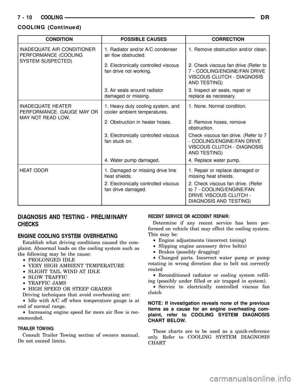
CONDITION POSSIBLE CAUSES CORRECTION
INADEQUATE AIR CONDITIONER
PERFORMANCE (COOLING
SYSTEM SUSPECTED)1. Radiator and/or A/C condenser
air flow obstructed.1. Remove obstruction and/or clean.
2. Electronically controlled viscous
fan drive not working.2. Check viscous fan drive (Refer to
7 - COOLING/ENGINE/FAN DRIVE
VISCOUS CLUTCH - DIAGNOSIS
AND TESTING)
3. Air seals around radiator
damaged or missing.3. Inspect air seals, repair or
replace as necessary.
INADEQUATE HEATER
PERFORMANCE. GAUGE MAY OR
MAY NOT READ LOW.1. Heavy duty cooling system, and
cooler ambient temperatures.1. None. Normal condition.
2. Obstruction in heater hoses. 2. Remove hoses, remove
obstruction.
3. Electronically controlled viscous
fan stuck on.Check viscous fan drive. (Refer to 7
- COOLING/ENGINE/FAN DRIVE
VISCOUS CLUTCH - DIAGNOSIS
AND TESTING)
4. Water pump damaged. 4. Replace water pump.
HEAT ODOR 1. Damaged or missing drive line
heat shields.1. Repair or replace damaged or
missing heat shields.
2. Electronically controlled viscous
fan drive damaged.2. Check viscous fan drive. (Refer
to 7 - COOLING/ENGINE/FAN
DRIVE VISCOUS CLUTCH -
DIAGNOSIS AND TESTING)
DIAGNOSIS AND TESTING - PRELIMINARY
CHECKS
ENGINE COOLING SYSTEM OVERHEATING
Establish what driving conditions caused the com-
plaint. Abnormal loads on the cooling system such as
the following may be the cause:
²PROLONGED IDLE
²VERY HIGH AMBIENT TEMPERATURE
²SLIGHT TAIL WIND AT IDLE
²SLOW TRAFFIC
²TRAFFIC JAMS
²HIGH SPEED OR STEEP GRADES
Driving techniques that avoid overheating are:
²Idle with A/C off when temperature gauge is at
end of normal range.
²Increasing engine speed for more air flow is rec-
ommended.
TRAILER TOWING:
Consult Trailer Towing section of owners manual.
Do not exceed limits.RECENT SERVICE OR ACCIDENT REPAIR:
Determine if any recent service has been per-
formed on vehicle that may effect the cooling system.
This may be:
²Engine adjustments (incorrect timing)
²Slipping engine accessory drive belt(s)
²Brakes (possibly dragging)
²Changed parts. Incorrect water pump or pump
rotating in wrong direction due to belt not correctly
routed
²Reconditioned radiator or cooling system refill-
ing (possibly under filled or air trapped in system).
²Service to electrically controlled viscous fan
clutch
NOTE: If investigation reveals none of the previous
items as a cause for an engine overheating com-
plaint, refer to COOLING SYSTEM DIAGNOSIS
CHART BELOW.
These charts are to be used as a quick-reference
only. Refer to COOLING SYSTEM DIAGNOSIS
CHART
7 - 10 COOLINGDR
COOLING (Continued)