Gauge DODGE RAM 1500 1998 2.G Workshop Manual
[x] Cancel search | Manufacturer: DODGE, Model Year: 1998, Model line: RAM 1500, Model: DODGE RAM 1500 1998 2.GPages: 2627
Page 114 of 2627
PINION GEAR DEPTH VARIANCE
Original Pinion
Gear Depth
VarianceNew Pinion Gear Depth Variance
24232221 0 +1 +2 +3 +4
+4+0.008 +0.007 +0.006 +0.005 +0.004 +0.003 +0.002 +0.001 0
+3+0.007 +0.006 +0.005 +0.004 +0.003 +0.002 +0.001 020.001
+2+0.006 +0.005 +0.004 +0.003 +0.002 +0.001 020.00120.002
+1+0.005 +0.004 +0.003 +0.002 +0.001 020.00120.00220.003
0+0.004 +0.003 +0.002 +0.001 020.00120.00220.00320.004
21+0.003 +0.002 +0.001 020.00120.00220.00320.00420.005
22+0.002 +0.001 020.00120.00220.00320.00420.00520.006
23+0.001 020.00120.00220.00320.00420.00520.00620.007
24020.00120.00220.00320.00420.00520.00620.00720.008
PINION DEPTH MEASUREMENT AND ADJUSTMENT
Measurements are taken with pinion cups and pin-
ion bearings installed in housing. Take measure-
ments with a Pinion Gauge Set, Pinion Block 8177,
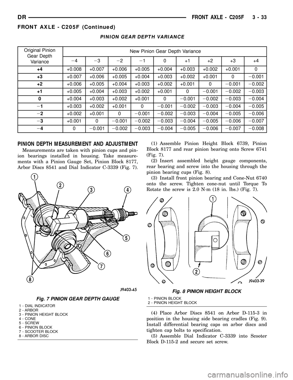
Arbor Discs 8541 and Dial Indicator C-3339 (Fig. 7).(1) Assemble Pinion Height Block 6739, Pinion
Block 8177 and rear pinion bearing onto Screw 6741
(Fig. 7).
(2) Insert assembled height gauge components,
rear bearing and screw into the housing through the
pinion bearing cups (Fig. 8).
(3) Install front pinion bearing and Cone-Nut 6740
onto the screw. Tighten cone-nut until Torque To
Rotate the screw is 2.0 N´m (18 in. lbs.) (Fig. 7).
(4) Place Arbor Discs 8541 on Arbor D-115-3 in
position in the housing side bearing cradles (Fig. 9).
Install differential bearing caps on arbor discs and
tighten cap bolts to specification.
(5) Assemble Dial Indicator C-3339 into Scooter
Block D-115-2 and secure set screw.
Fig. 7 PINION GEAR DEPTH GAUGE
1 - DIAL INDICATOR
2 - ARBOR
3 - PINION HEIGHT BLOCK
4 - CONE
5 - SCREW
6 - PINION BLOCK
7 - SCOOTER BLOCK
8 - ARBOR DISC
Fig. 8 PINION HEIGHT BLOCK
1 - PINION BLOCK
2 - PINION HEIGHT BLOCK
DRFRONT AXLE - C205F 3 - 33
FRONT AXLE - C205F (Continued)
Page 115 of 2627
(6) Place Scooter Block/Dial Indicator in position
in the housing so dial probe and scooter block are
flush against the surface of the pinion height block.
Hold scooter block in place and zero the dial indica-
tor. Tighten dial indicator face lock screw.
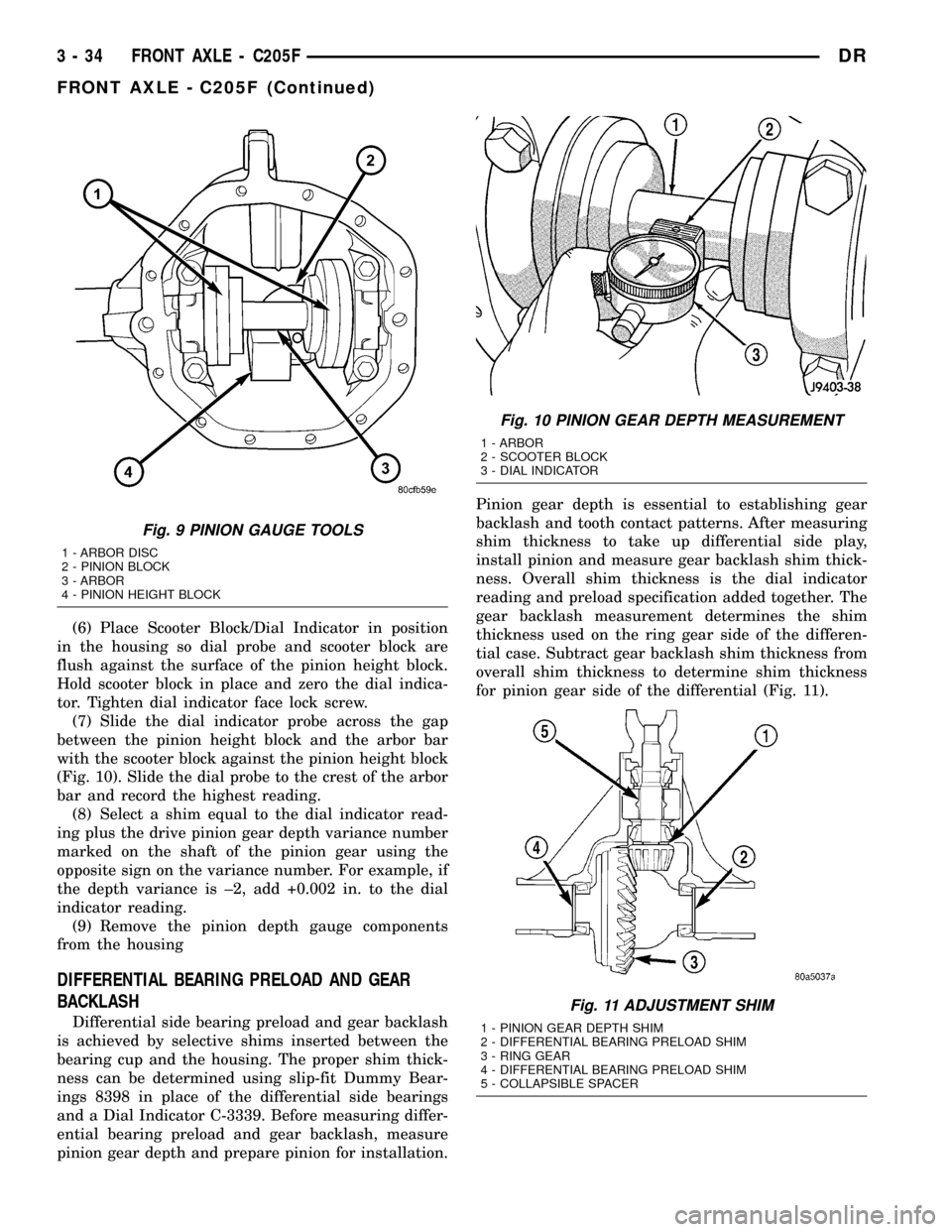
(7) Slide the dial indicator probe across the gap
between the pinion height block and the arbor bar
with the scooter block against the pinion height block
(Fig. 10). Slide the dial probe to the crest of the arbor
bar and record the highest reading.
(8) Select a shim equal to the dial indicator read-
ing plus the drive pinion gear depth variance number
marked on the shaft of the pinion gear using the
opposite sign on the variance number. For example, if
the depth variance is ±2, add +0.002 in. to the dial
indicator reading.
(9) Remove the pinion depth gauge components
from the housing
DIFFERENTIAL BEARING PRELOAD AND GEAR
BACKLASH
Differential side bearing preload and gear backlash
is achieved by selective shims inserted between the
bearing cup and the housing. The proper shim thick-
ness can be determined using slip-fit Dummy Bear-
ings 8398 in place of the differential side bearings
and a Dial Indicator C-3339. Before measuring differ-
ential bearing preload and gear backlash, measure
pinion gear depth and prepare pinion for installation.Pinion gear depth is essential to establishing gear
backlash and tooth contact patterns. After measuring
shim thickness to take up differential side play,
install pinion and measure gear backlash shim thick-
ness. Overall shim thickness is the dial indicator
reading and preload specification added together. The
gear backlash measurement determines the shim
thickness used on the ring gear side of the differen-
tial case. Subtract gear backlash shim thickness from
overall shim thickness to determine shim thickness
for pinion gear side of the differential (Fig. 11).
Fig. 9 PINION GAUGE TOOLS
1 - ARBOR DISC
2 - PINION BLOCK
3 - ARBOR
4 - PINION HEIGHT BLOCK
Fig. 10 PINION GEAR DEPTH MEASUREMENT
1 - ARBOR
2 - SCOOTER BLOCK
3 - DIAL INDICATOR
Fig. 11 ADJUSTMENT SHIM
1 - PINION GEAR DEPTH SHIM
2 - DIFFERENTIAL BEARING PRELOAD SHIM
3 - RING GEAR
4 - DIFFERENTIAL BEARING PRELOAD SHIM
5 - COLLAPSIBLE SPACER
3 - 34 FRONT AXLE - C205FDR
FRONT AXLE - C205F (Continued)
Page 140 of 2627
(7) Connect track bar to the axle bracket and
install the bolt. Do not tighten at this time.
(8) Install shock absorber and tighten bolts to 121
N´m (89 ft. lbs.).
(9) Install stabilizer bar link to the axle bracket.
Tighten the nut to 68 N´m (50 ft. lbs.).
(10) Install drag link and tie rod to the steering
knuckles and tighten the nuts to 108 N´m (80 ft.
lbs.).
(11) Install ABS wheel speed sensors.
(12) Install rotors and brake calipers.
(13) Connect the axle vent hose.
(14) Install front propeller shaft.
(15) With vehicle on the ground, tighten upper
suspension arm nuts at axle to 149 N´m (110 ft. lbs.).
Tighten upper suspension arm nuts at frame to 149
N´m (110 ft. lbs.).
(16) With vehicle on the ground, tighten lower sus-
pension arm nuts at axle to 190 N´m (140 ft. lbs.).
Tighten the lower suspension arm nuts at frame to
190 N´m (140 ft. lbs.).
(17) Tighten track bar bolt at the axle bracket to
176 N´m (130 ft. lbs.).
(18) Check front wheel alignment.
ADJUSTMENTS
Ring and pinion gears are supplied as matched
sets. Compensation for pinion depth variance is
achieved with a select shim. located between the rear
pinion bearing and pinion gear head.
PINION DEPTH MEASUREMENT AND ADJUSTMENT
Measurements are taken with pinion bearing cups
and pinion bearings installed in the housing. Take
measurements with Pinion Gauge Set and Dial Indi-
cator C-3339 (Fig. 6).
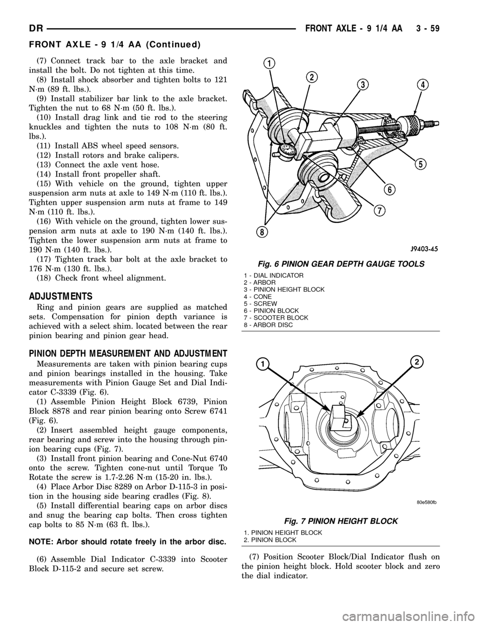
(1) Assemble Pinion Height Block 6739, Pinion
Block 8878 and rear pinion bearing onto Screw 6741
(Fig. 6).
(2) Insert assembled height gauge components,
rear bearing and screw into the housing through pin-
ion bearing cups (Fig. 7).
(3) Install front pinion bearing and Cone-Nut 6740
onto the screw. Tighten cone-nut until Torque To
Rotate the screw is 1.7-2.26 N´m (15-20 in. lbs.).
(4) Place Arbor Disc 8289 on Arbor D-115-3 in posi-
tion in the housing side bearing cradles (Fig. 8).
(5) Install differential bearing caps on arbor discs
and snug the bearing cap bolts. Then cross tighten
cap bolts to 85 N´m (63 ft. lbs.).
NOTE: Arbor should rotate freely in the arbor disc.
(6) Assemble Dial Indicator C-3339 into Scooter
Block D-115-2 and secure set screw.(7) Position Scooter Block/Dial Indicator flush on
the pinion height block. Hold scooter block and zero
the dial indicator.
Fig. 6 PINION GEAR DEPTH GAUGE TOOLS
1 - DIAL INDICATOR
2 - ARBOR
3 - PINION HEIGHT BLOCK
4 - CONE
5 - SCREW
6 - PINION BLOCK
7 - SCOOTER BLOCK
8 - ARBOR DISC
Fig. 7 PINION HEIGHT BLOCK
1. PINION HEIGHT BLOCK
2. PINION BLOCK
DRFRONT AXLE - 9 1/4 AA 3 - 59
FRONT AXLE - 9 1/4 AA (Continued)
Page 141 of 2627
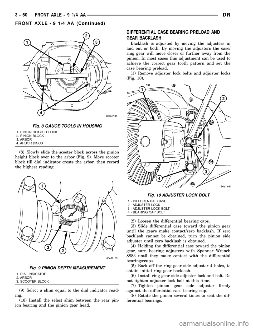
(8) Slowly slide the scooter block across the pinion
height block over to the arbor (Fig. 9). Move scooter
block till dial indicator crests the arbor, then record
the highest reading.
(9) Select a shim equal to the dial indicator read-
ing.
(10) Install the select shim between the rear pin-
ion bearing and the pinion gear head.
DIFFERENTIAL CASE BEARING PRELOAD AND
GEAR BACKLASH
Backlash is adjusted by moving the adjusters in
and out or both. By moving the adjusters the case/
ring gear will move closer or further away from the
pinion. In most cases this adjustment can be used to
achieve the correct gear tooth pattern and set the
case bearing preload.
(1) Remove adjuster lock bolts and adjuster locks
(Fig. 10).
(2) Loosen the differential bearing caps.
(3) Slide differential case toward the pinion gear
until the gears make contact/zero backlash. If zero
backlash cannot be obtained, turn the pinion side
adjuster until zero backlash is obtained.
(4) Holding the differential case toward the pinion
gear, turn bearing adjusters with Spanner Wrench
8883 until they make contact with the differential
bearings/cups.
(5) Back off the ring gear side adjuster 4 holes, to
obtain initial ring gear backlash.
(6) Install ring gear side adjuster lock and bolt. Do
not tighten adjuster lock bolt at this time.
(7) Tighten pinion gear side adjuster firmly
against the differential case bearing cup.
(8) Rotate the pinion several times to seat the dif-
ferential bearings.
Fig. 8 GAUGE TOOLS IN HOUSING
1. PINION HEIGHT BLOCK
2. PINION BLOCK
3. ARBOR
4. ARBOR DISCS
Fig. 9 PINION DEPTH MEASUREMENT
1. DIAL INDICATOR
2. ARBOR
3. SCOOTER BLOCK
Fig. 10 ADJUSTER LOCK BOLT
1 - DIFFERENTIAL CASE
2 - ADJUSTER LOCK
3 - ADJUSTER LOCK BOLT
4 - BEARING CAP BOLT
3 - 60 FRONT AXLE - 9 1/4 AADR
FRONT AXLE - 9 1/4 AA (Continued)
Page 166 of 2627
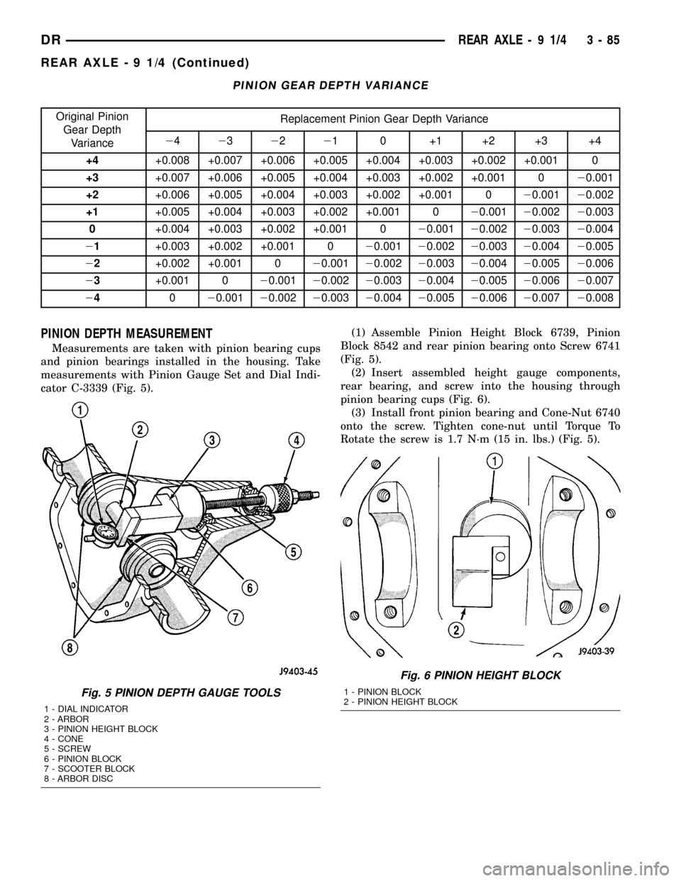
PINION GEAR DEPTH VARIANCE
Original Pinion
Gear Depth
VarianceReplacement Pinion Gear Depth Variance
24232221 0 +1 +2 +3 +4
+4+0.008 +0.007 +0.006 +0.005 +0.004 +0.003 +0.002 +0.001 0
+3+0.007 +0.006 +0.005 +0.004 +0.003 +0.002 +0.001 020.001
+2+0.006 +0.005 +0.004 +0.003 +0.002 +0.001 020.00120.002
+1+0.005 +0.004 +0.003 +0.002 +0.001 020.00120.00220.003
0+0.004 +0.003 +0.002 +0.001 020.00120.00220.00320.004
21+0.003 +0.002 +0.001 020.00120.00220.00320.00420.005
22+0.002 +0.001 020.00120.00220.00320.00420.00520.006
23+0.001 020.00120.00220.00320.00420.00520.00620.007
24020.00120.00220.00320.00420.00520.00620.00720.008
PINION DEPTH MEASUREMENT
Measurements are taken with pinion bearing cups
and pinion bearings installed in the housing. Take
measurements with Pinion Gauge Set and Dial Indi-
cator C-3339 (Fig. 5).(1) Assemble Pinion Height Block 6739, Pinion
Block 8542 and rear pinion bearing onto Screw 6741
(Fig. 5).
(2) Insert assembled height gauge components,
rear bearing, and screw into the housing through
pinion bearing cups (Fig. 6).
(3) Install front pinion bearing and Cone-Nut 6740
onto the screw. Tighten cone-nut until Torque To
Rotate the screw is 1.7 N´m (15 in. lbs.) (Fig. 5).
Fig. 5 PINION DEPTH GAUGE TOOLS
1 - DIAL INDICATOR
2 - ARBOR
3 - PINION HEIGHT BLOCK
4 - CONE
5 - SCREW
6 - PINION BLOCK
7 - SCOOTER BLOCK
8 - ARBOR DISC
Fig. 6 PINION HEIGHT BLOCK
1 - PINION BLOCK
2 - PINION HEIGHT BLOCK
DRREAR AXLE - 9 1/4 3 - 85
REAR AXLE - 9 1/4 (Continued)
Page 170 of 2627

SIDE GEAR CLEARANCE
When measuring side gear clearance, check each
gear independently. If it necessary to replace a side
gear, replace both gears as a matched set.
(1) Install the axle shafts and C-locks and pinion
mate shaft.
(2) Measure each side gear clearance. Insert a
matched pair of feeler gauge blades between the gear
and differential housing on opposite sides of the hub
(Fig. 17).(3) If side gear clearances is no more than 0.005
inch. Determine if the axle shaft is contacting the
pinion mate shaft.Do not remove the feeler
gauges, inspect the axle shaft with the feeler
gauge inserted behind the side gear.If the end of
the axle shaft is not contacting the pinion mate
shaft, the side gear clearance is acceptable.
(4) If clearance is more than 0.005 inch (axle shaft
not contacting mate shaft), record the side gear clear-
ance. Remove the thrust washer and measure its
thickness with a micrometer. Add the washer thick-
ness to the recorded side gear clearance. The sum of
gear clearance and washer thickness will determine
required thickness of replacement thrust washer
(Fig. 18).
In some cases, the end of the axle shaft will move
and contact the mate shaft when the feeler gauge is
inserted. The C-lock is preventing the side gear from
sliding on the axle shaft.
(5) If there is no side gear clearance, remove the
C-lock from the axle shaft. Use a micrometer to mea-
sure the thrust washer thickness. Record the thick-
ness and re-install the thrust washer. Assemble the
differential case without the C-lock installed and re-
measure the side gear clearance.
(6) Compare both clearance measurements. If the
difference is less than 0.012 inch (0.305 mm), add
clearance recorded when the C-lock was installed to
thrust washer thickness measured. The sum will
determine the required thickness of the replacement
thrust washer.
(7) If clearance is 0.012 inch (0.305 mm) or
greater, both side gears must be replaced (matched
set) and the clearance measurements repeated.
(8) If clearance (above) continues to be 0.012 inch
(0.305 mm) or greater, the case must be replaced.
Fig. 16 HIGH PINION HEIGHT
Fig. 17 SIDE GEAR CLEARANCE
1 - FEELER GAUGE
2 - SIDE GEAR
Fig. 18 SIDE GEAR CALCULATIONS
DRREAR AXLE - 9 1/4 3 - 89
REAR AXLE - 9 1/4 (Continued)
Page 173 of 2627

INSTALLER C-4308
INSTALLER C-4345
TRAC-LOK TOOLS C-4487
PULLER C-452
HANDLE C-4735
INSTALLER D-130
REMOVER 6310
HOLDER 6719A
PINION GAUGE SET 6730/6774/6775
TRAC-LOK TORQUE FIXTURE 6790
3 - 92 REAR AXLE-91/4DR
REAR AXLE - 9 1/4 (Continued)
Page 183 of 2627
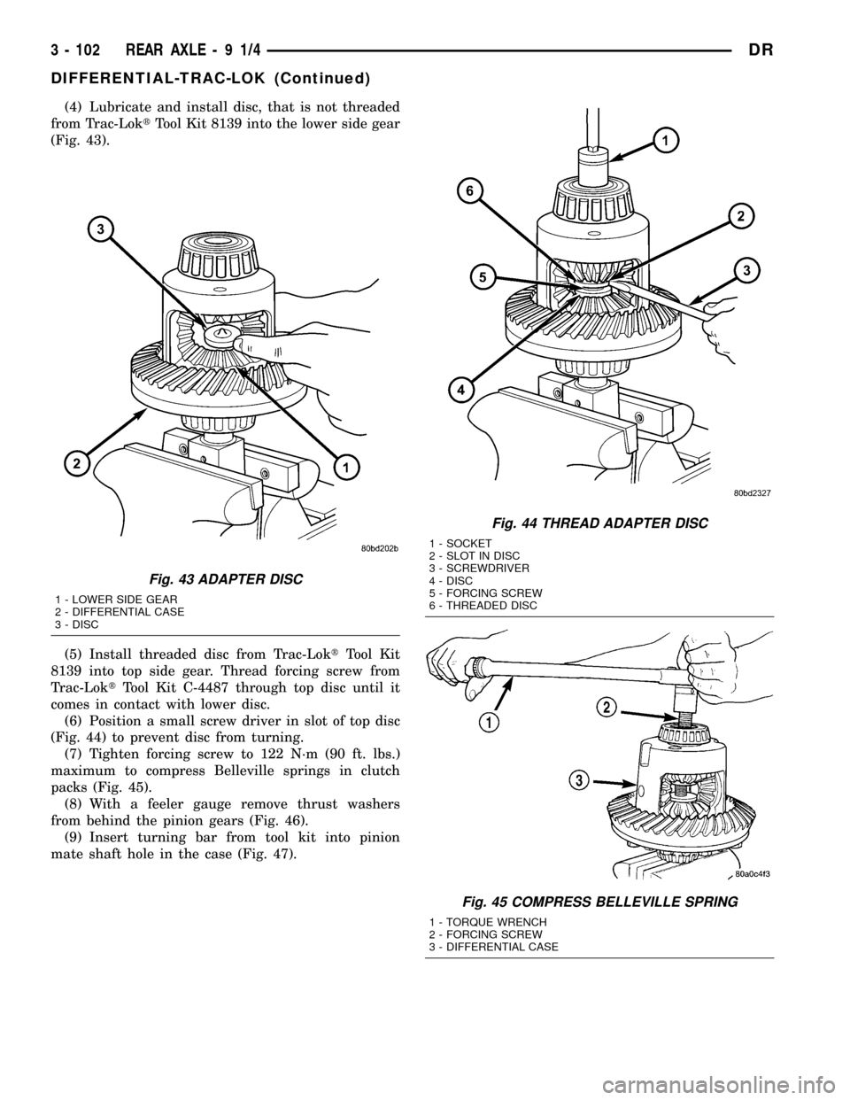
(4) Lubricate and install disc, that is not threaded
from Trac-LoktTool Kit 8139 into the lower side gear
(Fig. 43).
(5) Install threaded disc from Trac-LoktTool Kit
8139 into top side gear. Thread forcing screw from
Trac-LoktTool Kit C-4487 through top disc until it
comes in contact with lower disc.
(6) Position a small screw driver in slot of top disc
(Fig. 44) to prevent disc from turning.
(7) Tighten forcing screw to 122 N´m (90 ft. lbs.)
maximum to compress Belleville springs in clutch
packs (Fig. 45).
(8) With a feeler gauge remove thrust washers
from behind the pinion gears (Fig. 46).
(9) Insert turning bar from tool kit into pinion
mate shaft hole in the case (Fig. 47).
Fig. 43 ADAPTER DISC
1 - LOWER SIDE GEAR
2 - DIFFERENTIAL CASE
3 - DISC
Fig. 44 THREAD ADAPTER DISC
1 - SOCKET
2 - SLOT IN DISC
3 - SCREWDRIVER
4 - DISC
5 - FORCING SCREW
6 - THREADED DISC
Fig. 45 COMPRESS BELLEVILLE SPRING
1 - TORQUE WRENCH
2 - FORCING SCREW
3 - DIFFERENTIAL CASE
3 - 102 REAR AXLE-91/4DR
DIFFERENTIAL-TRAC-LOK (Continued)
Page 184 of 2627
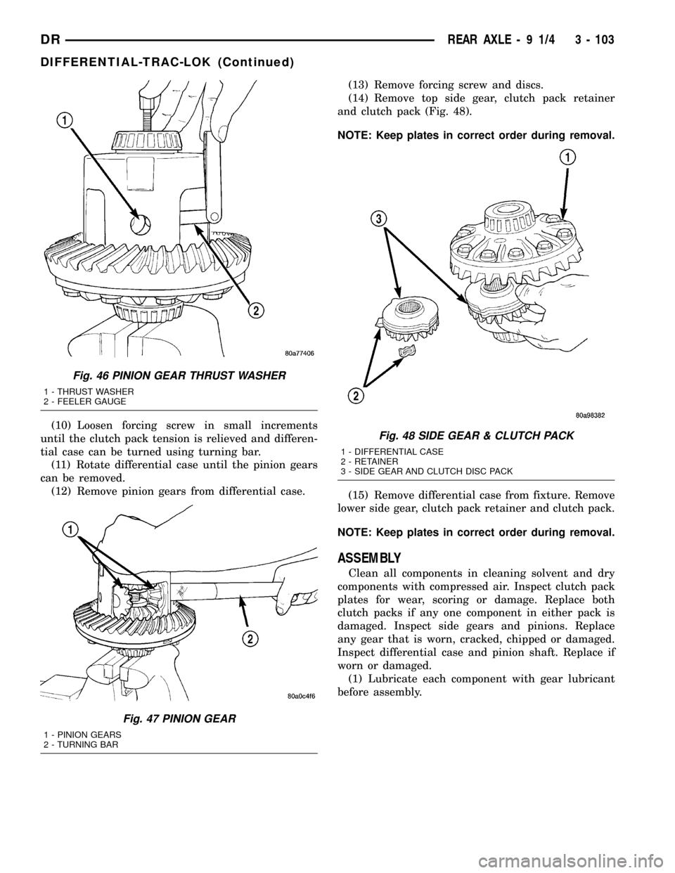
(10) Loosen forcing screw in small increments
until the clutch pack tension is relieved and differen-
tial case can be turned using turning bar.
(11) Rotate differential case until the pinion gears
can be removed.
(12) Remove pinion gears from differential case.(13) Remove forcing screw and discs.
(14) Remove top side gear, clutch pack retainer
and clutch pack (Fig. 48).
NOTE: Keep plates in correct order during removal.
(15) Remove differential case from fixture. Remove
lower side gear, clutch pack retainer and clutch pack.
NOTE: Keep plates in correct order during removal.
ASSEMBLY
Clean all components in cleaning solvent and dry
components with compressed air. Inspect clutch pack
plates for wear, scoring or damage. Replace both
clutch packs if any one component in either pack is
damaged. Inspect side gears and pinions. Replace
any gear that is worn, cracked, chipped or damaged.
Inspect differential case and pinion shaft. Replace if
worn or damaged.
(1) Lubricate each component with gear lubricant
before assembly.
Fig. 46 PINION GEAR THRUST WASHER
1 - THRUST WASHER
2 - FEELER GAUGE
Fig. 47 PINION GEAR
1 - PINION GEARS
2 - TURNING BAR
Fig. 48 SIDE GEAR & CLUTCH PACK
1 - DIFFERENTIAL CASE
2 - RETAINER
3 - SIDE GEAR AND CLUTCH DISC PACK
DRREAR AXLE - 9 1/4 3 - 103
DIFFERENTIAL-TRAC-LOK (Continued)
Page 197 of 2627
INSTALLATION
(1) Raise axle with lift and align to the leaf spring
centering bolts.
(2) Install axle U-bolts and tighten to 149 N´m
(110 ft. lbs.).
(3) Install shock absorbers to axle and tighten to
specification.
(4) Install all brake components.
(5) Align propeller shaft and pinion companion
flange reference marks and tighten companion flange
bolts to 115 N´m (85 ft. lbs.).
(6) Install the wheels and tires.
(7) Fill differential to specifications.
(8) Remove lift from axle and lower the vehicle.
ADJUSTMENTS
Ring and pinion gears are supplied as matched
sets. Compensation for pinion depth variance is
achieved with a select shim. The shim is located
between the rear pinion bearing and the pinion gear
head.
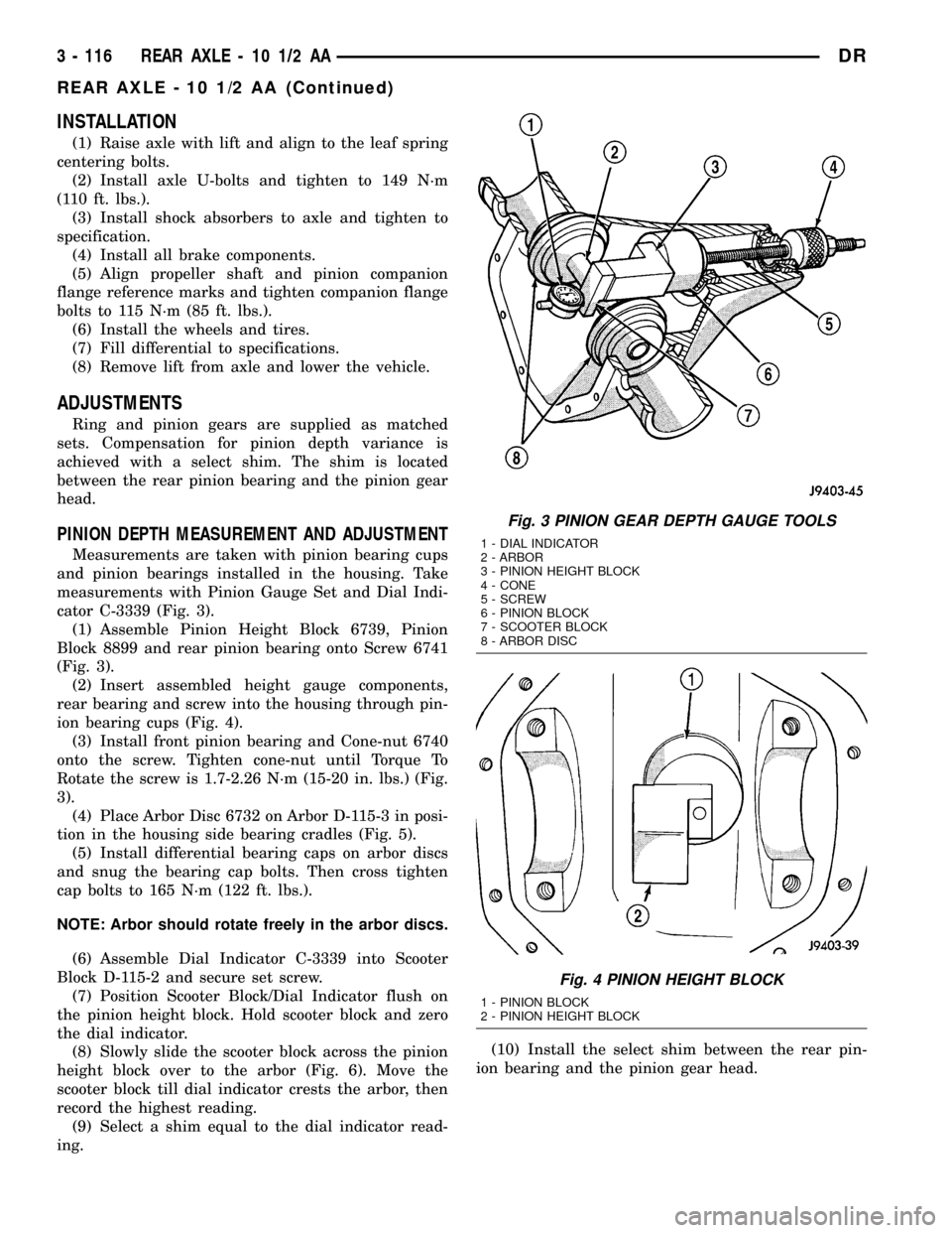
PINION DEPTH MEASUREMENT AND ADJUSTMENT
Measurements are taken with pinion bearing cups
and pinion bearings installed in the housing. Take
measurements with Pinion Gauge Set and Dial Indi-
cator C-3339 (Fig. 3).
(1) Assemble Pinion Height Block 6739, Pinion
Block 8899 and rear pinion bearing onto Screw 6741
(Fig. 3).
(2) Insert assembled height gauge components,
rear bearing and screw into the housing through pin-
ion bearing cups (Fig. 4).
(3) Install front pinion bearing and Cone-nut 6740
onto the screw. Tighten cone-nut until Torque To
Rotate the screw is 1.7-2.26 N´m (15-20 in. lbs.) (Fig.
3).
(4) Place Arbor Disc 6732 on Arbor D-115-3 in posi-
tion in the housing side bearing cradles (Fig. 5).
(5) Install differential bearing caps on arbor discs
and snug the bearing cap bolts. Then cross tighten
cap bolts to 165 N´m (122 ft. lbs.).
NOTE: Arbor should rotate freely in the arbor discs.
(6) Assemble Dial Indicator C-3339 into Scooter
Block D-115-2 and secure set screw.
(7) Position Scooter Block/Dial Indicator flush on
the pinion height block. Hold scooter block and zero
the dial indicator.
(8) Slowly slide the scooter block across the pinion
height block over to the arbor (Fig. 6). Move the
scooter block till dial indicator crests the arbor, then
record the highest reading.
(9) Select a shim equal to the dial indicator read-
ing.(10) Install the select shim between the rear pin-
ion bearing and the pinion gear head.
Fig. 3 PINION GEAR DEPTH GAUGE TOOLS
1 - DIAL INDICATOR
2 - ARBOR
3 - PINION HEIGHT BLOCK
4 - CONE
5 - SCREW
6 - PINION BLOCK
7 - SCOOTER BLOCK
8 - ARBOR DISC
Fig. 4 PINION HEIGHT BLOCK
1 - PINION BLOCK
2 - PINION HEIGHT BLOCK
3 - 116 REAR AXLE - 10 1/2 AADR
REAR AXLE - 10 1/2 AA (Continued)