banjo DODGE RAM 1500 1998 2.G Workshop Manual
[x] Cancel search | Manufacturer: DODGE, Model Year: 1998, Model line: RAM 1500, Model: DODGE RAM 1500 1998 2.GPages: 2627
Page 257 of 2627
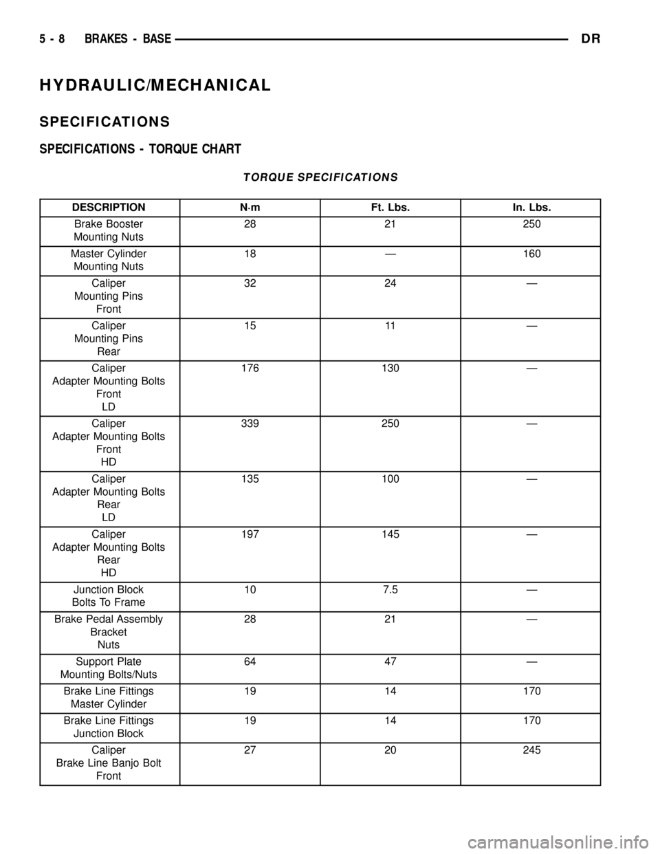
HYDRAULIC/MECHANICAL
SPECIFICATIONS
SPECIFICATIONS - TORQUE CHART
TORQUE SPECIFICATIONS
DESCRIPTION N´m Ft. Lbs. In. Lbs.
Brake Booster
Mounting Nuts28 21 250
Master Cylinder
Mounting Nuts18 Ð 160
Caliper
Mounting Pins
Front32 24 Ð
Caliper
Mounting Pins
Rear15 11 Ð
Caliper
Adapter Mounting Bolts
Front
LD176 130 Ð
Caliper
Adapter Mounting Bolts
Front
HD339 250 Ð
Caliper
Adapter Mounting Bolts
Rear
LD135 100 Ð
Caliper
Adapter Mounting Bolts
Rear
HD197 145 Ð
Junction Block
Bolts To Frame10 7.5 Ð
Brake Pedal Assembly
Bracket
Nuts28 21 Ð
Support Plate
Mounting Bolts/Nuts64 47 Ð
Brake Line Fittings
Master Cylinder19 14 170
Brake Line Fittings
Junction Block19 14 170
Caliper
Brake Line Banjo Bolt
Front27 20 245
5 - 8 BRAKES - BASEDR
Page 258 of 2627
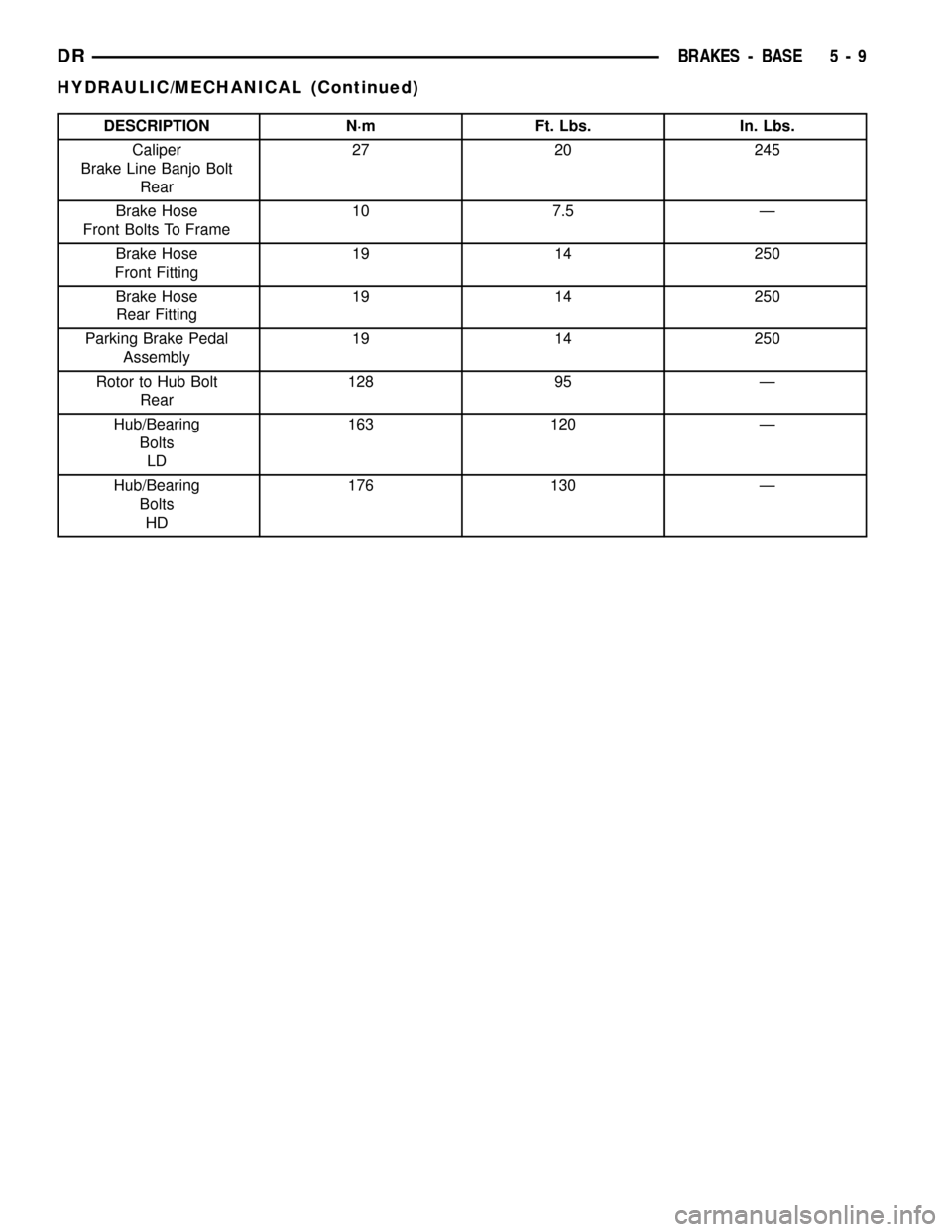
DESCRIPTION N´m Ft. Lbs. In. Lbs.
Caliper
Brake Line Banjo Bolt
Rear27 20 245
Brake Hose
Front Bolts To Frame10 7.5 Ð
Brake Hose
Front Fitting19 14 250
Brake Hose
Rear Fitting19 14 250
Parking Brake Pedal
Assembly19 14 250
Rotor to Hub Bolt
Rear128 95 Ð
Hub/Bearing
Bolts
LD163 120 Ð
Hub/Bearing
Bolts
HD176 130 Ð
DRBRAKES - BASE 5 - 9
HYDRAULIC/MECHANICAL (Continued)
Page 261 of 2627
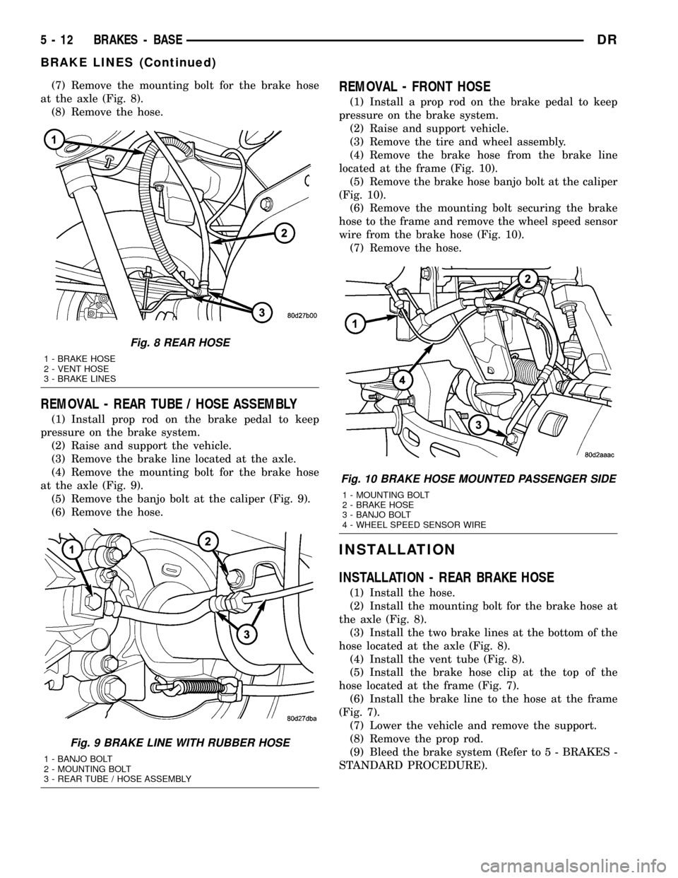
(7) Remove the mounting bolt for the brake hose
at the axle (Fig. 8).
(8) Remove the hose.
REMOVAL - REAR TUBE / HOSE ASSEMBLY
(1) Install prop rod on the brake pedal to keep
pressure on the brake system.
(2) Raise and support the vehicle.
(3) Remove the brake line located at the axle.
(4) Remove the mounting bolt for the brake hose
at the axle (Fig. 9).
(5) Remove the banjo bolt at the caliper (Fig. 9).
(6) Remove the hose.
REMOVAL - FRONT HOSE
(1) Install a prop rod on the brake pedal to keep
pressure on the brake system.
(2) Raise and support vehicle.
(3) Remove the tire and wheel assembly.
(4) Remove the brake hose from the brake line
located at the frame (Fig. 10).
(5) Remove the brake hose banjo bolt at the caliper
(Fig. 10).
(6) Remove the mounting bolt securing the brake
hose to the frame and remove the wheel speed sensor
wire from the brake hose (Fig. 10).
(7) Remove the hose.
INSTALLATION
INSTALLATION - REAR BRAKE HOSE
(1) Install the hose.
(2) Install the mounting bolt for the brake hose at
the axle (Fig. 8).
(3) Install the two brake lines at the bottom of the
hose located at the axle (Fig. 8).
(4) Install the vent tube (Fig. 8).
(5) Install the brake hose clip at the top of the
hose located at the frame (Fig. 7).
(6) Install the brake line to the hose at the frame
(Fig. 7).
(7) Lower the vehicle and remove the support.
(8) Remove the prop rod.
(9) Bleed the brake system (Refer to 5 - BRAKES -
STANDARD PROCEDURE).
Fig. 8 REAR HOSE
1 - BRAKE HOSE
2 - VENT HOSE
3 - BRAKE LINES
Fig. 9 BRAKE LINE WITH RUBBER HOSE
1 - BANJO BOLT
2 - MOUNTING BOLT
3 - REAR TUBE / HOSE ASSEMBLY
Fig. 10 BRAKE HOSE MOUNTED PASSENGER SIDE
1 - MOUNTING BOLT
2 - BRAKE HOSE
3 - BANJO BOLT
4 - WHEEL SPEED SENSOR WIRE
5 - 12 BRAKES - BASEDR
BRAKE LINES (Continued)
Page 262 of 2627
INSTALLATION - REAR TUBE / HOSE
ASSEMBLY
(1) Install the hose.
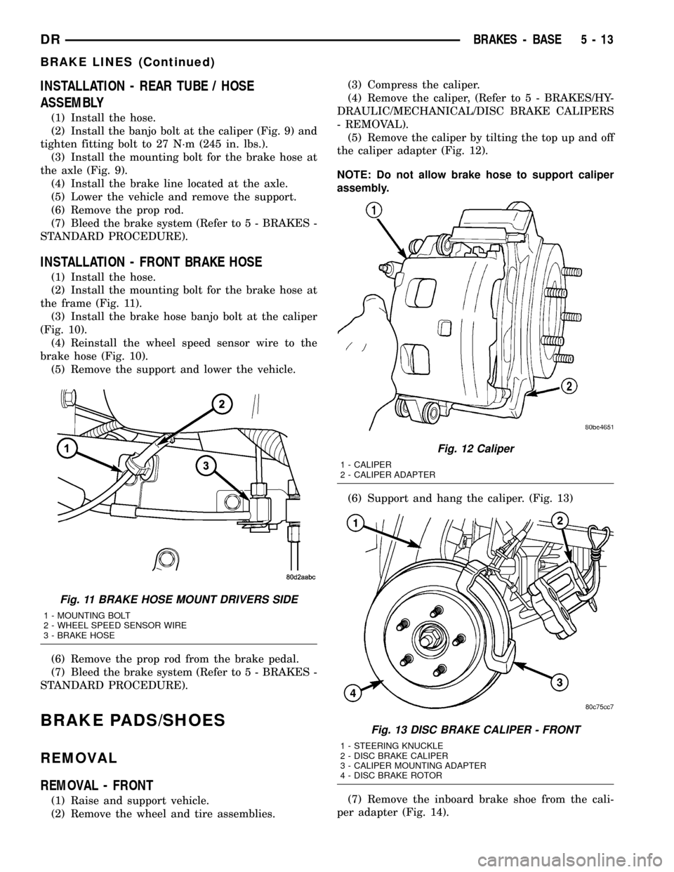
(2) Install the banjo bolt at the caliper (Fig. 9) and
tighten fitting bolt to 27 N´m (245 in. lbs.).
(3) Install the mounting bolt for the brake hose at
the axle (Fig. 9).
(4) Install the brake line located at the axle.
(5) Lower the vehicle and remove the support.
(6) Remove the prop rod.
(7) Bleed the brake system (Refer to 5 - BRAKES -
STANDARD PROCEDURE).
INSTALLATION - FRONT BRAKE HOSE
(1) Install the hose.
(2) Install the mounting bolt for the brake hose at
the frame (Fig. 11).
(3) Install the brake hose banjo bolt at the caliper
(Fig. 10).
(4) Reinstall the wheel speed sensor wire to the
brake hose (Fig. 10).
(5) Remove the support and lower the vehicle.
(6) Remove the prop rod from the brake pedal.
(7) Bleed the brake system (Refer to 5 - BRAKES -
STANDARD PROCEDURE).
BRAKE PADS/SHOES
REMOVAL
REMOVAL - FRONT
(1) Raise and support vehicle.
(2) Remove the wheel and tire assemblies.(3) Compress the caliper.
(4) Remove the caliper, (Refer to 5 - BRAKES/HY-
DRAULIC/MECHANICAL/DISC BRAKE CALIPERS
- REMOVAL).
(5) Remove the caliper by tilting the top up and off
the caliper adapter (Fig. 12).
NOTE: Do not allow brake hose to support caliper
assembly.
(6) Support and hang the caliper. (Fig. 13)
(7) Remove the inboard brake shoe from the cali-
per adapter (Fig. 14).
Fig. 11 BRAKE HOSE MOUNT DRIVERS SIDE
1 - MOUNTING BOLT
2 - WHEEL SPEED SENSOR WIRE
3 - BRAKE HOSE
Fig. 12 Caliper
1 - CALIPER
2 - CALIPER ADAPTER
Fig. 13 DISC BRAKE CALIPER - FRONT
1 - STEERING KNUCKLE
2 - DISC BRAKE CALIPER
3 - CALIPER MOUNTING ADAPTER
4 - DISC BRAKE ROTOR
DRBRAKES - BASE 5 - 13
BRAKE LINES (Continued)
Page 266 of 2627
rotor. At the same time, fluid pressure within the pis-
ton bore forces the caliper to slide inward on the
mounting bolts. This action brings the outboard
brake pad lining into contact with the outer surface
of the disc brake rotor.
In summary, fluid pressure acting simultaneously
on both piston and caliper, produces a strong clamp-
ing action. When sufficient force is applied, friction
will attempt to stop the rotors from turning and
bring the vehicle to a stop.
Application and release of the brake pedal gener-
ates only a very slight movement of the caliper and
piston. Upon release of the pedal, the caliper and pis-
ton return to a rest position. The brake pads do not
retract an appreciable distance from the rotor. In
fact, clearance is usually at, or close to zero. The rea-
sons for this are to keep road debris from getting
between the rotor and lining and in wiping the rotor
surface clear each revolution.
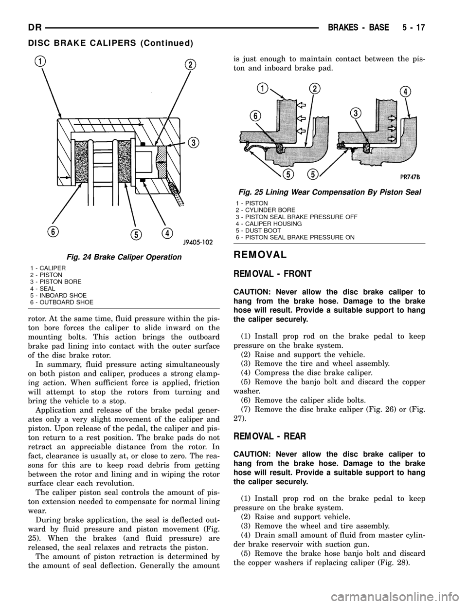
The caliper piston seal controls the amount of pis-
ton extension needed to compensate for normal lining
wear.
During brake application, the seal is deflected out-
ward by fluid pressure and piston movement (Fig.
25). When the brakes (and fluid pressure) are
released, the seal relaxes and retracts the piston.
The amount of piston retraction is determined by
the amount of seal deflection. Generally the amountis just enough to maintain contact between the pis-
ton and inboard brake pad.
REMOVAL
REMOVAL - FRONT
CAUTION: Never allow the disc brake caliper to
hang from the brake hose. Damage to the brake
hose will result. Provide a suitable support to hang
the caliper securely.
(1) Install prop rod on the brake pedal to keep
pressure on the brake system.
(2) Raise and support the vehicle.
(3) Remove the tire and wheel assembly.
(4) Compress the disc brake caliper.
(5) Remove the banjo bolt and discard the copper
washer.
(6) Remove the caliper slide bolts.
(7) Remove the disc brake caliper (Fig. 26) or (Fig.
27).
REMOVAL - REAR
CAUTION: Never allow the disc brake caliper to
hang from the brake hose. Damage to the brake
hose will result. Provide a suitable support to hang
the caliper securely.
(1) Install prop rod on the brake pedal to keep
pressure on the brake system.
(2) Raise and support vehicle.
(3) Remove the wheel and tire assembly.
(4) Drain small amount of fluid from master cylin-
der brake reservoir with suction gun.
(5) Remove the brake hose banjo bolt and discard
the copper washers if replacing caliper (Fig. 28).
Fig. 24 Brake Caliper Operation
1 - CALIPER
2 - PISTON
3 - PISTON BORE
4 - SEAL
5 - INBOARD SHOE
6 - OUTBOARD SHOE
Fig. 25 Lining Wear Compensation By Piston Seal
1 - PISTON
2 - CYLINDER BORE
3 - PISTON SEAL BRAKE PRESSURE OFF
4 - CALIPER HOUSING
5 - DUST BOOT
6 - PISTON SEAL BRAKE PRESSURE ON
DRBRAKES - BASE 5 - 17
DISC BRAKE CALIPERS (Continued)
Page 267 of 2627
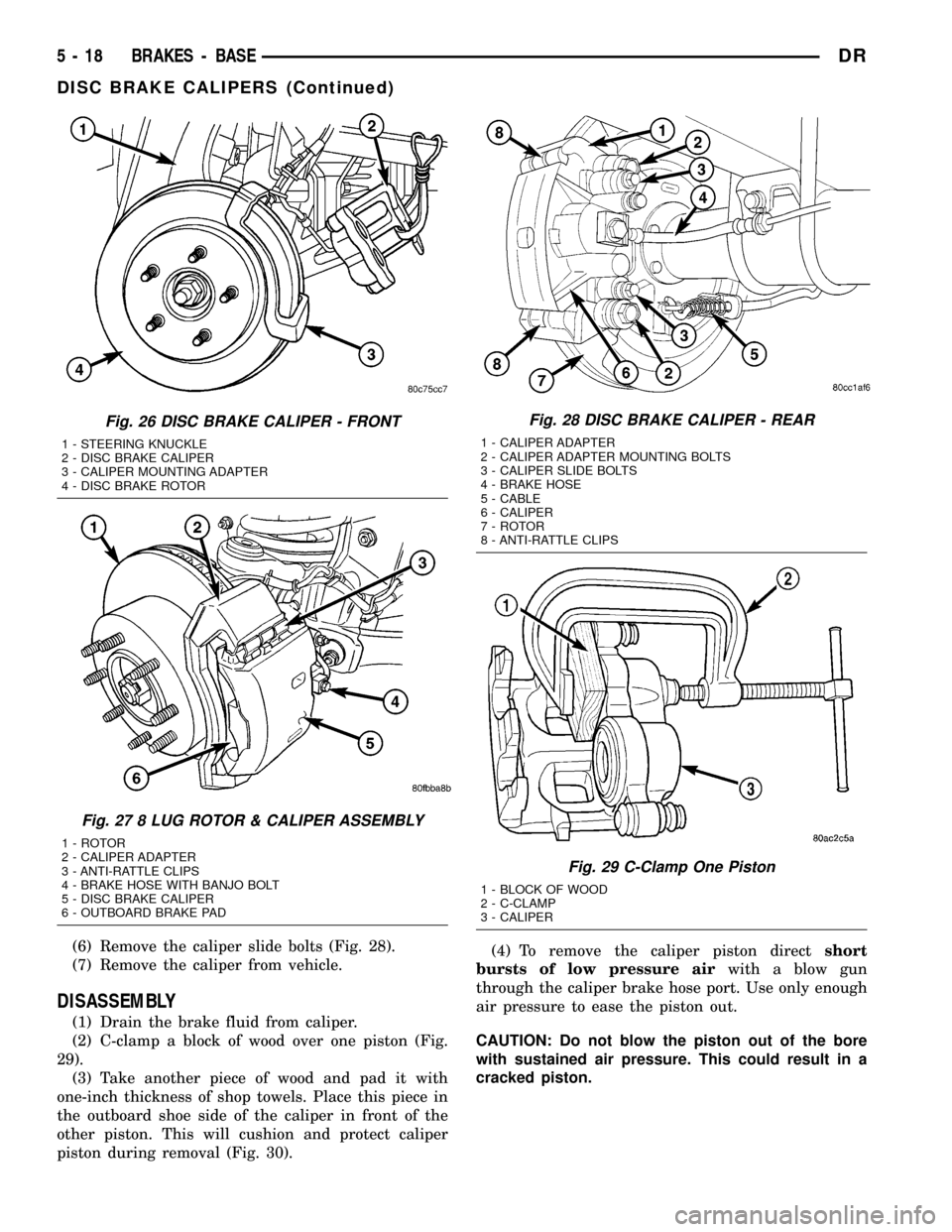
(6) Remove the caliper slide bolts (Fig. 28).
(7) Remove the caliper from vehicle.
DISASSEMBLY
(1) Drain the brake fluid from caliper.
(2) C-clamp a block of wood over one piston (Fig.
29).
(3) Take another piece of wood and pad it with
one-inch thickness of shop towels. Place this piece in
the outboard shoe side of the caliper in front of the
other piston. This will cushion and protect caliper
piston during removal (Fig. 30).(4) To remove the caliper piston directshort
bursts of low pressure airwith a blow gun
through the caliper brake hose port. Use only enough
air pressure to ease the piston out.
CAUTION: Do not blow the piston out of the bore
with sustained air pressure. This could result in a
cracked piston.
Fig. 26 DISC BRAKE CALIPER - FRONT
1 - STEERING KNUCKLE
2 - DISC BRAKE CALIPER
3 - CALIPER MOUNTING ADAPTER
4 - DISC BRAKE ROTOR
Fig. 27 8 LUG ROTOR & CALIPER ASSEMBLY
1 - ROTOR
2 - CALIPER ADAPTER
3 - ANTI-RATTLE CLIPS
4 - BRAKE HOSE WITH BANJO BOLT
5 - DISC BRAKE CALIPER
6 - OUTBOARD BRAKE PAD
Fig. 28 DISC BRAKE CALIPER - REAR
1 - CALIPER ADAPTER
2 - CALIPER ADAPTER MOUNTING BOLTS
3 - CALIPER SLIDE BOLTS
4 - BRAKE HOSE
5 - CABLE
6 - CALIPER
7 - ROTOR
8 - ANTI-RATTLE CLIPS
Fig. 29 C-Clamp One Piston
1 - BLOCK OF WOOD
2 - C-CLAMP
3 - CALIPER
5 - 18 BRAKES - BASEDR
DISC BRAKE CALIPERS (Continued)
Page 270 of 2627
INSTALLATION
INSTALLATION - FRONT
NOTE: Install a new copper washers on the banjo
bolt when installing
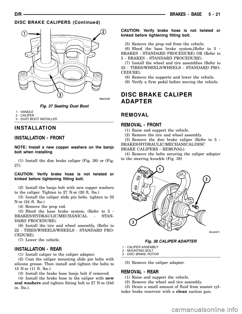
(1) Install the disc brake caliper (Fig. 26) or (Fig.
27).
CAUTION: Verify brake hose is not twisted or
kinked before tightening fitting bolt.
(2) Install the banjo bolt with new copper washers
to the caliper. Tighten to 27 N´m (20 ft. lbs.)
(3) Install the caliper slide pin bolts. tighten to 32
N´m (24 ft. lbs.)
(4) Remove the prop rod.
(5) Bleed the base brake system, (Refer to 5 -
BRAKES/HYDRAULIC/MECHANICAL - STAN-
DARD PROCEDURE).
(6) Install the tire and wheel assembly, (Refer to
22 - TIRES/WHEELS/WHEELS - STANDARD PRO-
CEDURE).
(7) Lower the vehicle.
INSTALLATION - REAR
(1) Install caliper to the caliper adapter.
(2) Coat the caliper mounting slide pin bolts with
silicone grease. Then install and tighten the bolts to
15 N´m (11 ft. lbs.).
(3) Install the brake hose banjo bolt if removed.
(4) Install the brake hose to the caliper withnew
seal washersand tighten fitting bolt to 27 N´m (245
in. lbs.).CAUTION: Verify brake hose is not twisted or
kinked before tightening fitting bolt.
(5) Remove the prop rod from the vehicle.
(6) Bleed the base brake system,(Refer to 5 -
BRAKES - STANDARD PROCEDURE) OR (Refer to
5 - BRAKES - STANDARD PROCEDURE).
(7) Install the wheel and tire assemblies (Refer to
22 - TIRES/WHEELS/WHEELS - STANDARD PRO-
CEDURE).
(8) Remove the supports and lower the vehicle.
(9) Verify a firm pedal before moving the vehicle.
DISC BRAKE CALIPER
ADAPTER
REMOVAL
REMOVAL - FRONT
(1) Raise and support the vehicle.
(2) Remove the tire and wheel assembly.
(3) Remove the disc brake caliper (Refer to 5 -
BRAKES/HYDRAULIC/MECHANICAL/DISC
BRAKE CALIPERS - REMOVAL).
(4) Remove the bolts securing the caliper adapter
to the steering knuckle (Fig. 38)
(5) Remove the caliper adapter.
REMOVAL - REAR
(1) Raise and support the vehicle.
(2) Remove the wheel and tire assembly.
(3) Drain a small amount of fluid from master cyl-
inder brake reservoir with acleansuction gun.
Fig. 37 Seating Dust Boot
1 - HANDLE
2 - CALIPER
3 - DUST BOOT INSTALLER
Fig. 38 CALIPER ADAPTER
1 - CALIPER ASSEMBLY
2 - MOUNTING BOLT
3 - DISC BRAKE ROTOR
DRBRAKES - BASE 5 - 21
DISC BRAKE CALIPERS (Continued)
Page 1468 of 2627
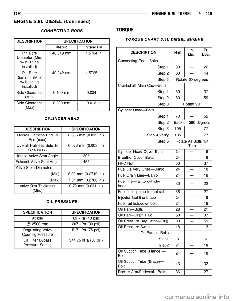
CONNECTING RODS
DESCRIPTION SPECIFICATION
Metric Standard
Pin Bore
Diameter (Min.
w/ bushing
installed)40.019 mm 1.5764 in.
Pin Bore
Diameter (Max.
w/ bushing
installed)40.042 mm 1.5765 in.
Side Clearance
(Min)0.100 mm 0.004 in.
Side Clearance
(Max)0.330 mm 0.013 in.
CYLINDER HEAD
DESCRIPTION SPECIFICATION
Overall Flatness End To
End (max)0.305 mm (0.012 in.)
Overall Flatness Side To
Side (Max)0.076 mm (0.003 in.)
Intake Valve Seat Angle 30É
Exhaust Valve Seat Angle 45É
Valve Stem Diameter
(Min) 6.96 mm (0.2740 in.)
(Max) 7.01 mm (0.2760 in.)
Valve Rim Thickness
(Min.)0.79 mm (0.031 in.)
OIL PRESSURE
SPECIFICATION SPECIFICATION
At Idle 69 kPa (10 psi)
@ 2500 rpm 207 kPa (30 psi)
Regulating Valve
Opening Pressure517 kPa (75 psi)
Oil Filter Bypass
Pressure Setting344.75 kPa (50 psi)
TORQUE
TORQUE CHART 5.9L DIESEL ENGINE
DESCRIPTION N´mIn.
Lbs.Ft.
Lbs.
Connecting RodÐBolts
Step 1 30 Ð 22
Step 2 60 Ð 44
Step 3 Rotate 60 degrees
Crankshaft Main CapÐBolts
Step 1 50 37
Step 2 80 59
Step 3 Rotate 90É
Cylinder HeadÐBolts
Step 1 70 Ð 52
Step 2 Back off 360 degrees
Step 3 105 Ð 77
Step 4 Verify 105 Ð 77
Step 5 Rotate All Bolts 1/4
Turn
Cylinder Head Cover Bolts 24 Ð 18
Breather Cover Bolts 24 Ð 18
HPC Nut 50 37
Fuel Delivery LinesÐBanjo 24 Ð 18
Fuel Drain LineÐBanjo 24 Ð 18
Fuel lineÐrail to cylinder
head30 Ð 22
Fuel lineÐpump to fuel rail 36 Ð 27
Injector fuel line brace 24 Ð 18
Fuel rail holddown bolt 24 18
Oil PanÐBolts 28 Ð 21
Oil PanÐDrain Plug 50 Ð 37
Oil Pressure RegulatorÐPlug 80 Ð 59
Oil Pressure Switch 18 Ð 13
Oil PumpÐBolts
Step1 8 Ð 6
Step2 24 Ð 18
Oil Suction Tube (Flange)Ð
Bolts24 Ð 18
Oil Suction Tube (Brace)Ð
Bolt43 Ð 32
Rocker Arm/PedestalÐBolts 36 Ð 27
DRENGINE 5.9L DIESEL 9 - 245
ENGINE 5.9L DIESEL (Continued)
Page 1473 of 2627
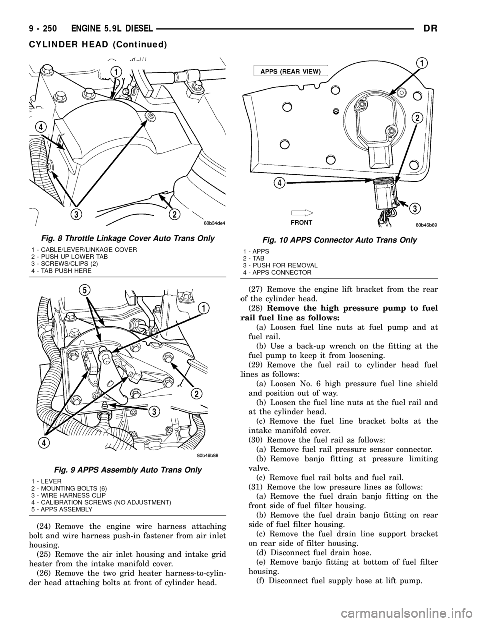
(24) Remove the engine wire harness attaching
bolt and wire harness push-in fastener from air inlet
housing.
(25) Remove the air inlet housing and intake grid
heater from the intake manifold cover.
(26) Remove the two grid heater harness-to-cylin-
der head attaching bolts at front of cylinder head.(27) Remove the engine lift bracket from the rear
of the cylinder head.
(28)Remove the high pressure pump to fuel
rail fuel line as follows:
(a) Loosen fuel line nuts at fuel pump and at
fuel rail.
(b) Use a back-up wrench on the fitting at the
fuel pump to keep it from loosening.
(29) Remove the fuel rail to cylinder head fuel
lines as follows:
(a) Loosen No. 6 high pressure fuel line shield
and position out of way.
(b) Loosen the fuel line nuts at the fuel rail and
at the cylinder head.
(c) Remove the fuel line bracket bolts at the
intake manifold cover.
(30) Remove the fuel rail as follows:
(a) Remove fuel rail pressure sensor connector.
(b) Remove banjo fitting at pressure limiting
valve.
(c) Remove fuel rail bolts and fuel rail.
(31) Remove the low pressure lines as follows:
(a) Remove the fuel drain banjo fitting on the
front side of fuel filter housing.
(b) Remove the fuel drain banjo fitting on rear
side of fuel filter housing.
(c) Remove the fuel drain line support bracket
on rear side of filter housing.
(d) Disconnect fuel drain hose.
(e) Remove banjo fitting at bottom of fuel filter
housing.
(f) Disconnect fuel supply hose at lift pump.
Fig. 8 Throttle Linkage Cover Auto Trans Only
1 - CABLE/LEVER/LINKAGE COVER
2 - PUSH UP LOWER TAB
3 - SCREWS/CLIPS (2)
4 - TAB PUSH HERE
Fig. 9 APPS Assembly Auto Trans Only
1 - LEVER
2 - MOUNTING BOLTS (6)
3 - WIRE HARNESS CLIP
4 - CALIBRATION SCREWS (NO ADJUSTMENT)
5 - APPS ASSEMBLY
Fig. 10 APPS Connector Auto Trans Only
1 - APPS
2-TAB
3 - PUSH FOR REMOVAL
4 - APPS CONNECTOR
9 - 250 ENGINE 5.9L DIESELDR
CYLINDER HEAD (Continued)
Page 1474 of 2627
(32) Disconnect fuel heater, water in fuel sensor,
and fuel lift pump connectors.
(33) Remove the fuel filter assembly-to-cylinder
head bolts and remove filter assembly from vehicle.
(34) Remove wire harness P-clip from cylinder
head (located behind filter housing).
(35) Remove the cylinder head cover(Refer to 9 -
ENGINE/CYLINDER HEAD/CYLINDER HEAD
COVER(S) - REMOVAL).
(36) Disconnect rocker housing injector harness
connectors.
(37) Remove injector harness nuts from injectors.
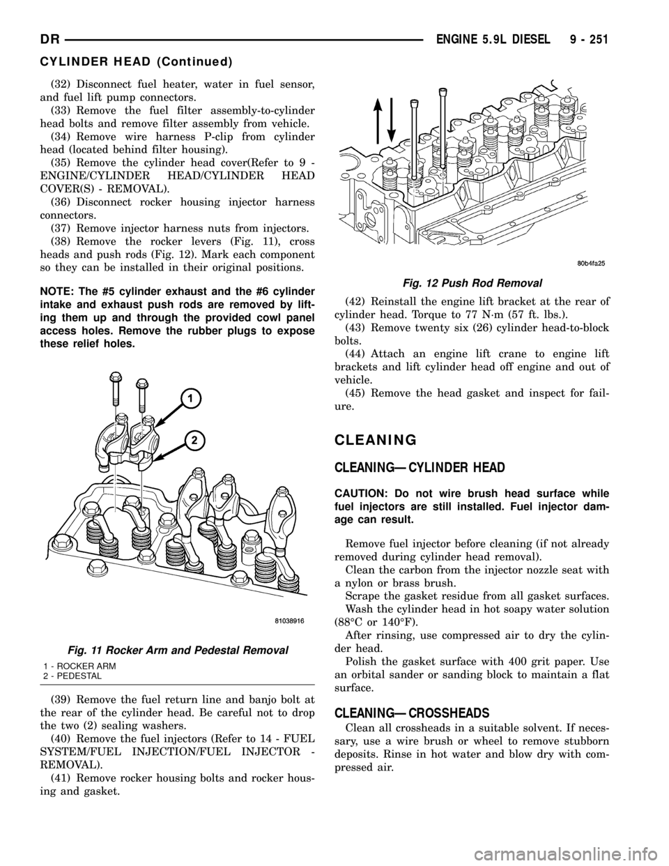
(38) Remove the rocker levers (Fig. 11), cross
heads and push rods (Fig. 12). Mark each component
so they can be installed in their original positions.
NOTE: The #5 cylinder exhaust and the #6 cylinder
intake and exhaust push rods are removed by lift-
ing them up and through the provided cowl panel
access holes. Remove the rubber plugs to expose
these relief holes.
(39) Remove the fuel return line and banjo bolt at
the rear of the cylinder head. Be careful not to drop
the two (2) sealing washers.
(40) Remove the fuel injectors (Refer to 14 - FUEL
SYSTEM/FUEL INJECTION/FUEL INJECTOR -
REMOVAL).
(41) Remove rocker housing bolts and rocker hous-
ing and gasket.(42) Reinstall the engine lift bracket at the rear of
cylinder head. Torque to 77 N´m (57 ft. lbs.).
(43) Remove twenty six (26) cylinder head-to-block
bolts.
(44) Attach an engine lift crane to engine lift
brackets and lift cylinder head off engine and out of
vehicle.
(45) Remove the head gasket and inspect for fail-
ure.
CLEANING
CLEANINGÐCYLINDER HEAD
CAUTION: Do not wire brush head surface while
fuel injectors are still installed. Fuel injector dam-
age can result.
Remove fuel injector before cleaning (if not already
removed during cylinder head removal).
Clean the carbon from the injector nozzle seat with
a nylon or brass brush.
Scrape the gasket residue from all gasket surfaces.
Wash the cylinder head in hot soapy water solution
(88ÉC or 140ÉF).
After rinsing, use compressed air to dry the cylin-
der head.
Polish the gasket surface with 400 grit paper. Use
an orbital sander or sanding block to maintain a flat
surface.
CLEANINGÐCROSSHEADS
Clean all crossheads in a suitable solvent. If neces-
sary, use a wire brush or wheel to remove stubborn
deposits. Rinse in hot water and blow dry with com-
pressed air.
Fig. 11 Rocker Arm and Pedestal Removal
1 - ROCKER ARM
2 - PEDESTAL
Fig. 12 Push Rod Removal
DRENGINE 5.9L DIESEL 9 - 251
CYLINDER HEAD (Continued)