DODGE RAM 1999 Service Repair Manual
Manufacturer: DODGE, Model Year: 1999, Model line: RAM, Model: DODGE RAM 1999Pages: 1691, PDF Size: 40.34 MB
Page 191 of 1691

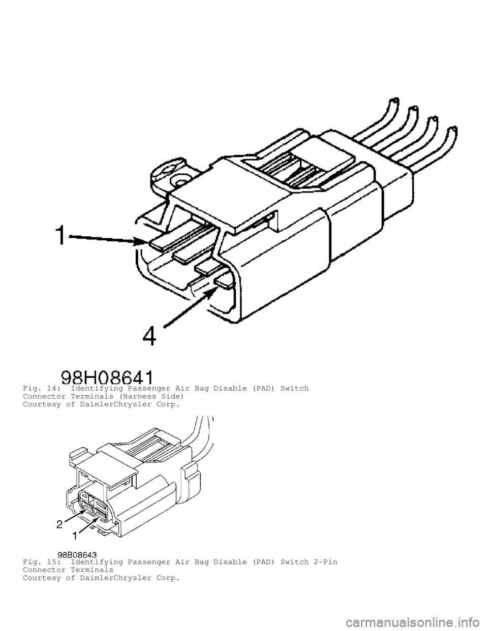
Fig. 14: Identifying Passenger Air Bag Disable (PAD) Switch
Connector Terminals (Harness Side)
Courtesy of DaimlerChrysler Corp.
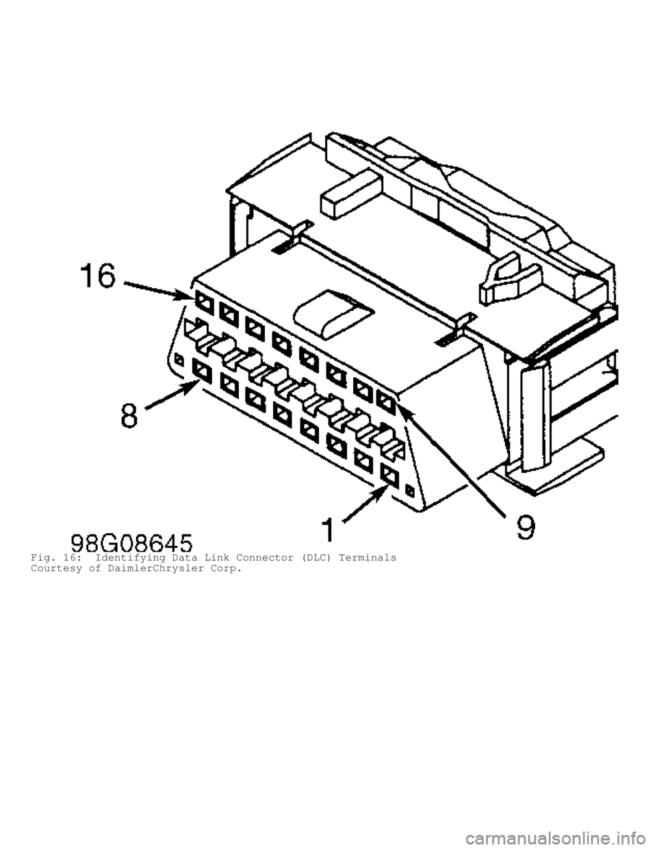
Fig. 15: Identifying Passenger Air Bag Disable (PAD) Switch 2-Pin
Connector Terminals
Courtesy of DaimlerChrysler Corp.
Page 192 of 1691

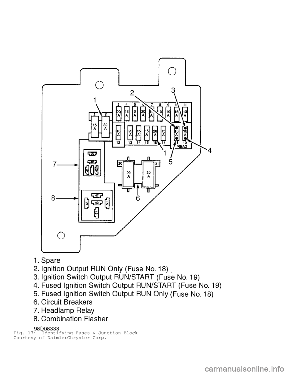
Fig. 16: Identifying Data Link Connector (DLC) Terminals
Courtesy of DaimlerChrysler Corp.
Page 193 of 1691

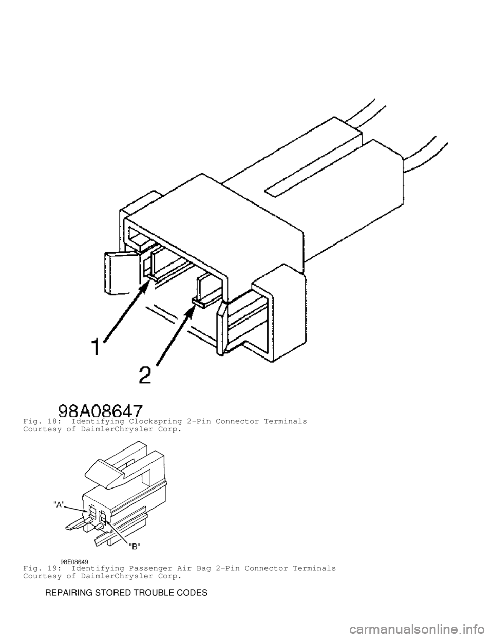
Fig. 17: Identifying Fuses & Junction Block
Courtesy of DaimlerChrysler Corp.
Page 194 of 1691

Fig. 18: Identifying Clockspring 2-Pin Connector Terminals
Courtesy of DaimlerChrysler Corp.
Fig. 19: Identifying Passenger Air Bag 2-Pin Connector Terminals
Courtesy of DaimlerChrysler Corp.
REPAIRING STORED TROUBLE CODES
Page 195 of 1691

NOTE: All active codes must be resolved before diagnosing store
codes.
1) Raise and support vehicle. Start engine and let idle with
transmission in PARK position. Wiggle wiring harness and connectors of
air bag system and rotate steering wheel from stop to stop.
2) Visually inspect related wire harness connectors. Look for
broken, bent, pushed out, spread, corroded or contaminated terminals.
Also, look for chafed, pierced, pinched or partially broken wires.
3) Check for trouble codes as you work through system. If
stored trouble code becomes active, perform appropriate diagnostic
test. If stored code is reproducible, repair or replace wiring
harness, harness connector or terminals or replace component as
necessary.
CLUSTER MESSAGE MISMATCH
NOTE: Perform AIR BAG VERIFICATION TEST after
all repairs. Each time a connector is disconnected, inspect
it to ensure it is in good condition. Always focus on circuit
being tested. Dirt, water and corrosion, are most common
problems in connectors. Due to manufacturer changes in wire
colors, use terminal identification whenever possible.
1) If AIR BAG warning light is on, go to next step. If AIR
BAG warning light is not on, go to step 5).
2) Using DRB, select PASSIVE RESTRAINTS, AIRBAG and MONITOR
DISPLAY. Read WARNING LAMP STATUS. If DRB does not display MIC LAMP
STATUS ON, replace instrument cluster. If DRB displays MIC LAMP STATUS
ON, go to next step.
3) If DRB displays ACM LAMP REQUEST: ON, go to next step. If
DRB does not display ACM LAMP REQUEST: ON, replace instrument cluster.
4) If there are no potential causes for this DTC remaining,
ACM is assumed to be defective. Replace ACM. See
AIR BAG CONTROL MODULE (ACM) under REMOVAL & INSTALLATION.
NOTE: If AIR BAG warning light is defective, instrument cluster
will flash seat belt light for 30 seconds starting 10 seconds
after bulb check stops.
5) Using DRB, read air bag control module active codes
(messages). If CLUSTER MISMATCH is only active message, go to next
step. If other messages are present, go to appropriate diagnostic test
to continue diagnosis.
6) If seat belt warning light flashes for 30 seconds after
bulb check is complete, replace instrument cluster. If seat belt
warning light does not flashes for 30 seconds after bulb check is
complete, go to next step.
7) Using DRB, select PASSIVE RESTRAINTS, AIRBAG and MONITOR
DISPLAY. Read WARNING LAMP STATUS. If DRB displays ACM LAMP REQUEST:
OFF, go to next step. If DRB does not display ACM LAMP REQUEST: OFF,
replace instrument cluster.
8) If DRB displays MIC LAMP REQUEST: OFF, go to next step. If
DRB does not display MIC LAMP REQUEST: OFF, replace instrument
cluster.
9) If there are no potential causes for this DTC remaining,
ACM is assumed to be defective. Replace ACM. See
AIR BAG CONTROL MODULE (ACM) under REMOVAL & INSTALLATION.
DRIVER SQUIB CIRCUIT OPEN
NOTE: Perform AIR BAG VERIFICATION TEST after
all repairs. Each time a connector is disconnected, inspect
Page 196 of 1691

it to ensure it is in good condition. Always focus on circuit
being tested. Dirt, water and corrosion, are most common
problems in connectors. Due to manufacturer changes in wire
colors, use terminal identification whenever possible.
1) Disconnect battery and wait 2 minutes before proceeding.
Disconnect driver-side air bag module squib connector. Connect a
jumper wire between driver-side air bag (squib) 2-pin connector
terminal No. 1 (Black/Light Blue wire) and terminal No. 2 (Dark
Green/Light Blue wire). Turn ignition on (engine off). Reconnect
battery. Using DRB, read active codes. If DRB displays DRIVER SQUIB
CIRCUIT SHORTED, replace driver-side air bag module. If not, go to
next step.
2) Disconnect clockspring 2-pin connector. Connect a jumper
wire between clockspring 2-pin connector terminals No. 1 (Black/Light
Blue wire) and No. 2 (Dark Green/Light Blue wire). Using DRB, read
active codes. If DRB displays DRIVER SQUIB CIRCUIT SHORTED, replace
clockspring. If not, go to next step.
3) Disconnect battery and wait 2 minutes before proceeding.
Remove jumper wires. Disconnect ACM connector. ACM is located under
instrument panel, on transmission tunnel. Using an ohmmeter, check
resistance between ACM connector terminal No. 6 (Dark Green/Light Blue
wire) and clockspring 2-pin connector terminal No. 2 (Dark Green/Light\
Blue wire). If resistance is less than 5 ohms, go to next step. If
resistance is more than 5 ohms, repair open or high resistance in Dark
Green/Light Blue wire.
4) Check resistance between ACM connector terminal No. 5
(Black/Light Blue wire) and clockspring 2-pin connector terminal No. 1\
(Black/Light Blue wire). If resistance is less than 5 ohms, go to next\
step. If resistance is more than 5 ohms, repair open or high
resistance in Black/Light Blue wire.
5) If there are no potential causes for this DTC remaining,
ACM is assumed to be defective. Replace ACM. See
AIR BAG CONTROL MODULE (ACM) under REMOVAL & INSTALLATION.
DRIVER SQUIB CIRCUIT SHORTED
NOTE: Perform AIR BAG VERIFICATION TEST after
all repairs. Each time a connector is disconnected, inspect
it to ensure it is in good condition. Always focus on circuit
being tested. Dirt, water and corrosion, are most common
problems in connectors. Due to manufacturer changes in wire
colors, use terminal identification whenever possible.
1) Disconnect battery and wait 2 minutes before proceeding.
Ensure driver-side air bag module connector is completely connected
before disconnecting it. If driver-side air bag module connector is
not completely connected, reconnect it. If driver-side air bag
connector is completely connected, go to next step.
2) Disconnect driver-side air bag module. Turn ignition on
(engine off). Reconnect battery. Using DRB, read active codes. If DRB
displays DRIVER SQUIB CIRCUIT OPEN, replace driver-side air bag
module. If not, go to next step.
3) Disconnect clockspring 2-pin connector. Using DRB, read
active codes. If DRB displays DRIVER SQUIB CIRCUIT OPEN, replace
clockspring. If not, go to next step.
4) Turn ignition off, disconnect battery and wait 2 minutes
before proceeding. Disconnect passenger-side air bag module connector.
Using an ohmmeter, check resistance between clockspring 2-pin
connector terminal No. 1 (Black/Light Blue wire) and passenger-side
air bag 2-pin connector terminal "A" (Black/Yellow wire). If
resistance is less than 5 ohms, repair short between Black/Light Blue
wire and Black/Yellow wire. If resistance is more than 5 ohms, go to
Page 197 of 1691

next step.
5) Using an ohmmeter, check resistance between clockspring 2-
pin connector terminals No. 1 (Black/Light Blue wire) and No. 2 (Dark\
Green/Light Blue wire). If resistance is less than 5 ohms, repair
short between Dark Green/Light Blue wire and Black/Light Blue wire. If
resistance is more than 5 ohms, go to next step.
6) If there are no potential causes for this DTC remaining,
ACM is assumed to be defective. Replace ACM. See
AIR BAG CONTROL MODULE (ACM) under REMOVAL & INSTALLATION.
DRIVER SQUIB CIRCUIT SHORTED TO BATTERY
NOTE: Perform AIR BAG VERIFICATION TEST after
all repairs. Each time a connector is disconnected, inspect
it to ensure it is in good condition. Always focus on circuit
being tested. Dirt, water and corrosion, are most common
problems in connectors. Due to manufacturer changes in wire
colors, use terminal identification whenever possible.
1) Disconnect battery and wait 2 minutes before proceeding.
Disconnect driver-side air bag module. Turn ignition on and reconnect
battery. Using DRB, read active codes. If DRB does not display DRIVER
SQUIB CIRCUIT SHORTED TO VOLTAGE, replace driver-side air bag module.
If DRB displays DRIVER SQUIB CIRCUIT SHORTED TO VOLTAGE, go to next
step.
2) Disconnect clockspring 2-pin connector. Using DRB, read
active codes. If DRB does not display DRIVER SQUIB CIRCUIT SHORTED TO
VOLTAGE, replace clockspring. If DRB displays DRIVER SQUIB CIRCUIT
SHORTED TO VOLTAGE, go to next step.
3) Disconnect battery and wait 2 minutes before proceeding.
Disconnect ACM 23-pin connector. Using a voltmeter, check voltage
between ground and clockspring connector terminals No. 1 (Black/Light
Blue wire) and No. 2 (Dark Green/Light Blue wire). If voltage is more\
than 5 volts on either circuit, repair short to voltage in Dark
Green/Light Blue wire or Black/Light Blue wire. If voltage is less
than 5 volts on either circuit, go to next step.
4) If there are no potential causes for this DTC remaining,
ACM is assumed to be defective. Replace ACM. See
AIR BAG CONTROL MODULE (ACM) under REMOVAL & INSTALLATION.
DRIVER SQUIB CIRCUIT SHORTED TO GROUND
NOTE: Perform AIR BAG VERIFICATION TEST after
all repairs. Each time a connector is disconnected, inspect
it to ensure it is in good condition. Always focus on circuit
being tested. Dirt, water and corrosion, are most common
problems in connectors. Due to manufacturer changes in wire
colors, use terminal identification whenever possible.
1) Disconnect battery and wait 2 minutes before proceeding.
Disconnect driver-side air bag module. Turn ignition on (engine off)
and reconnect battery. Using DRB, read active codes. If DRB does not
display DRIVER SQUIB CIRCUIT SHORTED TO GROUND, replace driver-side
air bag module. If DRB displays DRIVER SQUIB CIRCUIT SHORTED TO
GROUND, go to next step.
2) Disconnect clockspring 2-pin connector. Using DRB, read
active codes. If DRB does not display DRIVER SQUIB CIRCUIT SHORTED TO
GROUND, replace clockspring. If DRB displays DRIVER SQUIB CIRCUIT
SHORTED TO GROUND, go to next step.
3) Disconnect battery and wait 2 minutes before proceeding.
Disconnect ACM 23-pin connector. Using an ohmmeter, check resistance
between ground and clockspring connector terminals No. 1 (Black/Light
Blue wire) and No. 2 (Dark Green/Light Blue wire). If resistance is
Page 198 of 1691

more than 5 ohms on either circuit, repair short to ground in Dark
Green/Light Blue wire or Black/Light Blue wire. If resistance is less
than 5 ohms on either circuit, go to next step.
4) If there are no potential causes for this DTC remaining,
ACM is assumed to be defective. Replace ACM. See
AIR BAG CONTROL MODULE (ACM) under REMOVAL & INSTALLATION.
LOSS OF IGNITION RUN ONLY
NOTE: Perform AIR BAG VERIFICATION TEST after
all repairs. Each time a connector is disconnected, inspect
it to ensure it is in good condition. Always focus on circuit
being tested. Dirt, water and corrosion, are most common
problems in connectors. Due to manufacturer changes in wire
colors, use terminal identification whenever possible.
1) Remove and inspect fuse No. 18 located in junction block.
If fuse is blown, go to step 5). If fuse is good, go to next step.
2) Using a voltmeter, check voltage between ground and
ignition switch output RUN circuit at fuse No. 18. If voltage is less
than 10 volts, repair open ignition switch output RUN circuit. If
voltage is more than 10 volts, go to next step.
3) Reinstall fuse No. 18. Disconnect battery and wait 2
minutes before proceeding. Disconnect ACM connector. Turn ignition on,
then reconnect battery. Using a voltmeter, check voltage between
ground and ACM connector terminal No. 15 (Dark Blue/Yellow wire). If
voltage is more than 10 volts, go to next step. If voltage is less
than 10 volts, repair open in Dark Blue/Yellow wire.
4) If there are no potential causes for this DTC remaining,
ACM is assumed to be defective. Replace ACM. See
AIR BAG CONTROL MODULE (ACM) under REMOVAL & INSTALLATION.
5) Turn ignition off. Using an ohmmeter, check resistance
between ground and fused ignition switch output RUN circuit at fuse
No. 18. If resistance is more than 5 ohms, replace fuse No. 18 located
in junction block. If resistance is less than 5 ohms, go to next step.
6) Disconnect battery and wait 2 minutes before proceeding.
Disconnect ACM connector. Using an ohmmeter, check resistance between
ground and ACM connector terminal No. 15 (Dark Blue/Yellow wire). If
resistance is less than 5 ohms, repair fused ignition switch output
RUN circuit for a short to ground and replace fuse. If resistance is
more than 5 ohms, go to next step.
7) If there are no potential causes for this DTC remaining,
ACM is assumed to be defective. Replace ACM and fuse No. 18. See
AIR BAG CONTROL MODULE (ACM) under REMOVAL & INSTALLATION.
LOSS OF IGNITION RUN/START
NOTE: Perform AIR BAG VERIFICATION TEST after
all repairs. Each time a connector is disconnected, inspect
it to ensure it is in good condition. Always focus on circuit
being tested. Dirt, water and corrosion, are most common
problems in connectors. Due to manufacturer changes in wire
colors, use terminal identification whenever possible.
1) Remove and inspect fuse No. 19. If fuse is blown, go to
step 5). If fuse is good, go to next step.
2) Using a voltmeter, measure ignition switch output
RUN/START circuit between fuse No. 19 and ground. If voltage is less
than 10 volts, repair open ignition switch output RUN/START circuit.
If voltage is more than 10 volts, reinstall fuse No. 19. Disconnect
battery and wait 2 minutes before proceeding. Go to next step.
3) Disconnect ACM connector. Turn ignition on. Reconnect
battery. Using a voltmeter, check voltage between ground and ACM
Page 199 of 1691

connector terminal No. 14 (Light Green/Yellow wire). If voltage is
less than 10 volts, repair open in Light Green/Yellow wire. If voltage
is more than 10 volts, replace ACM.
4) If there are no potential causes for this DTC remaining,
ACM is assumed to be defective. Replace ACM. See
AIR BAG CONTROL MODULE (ACM) under REMOVAL & INSTALLATION.
5) Turn ignition off. Turn PAD switch to the ON position (if
equipped). Using an ohmmeter, check resistance at fused ignition
switch output RUN/START circuit between fuse No. 19 and ground. If
resistance is more than 5 ohms, replace fuse. If resistance is less
than 5 ohms, disconnect battery and wait 2 minutes before proceeding.
Disconnect ACM connector. Using an ohmmeter, check resistance between
ground and ACM connector terminal No. 14 (Light Green/Yellow wire). If\
resistance is less than 5 ohms, go to next step. If resistance is more
than 5 ohms, replace ACM and fuse No. 19.
6) Disconnect PAD switch. Using an ohmmeter, check resistance
between ground and ACM connector terminal No. 14 (Light Green/Yellow
wire). If resistance is less than 5 ohms, repair short to ground in
Light Green/Yellow wire and replace fuse No. 19. If resistance is more
than 5 ohms, replace fuse No. 19 located in junction block and go to
next step.
7) If there are no potential causes for this DTC remaining,
ACM is assumed to be defective. Replace ACM. See
AIR BAG CONTROL MODULE (ACM) under REMOVAL & INSTALLATION.
MISSING OR INVALID VIN MESSAGE
NOTE: Perform AIR BAG VERIFICATION TEST after
all repairs. Each time a connector is disconnected, inspect
it to ensure it is in good condition. Always focus on circuit
being tested. Dirt, water and corrosion, are most common
problems in connectors. Due to manufacturer changes in wire
colors, use terminal identification whenever possible.
1) Using DRB, select ENGINE PCM. If DRB displays NO RESPONSE
from PCM, go to NO RESPONSE FROM POWERTRAIN CONTROL MODULE under
VEHICLE COMMUNICATIONS. If DRB does not display NO RESPONSE from PCM
and vehicle is a Club Cab (BE) model, go to next step. If vehicle is
not a Club Cab (BE model), go step 3).
2) Using DRB, select PASSIVE RESTRAINTS, AIRBAG AND MONITORS.
Select VIN type (7th digit of VIN; VIN 2 or 3 on Club Cab). If DRB
does not display PCM VIN: BE, replace Powertrain Control Module (PCM).\
If DRB displays PCM VIN: BE, replace ACM.
3) Using DRB, select PASSIVE RESTRAINTS, AIRBAG AND MONITORS.
Select VIN type (7th digit of VIN; VIN 6 on Standard Cab). If DRB does\
not display PCM VIN: BR, replace Powertrain Control Module (PCM). If
DRB displays PCM VIN: BR, replace ACM.
NO CCD COMMUNICATION
NOTE: Perform AIR BAG VERIFICATION TEST after
all repairs. Each time a connector is disconnected, inspect
it to ensure it is in good condition. Always focus on circuit
being tested. Dirt, water and corrosion, are most common
problems in connectors. Due to manufacturer changes in wire
colors, use terminal identification whenever possible.
Using DRB, read active codes. If DRB displays NO CCD
COMMUNICATION as an active code, replace ACM. If DRB does not display
NO CCD COMMUNICATION as an active code, go to
REPAIRING STORED TROUBLE CODES .
NO CLUSTER CCD MESSAGE
Page 200 of 1691

NOTE: Perform AIR BAG VERIFICATION TEST after
all repairs. Each time a connector is disconnected, inspect
it to ensure it is in good condition. Always focus on circuit
being tested. Dirt, water and corrosion, are most common
problems in connectors. Due to manufacturer changes in wire
colors, use terminal identification whenever possible.
1) Using DRB, select ELECRO/MECH CLUSTER (MIC). If DRB
displays NO RESPONSE FROM MIC, go to
NO RESPONSE FROM INSTRUMENT CLUSTER under VEHICLE COMMUNICATIONS. If
DRB does not display NO RESPONSE FROM MIC, go to next step.
2) Using DRB, select PASSIVE RESTRAINTS, AIRBAG, MONITORS,
AND WARNING LAMP STATUS to read lamp messages from cluster. If ACM
lamp request displays NO RESP, replace ACM. If ACM lamp request does
not display NO RESP, go to next step.
3) Disconnect battery and wait 2 minutes before proceeding.
Disconnect ACM 23-pin connector. Disconnect mechanical instrument
cluster Black connector "A". Go to next step.
4) Using an ohmmeter, check resistance between mechanical
instrument cluster Black connector "A" terminal No. 9 (White/Black
wire) and ACM connector terminal No. 22 (White/Black wire). Also,
check resistance between mechanical instrument cluster Black connector
"A" terminal No. 10 (Violet/Brown wire) and ACM connector terminal No.\
21 (Violet/Brown wire). Go to next step.
5) If resistance is less than 5 ohms on both circuits,
replace instrument cluster. If resistance is more than 5 ohms on both
circuits, repair open in CCD bus circuit(s).
PASSENGER SQUIB CIRCUIT OPEN
NOTE: Perform AIR BAG VERIFICATION TEST after
all repairs. Each time a connector is disconnected, inspect
it to ensure it is in good condition. Always focus on circuit
being tested. Dirt, water and corrosion, are most common
problems in connectors. Due to manufacturer changes in wire
colors, use terminal identification whenever possible.
1) Disconnect battery and wait 2 minutes before proceeding.
Disconnect passenger-side air bag module. Connect a jumper wire
between passenger-side air bag module 2-pin connector terminals "A"
(Black/Yellow wire) and "B" (Dark Green/Yellow wire). Turn ignition
on. Reconnect battery. Using DRB, read active codes. If DRB displays
PASSENGER SIDE SQUIB SHORT, replace passenger-side air bag module. If
not, go to next step.
2) Remove jumper wire. Disconnect battery and wait 2 minutes
before proceeding. Disconnect ACM connector. Disconnect PAD switch 4-
pin connector. Using an ohmmeter, check resistance between passenger-
side air bag module 2-pin connector terminal "A" (Black/Yellow wire)
and PAD switch 4-pin connector (harness side) terminal No. 3
(Black/Yellow wire). If resistance is less than 5 ohms, go to next
step. If resistance is more than 5 ohms, repair open or high
resistance in Black/Yellow wire.
3) Using an ohmmeter, check resistance between PAD switch 4-
pin connector (harness side) terminal No. 3 (Black/Yellow wire) and
passenger-side air bag module 2-pin connector terminal "B" (Dark
Green/Yellow wire). If resistance is more than 5 ohms, repair open or
high resistance in Dark Green/Yellow wire. If resistance is less than
5 ohms, go to next step.
4) Using an ohmmeter, check resistance between PAD switch 4-
pin connector (harness side) terminals No. 2 (Violet/Yellow wire) an\
d
No. 4 (Dark Green/Yellow wire). Also, check resistance between PAD
switch 4-pin connector (harness side) terminals No. 1 (Brown/Yellow