wheel bolts DODGE RAM 2001 Service Repair Manual
[x] Cancel search | Manufacturer: DODGE, Model Year: 2001, Model line: RAM, Model: DODGE RAM 2001Pages: 2889, PDF Size: 68.07 MB
Page 2040 of 2889
(7) Install thrust bearing in overdrive unit sliding
hub. Use petroleum jelly to hold bearing in position.
CAUTION: Be sure the shoulder on the inside diam-
eter of the bearing is facing forward.
(8) Verify that splines in overdrive planetary gear
and overrunning clutch hub are aligned with Align-
ment Tool 6227-2. Overdrive unit cannot be installed
if splines are not aligned. If splines have rotated out
of alignment, unit will have to be disassembled to
realign splines.
(9) Carefully slide Alignment Tool 6227-2 out of
overdrive planetary gear and overrunning clutch
splines.
(10) Raise overdrive unit and carefully slide it
straight onto intermediate shaft. Insert park rod into
park lock reaction plug at same time. Avoid tilting
overdrive during installation as this could cause
planetary gear and overrunning clutch splines to
rotate out of alignment. If this occurs, it will be nec-
essary to remove and disassemble overdrive unit to
realign splines.
(11) Work overdrive unit forward on intermediate
shaft until seated against transmission case.
(12) Install bolts attaching overdrive unit to trans-
mission unit. Tighten bolts in diagonal pattern to 34
N´m (25 ft-lbs).
(13) Connect the transmission speed sensor and
overdrive wiring connectors.
(14) Install the transfer case, if equipped.
(15) Align and install rear propeller shaft, if nec-
essary. (Refer to 3 - DIFFERENTIAL & DRIVELINE/
PROPELLER SHAFT/PROPELLER SHAFT -
INSTALLATION)
OVERRUNNING CLUTCH
CAM/OVERDRIVE PISTON
RETAINER
DESCRIPTION
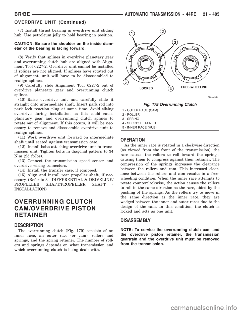
The overrunning clutch (Fig. 179) consists of an
inner race, an outer race (or cam), rollers and
springs, and the spring retainer. The number of roll-
ers and springs depends on what transmission and
which overrunning clutch is being dealt with.
OPERATION
As the inner race is rotated in a clockwise direction
(as viewed from the front of the transmission), the
race causes the rollers to roll toward the springs,
causing them to compress against their retainer. The
compression of the springs increases the clearance
between the rollers and cam. This increased clear-
ance between the rollers and cam results in a free-
wheeling condition. When the inner race attempts to
rotate counterclockwise, the action causes the rollers
to roll in the same direction as the race, aided by the
pushing of the springs. As the rollers try to move in
the same direction as the inner race, they are
wedged between the inner and outer races due to the
design of the cam. In this condition, the clutch is
locked and acts as one unit.
DISASSEMBLY
NOTE: To service the overrunning clutch cam and
the overdrive piston retainer, the transmission
geartrain and the overdrive unit must be removed
from the transmission.
Fig. 179 Overrunning Clutch
1 - OUTER RACE (CAM)
2 - ROLLER
3 - SPRING
4 - SPRING RETAINER
5 - INNER RACE (HUB)
BR/BEAUTOMATIC TRANSMISSION - 44RE 21 - 405
OVERDRIVE UNIT (Continued)
Page 2177 of 2889
reached. The PCM also considers vehicle loading,
grade and engine performance changes due to high
altitude in determining when to make WOT shifts. It
does this by measuring vehicle and engine accelera-
tion and then factoring in the shift time.
TRANSFER CASE LOW RANGE OPERATION
On four-wheel drive vehicles operating in low
range, the engine can accelerate to its peak more
rapidly than in Normal range, resulting in delayed
shifts and undesirable engine9flare.9The low range
governor pressure curve is also higher than normal
to initiate upshifts sooner. The PCM compares elec-
tronic vehicle speed signal used by the speedometer
to the transmission output shaft speed signal to
determine when the transfer case is in low range.
REMOVAL
(1) Hoist and support vehicle on safety stands.
(2) Remove transmission fluid pan and filter.
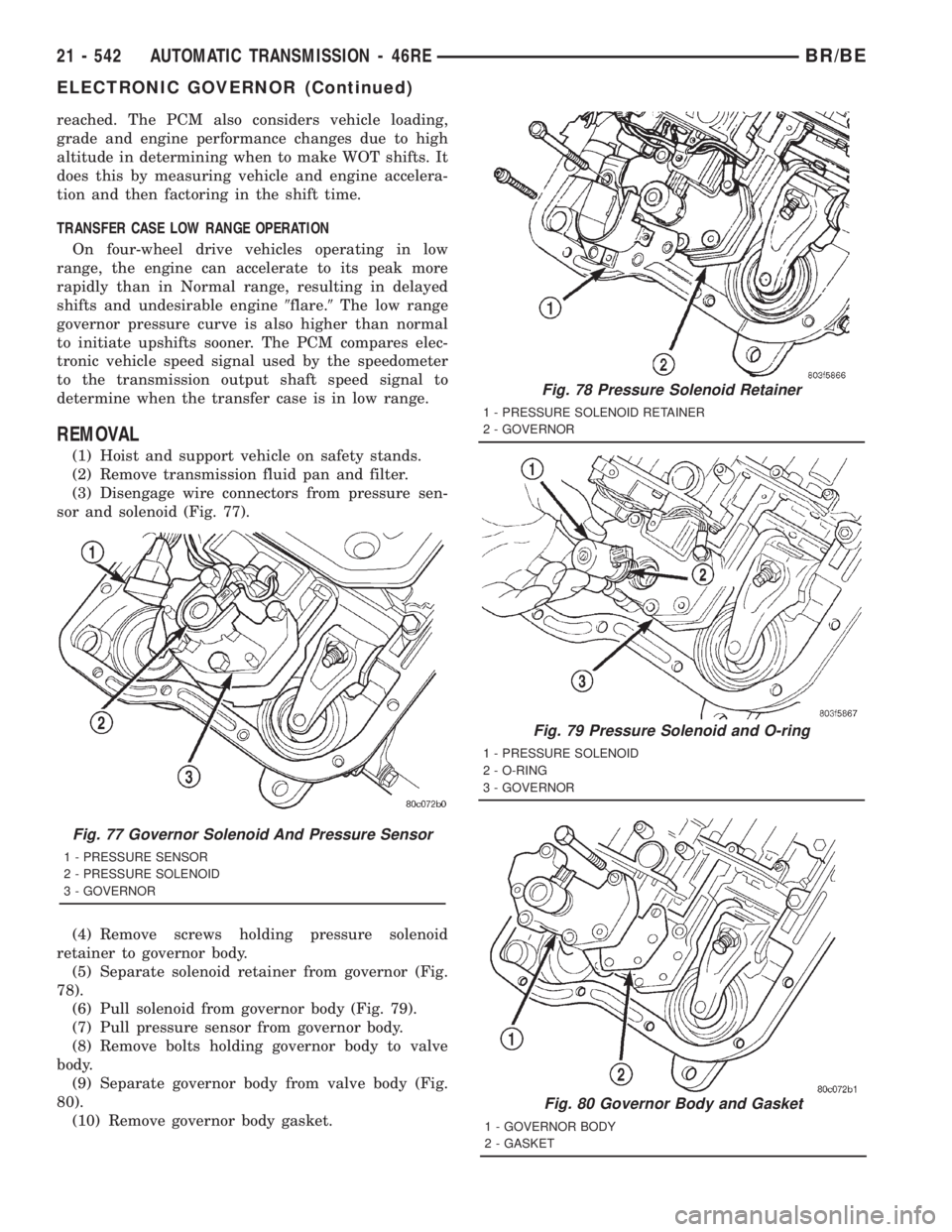
(3) Disengage wire connectors from pressure sen-
sor and solenoid (Fig. 77).
(4) Remove screws holding pressure solenoid
retainer to governor body.
(5) Separate solenoid retainer from governor (Fig.
78).
(6) Pull solenoid from governor body (Fig. 79).
(7) Pull pressure sensor from governor body.
(8) Remove bolts holding governor body to valve
body.
(9) Separate governor body from valve body (Fig.
80).
(10) Remove governor body gasket.
Fig. 78 Pressure Solenoid Retainer
1 - PRESSURE SOLENOID RETAINER
2 - GOVERNOR
Fig. 79 Pressure Solenoid and O-ring
1 - PRESSURE SOLENOID
2 - O-RING
3 - GOVERNOR
Fig. 80 Governor Body and Gasket
1 - GOVERNOR BODY
2 - GASKET
Fig. 77 Governor Solenoid And Pressure Sensor
1 - PRESSURE SENSOR
2 - PRESSURE SOLENOID
3 - GOVERNOR
21 - 542 AUTOMATIC TRANSMISSION - 46REBR/BE
ELECTRONIC GOVERNOR (Continued)
Page 2215 of 2889
(3) Push the overdrive off switch and wiring into
the shift lever.
(4) Install the overdrive off switch retainer onto
the shift lever.
OVERRUNNING CLUTCH
CAM/OVERDRIVE PISTON
RETAINER
DESCRIPTION
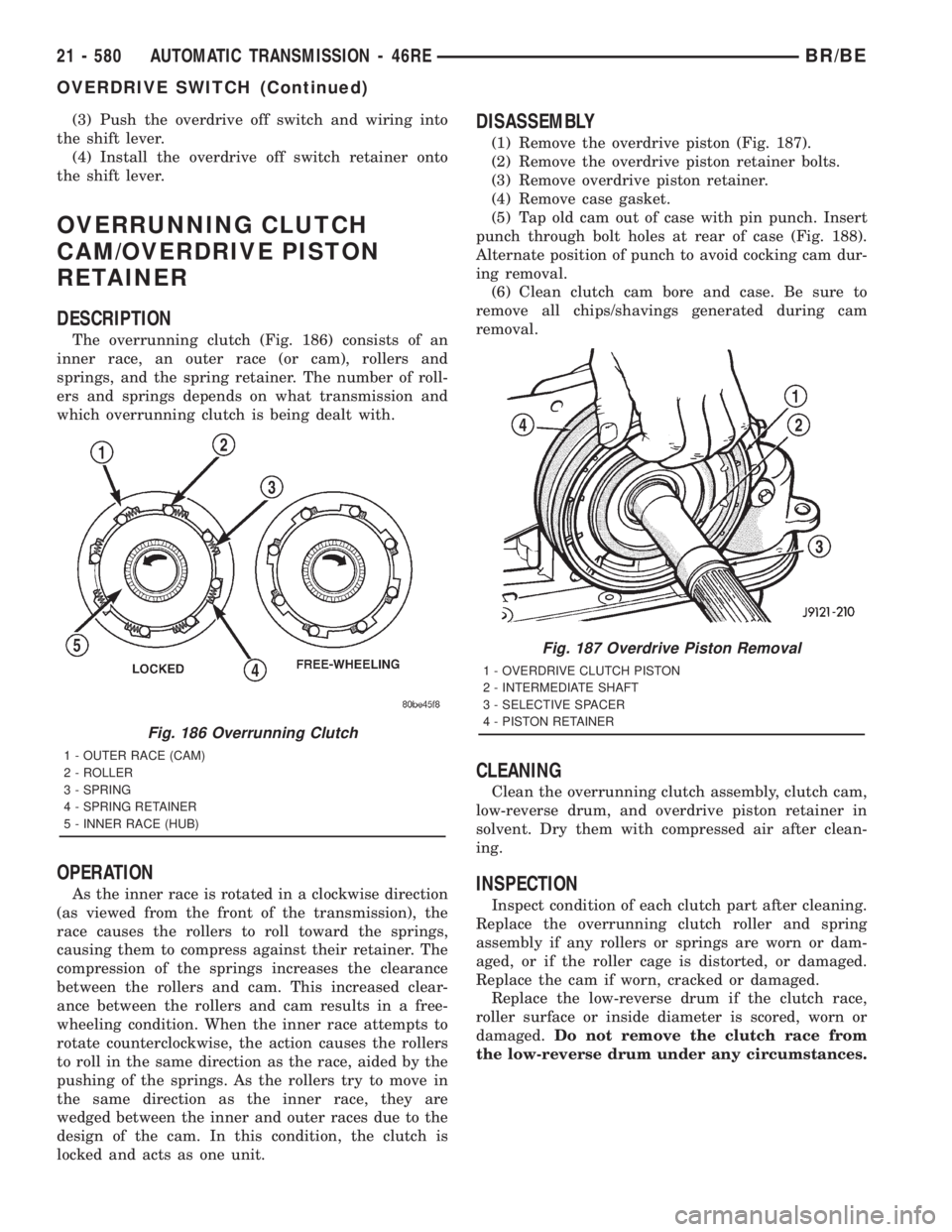
The overrunning clutch (Fig. 186) consists of an
inner race, an outer race (or cam), rollers and
springs, and the spring retainer. The number of roll-
ers and springs depends on what transmission and
which overrunning clutch is being dealt with.
OPERATION
As the inner race is rotated in a clockwise direction
(as viewed from the front of the transmission), the
race causes the rollers to roll toward the springs,
causing them to compress against their retainer. The
compression of the springs increases the clearance
between the rollers and cam. This increased clear-
ance between the rollers and cam results in a free-
wheeling condition. When the inner race attempts to
rotate counterclockwise, the action causes the rollers
to roll in the same direction as the race, aided by the
pushing of the springs. As the rollers try to move in
the same direction as the inner race, they are
wedged between the inner and outer races due to the
design of the cam. In this condition, the clutch is
locked and acts as one unit.
DISASSEMBLY
(1) Remove the overdrive piston (Fig. 187).
(2) Remove the overdrive piston retainer bolts.
(3) Remove overdrive piston retainer.
(4) Remove case gasket.
(5) Tap old cam out of case with pin punch. Insert
punch through bolt holes at rear of case (Fig. 188).
Alternate position of punch to avoid cocking cam dur-
ing removal.
(6) Clean clutch cam bore and case. Be sure to
remove all chips/shavings generated during cam
removal.
CLEANING
Clean the overrunning clutch assembly, clutch cam,
low-reverse drum, and overdrive piston retainer in
solvent. Dry them with compressed air after clean-
ing.
INSPECTION
Inspect condition of each clutch part after cleaning.
Replace the overrunning clutch roller and spring
assembly if any rollers or springs are worn or dam-
aged, or if the roller cage is distorted, or damaged.
Replace the cam if worn, cracked or damaged.
Replace the low-reverse drum if the clutch race,
roller surface or inside diameter is scored, worn or
damaged.Do not remove the clutch race from
the low-reverse drum under any circumstances.
Fig. 186 Overrunning Clutch
1 - OUTER RACE (CAM)
2 - ROLLER
3 - SPRING
4 - SPRING RETAINER
5 - INNER RACE (HUB)
Fig. 187 Overdrive Piston Removal
1 - OVERDRIVE CLUTCH PISTON
2 - INTERMEDIATE SHAFT
3 - SELECTIVE SPACER
4 - PISTON RETAINER
21 - 580 AUTOMATIC TRANSMISSION - 46REBR/BE
OVERDRIVE SWITCH (Continued)
Page 2347 of 2889
WIDE OPEN THROTTLE OPERATION
In wide-open throttle (WOT) mode, adaptive memory
in the PCM assures that up-shifts occur at the prepro-
grammed optimum speed. WOT operation is determined
from the throttle position sensor, which is also a part of
the emission control system. The initial setting for the
WOT upshift is below the optimum engine speed. As
WOT shifts are repeated, the PCM learns the time
required to complete the shifts by comparing the engine
speed when the shifts occur to the optimum speed. After
each shift, the PCM adjusts the shift point until the
optimum speed is reached. The PCM also considers
vehicle loading, grade and engine performance changes
due to high altitude in determining when to make WOT
shifts. It does this by measuring vehicle and engine
acceleration and then factoring in the shift time.
TRANSFER CASE LOW RANGE OPERATION
On four-wheel drive vehicles operating in low
range, the engine can accelerate to its peak more
rapidly than in Normal range, resulting in delayed
shifts and undesirable engine9flare.9The low range
governor pressure curve is also higher than normal
to initiate upshifts sooner. The PCM compares elec-
tronic vehicle speed signal used by the speedometer
to the transmission output shaft speed signal to
determine when the transfer case is in low range.
REMOVAL
(1) Hoist and support vehicle on safety stands.
(2) Remove transmission fluid pan and filter.
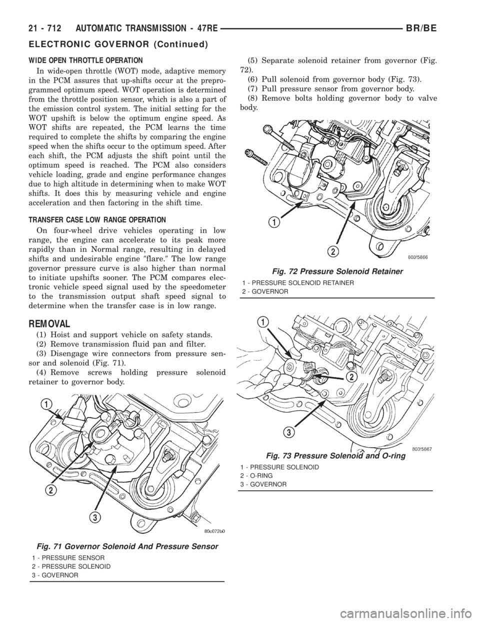
(3) Disengage wire connectors from pressure sen-
sor and solenoid (Fig. 71).
(4) Remove screws holding pressure solenoid
retainer to governor body.(5) Separate solenoid retainer from governor (Fig.
72).
(6) Pull solenoid from governor body (Fig. 73).
(7) Pull pressure sensor from governor body.
(8) Remove bolts holding governor body to valve
body.
Fig. 71 Governor Solenoid And Pressure Sensor
1 - PRESSURE SENSOR
2 - PRESSURE SOLENOID
3 - GOVERNOR
Fig. 72 Pressure Solenoid Retainer
1 - PRESSURE SOLENOID RETAINER
2 - GOVERNOR
Fig. 73 Pressure Solenoid and O-ring
1 - PRESSURE SOLENOID
2 - O-RING
3 - GOVERNOR
21 - 712 AUTOMATIC TRANSMISSION - 47REBR/BE
ELECTRONIC GOVERNOR (Continued)
Page 2386 of 2889
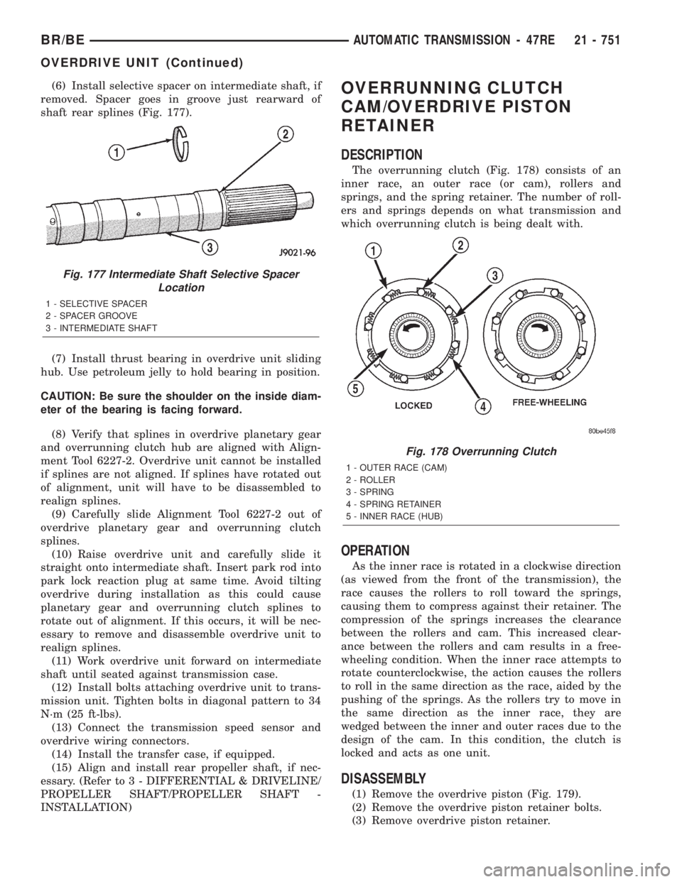
(6) Install selective spacer on intermediate shaft, if
removed. Spacer goes in groove just rearward of
shaft rear splines (Fig. 177).
(7) Install thrust bearing in overdrive unit sliding
hub. Use petroleum jelly to hold bearing in position.
CAUTION: Be sure the shoulder on the inside diam-
eter of the bearing is facing forward.
(8) Verify that splines in overdrive planetary gear
and overrunning clutch hub are aligned with Align-
ment Tool 6227-2. Overdrive unit cannot be installed
if splines are not aligned. If splines have rotated out
of alignment, unit will have to be disassembled to
realign splines.
(9) Carefully slide Alignment Tool 6227-2 out of
overdrive planetary gear and overrunning clutch
splines.
(10) Raise overdrive unit and carefully slide it
straight onto intermediate shaft. Insert park rod into
park lock reaction plug at same time. Avoid tilting
overdrive during installation as this could cause
planetary gear and overrunning clutch splines to
rotate out of alignment. If this occurs, it will be nec-
essary to remove and disassemble overdrive unit to
realign splines.
(11) Work overdrive unit forward on intermediate
shaft until seated against transmission case.
(12) Install bolts attaching overdrive unit to trans-
mission unit. Tighten bolts in diagonal pattern to 34
N´m (25 ft-lbs).
(13) Connect the transmission speed sensor and
overdrive wiring connectors.
(14) Install the transfer case, if equipped.
(15) Align and install rear propeller shaft, if nec-
essary. (Refer to 3 - DIFFERENTIAL & DRIVELINE/
PROPELLER SHAFT/PROPELLER SHAFT -
INSTALLATION)OVERRUNNING CLUTCH
CAM/OVERDRIVE PISTON
RETAINER
DESCRIPTION
The overrunning clutch (Fig. 178) consists of an
inner race, an outer race (or cam), rollers and
springs, and the spring retainer. The number of roll-
ers and springs depends on what transmission and
which overrunning clutch is being dealt with.
OPERATION
As the inner race is rotated in a clockwise direction
(as viewed from the front of the transmission), the
race causes the rollers to roll toward the springs,
causing them to compress against their retainer. The
compression of the springs increases the clearance
between the rollers and cam. This increased clear-
ance between the rollers and cam results in a free-
wheeling condition. When the inner race attempts to
rotate counterclockwise, the action causes the rollers
to roll in the same direction as the race, aided by the
pushing of the springs. As the rollers try to move in
the same direction as the inner race, they are
wedged between the inner and outer races due to the
design of the cam. In this condition, the clutch is
locked and acts as one unit.
DISASSEMBLY
(1) Remove the overdrive piston (Fig. 179).
(2) Remove the overdrive piston retainer bolts.
(3) Remove overdrive piston retainer.
Fig. 177 Intermediate Shaft Selective Spacer
Location
1 - SELECTIVE SPACER
2 - SPACER GROOVE
3 - INTERMEDIATE SHAFT
Fig. 178 Overrunning Clutch
1 - OUTER RACE (CAM)
2 - ROLLER
3 - SPRING
4 - SPRING RETAINER
5 - INNER RACE (HUB)
BR/BEAUTOMATIC TRANSMISSION - 47RE 21 - 751
OVERDRIVE UNIT (Continued)
Page 2665 of 2889
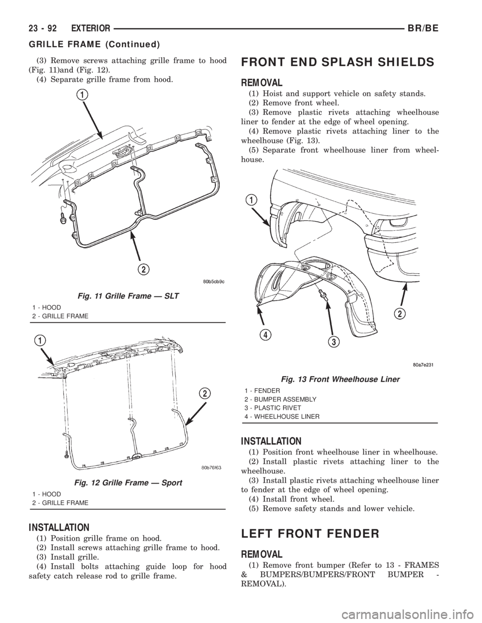
(3) Remove screws attaching grille frame to hood
(Fig. 11)and (Fig. 12).
(4) Separate grille frame from hood.
INSTALLATION
(1) Position grille frame on hood.
(2) Install screws attaching grille frame to hood.
(3) Install grille.
(4) Install bolts attaching guide loop for hood
safety catch release rod to grille frame.
FRONT END SPLASH SHIELDS
REMOVAL
(1) Hoist and support vehicle on safety stands.
(2) Remove front wheel.
(3) Remove plastic rivets attaching wheelhouse
liner to fender at the edge of wheel opening.
(4) Remove plastic rivets attaching liner to the
wheelhouse (Fig. 13).
(5) Separate front wheelhouse liner from wheel-
house.
INSTALLATION
(1) Position front wheelhouse liner in wheelhouse.
(2) Install plastic rivets attaching liner to the
wheelhouse.
(3) Install plastic rivets attaching wheelhouse liner
to fender at the edge of wheel opening.
(4) Install front wheel.
(5) Remove safety stands and lower vehicle.
LEFT FRONT FENDER
REMOVAL
(1) Remove front bumper (Refer to 13 - FRAMES
& BUMPERS/BUMPERS/FRONT BUMPER -
REMOVAL).
Fig. 11 Grille Frame Ð SLT
1 - HOOD
2 - GRILLE FRAME
Fig. 12 Grille Frame Ð Sport
1 - HOOD
2 - GRILLE FRAME
Fig. 13 Front Wheelhouse Liner
1 - FENDER
2 - BUMPER ASSEMBLY
3 - PLASTIC RIVET
4 - WHEELHOUSE LINER
23 - 92 EXTERIORBR/BE
GRILLE FRAME (Continued)
Page 2666 of 2889
(2) Remove air cleaner from wheelhouse (DIESEL
ONLY).
(3) Remove coolant overflow bottle (V-10 ONLY).
(4) Remove battery tray (Refer to 8 - ELECTRI-
CAL/BATTERY SYSTEM/TRAY - REMOVAL).
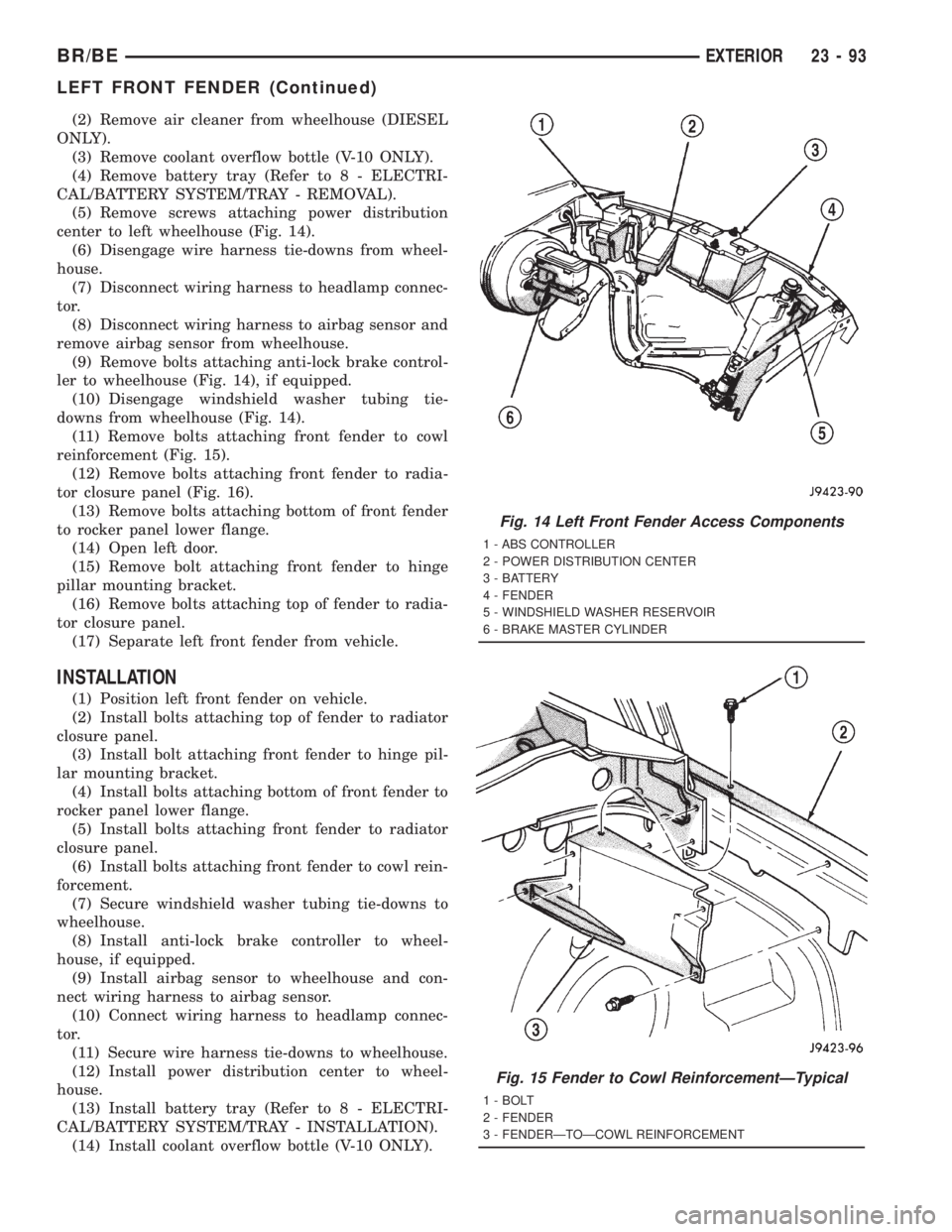
(5) Remove screws attaching power distribution
center to left wheelhouse (Fig. 14).
(6) Disengage wire harness tie-downs from wheel-
house.
(7) Disconnect wiring harness to headlamp connec-
tor.
(8) Disconnect wiring harness to airbag sensor and
remove airbag sensor from wheelhouse.
(9) Remove bolts attaching anti-lock brake control-
ler to wheelhouse (Fig. 14), if equipped.
(10) Disengage windshield washer tubing tie-
downs from wheelhouse (Fig. 14).
(11) Remove bolts attaching front fender to cowl
reinforcement (Fig. 15).
(12) Remove bolts attaching front fender to radia-
tor closure panel (Fig. 16).
(13) Remove bolts attaching bottom of front fender
to rocker panel lower flange.
(14) Open left door.
(15) Remove bolt attaching front fender to hinge
pillar mounting bracket.
(16) Remove bolts attaching top of fender to radia-
tor closure panel.
(17) Separate left front fender from vehicle.
INSTALLATION
(1) Position left front fender on vehicle.
(2) Install bolts attaching top of fender to radiator
closure panel.
(3) Install bolt attaching front fender to hinge pil-
lar mounting bracket.
(4) Install bolts attaching bottom of front fender to
rocker panel lower flange.
(5) Install bolts attaching front fender to radiator
closure panel.
(6) Install bolts attaching front fender to cowl rein-
forcement.
(7) Secure windshield washer tubing tie-downs to
wheelhouse.
(8) Install anti-lock brake controller to wheel-
house, if equipped.
(9) Install airbag sensor to wheelhouse and con-
nect wiring harness to airbag sensor.
(10) Connect wiring harness to headlamp connec-
tor.
(11) Secure wire harness tie-downs to wheelhouse.
(12) Install power distribution center to wheel-
house.
(13) Install battery tray (Refer to 8 - ELECTRI-
CAL/BATTERY SYSTEM/TRAY - INSTALLATION).
(14) Install coolant overflow bottle (V-10 ONLY).
Fig. 14 Left Front Fender Access Components
1 - ABS CONTROLLER
2 - POWER DISTRIBUTION CENTER
3 - BATTERY
4 - FENDER
5 - WINDSHIELD WASHER RESERVOIR
6 - BRAKE MASTER CYLINDER
Fig. 15 Fender to Cowl ReinforcementÐTypical
1 - BOLT
2 - FENDER
3 - FENDERÐTOÐCOWL REINFORCEMENT
BR/BEEXTERIOR 23 - 93
LEFT FRONT FENDER (Continued)
Page 2667 of 2889
(15) Install air cleaner (DIESEL ONLY).
(16) Install front bumper (Refer to 13 - FRAMES
& BUMPERS/BUMPERS/FRONT BUMPER -
INSTALLATION).
RIGHT FRONT FENDER
REMOVAL
(1) Remove front bumper (Refer to 13 - FRAMES
& BUMPERS/BUMPERS/FRONT BUMPER -
REMOVAL).
(2) Disconnect and isolate battery negative cable.
(3) Remove auxiliary battery and tray on right
side, if equipped.
(4) Disengage wire harness tie-downs from wheel-
house.
(5) Disconnect wiring harness to headlamp connec-
tor.
(6) Disconnect wiring harness to airbag sensor and
remove airbag sensor from wheelhouse.
(7) Remove front wheelhouse liner (Fig. 13) (Refer
to 23 - BODY/EXTERIOR/FRONT END SPLASH
SHIELDS - REMOVAL).
(8) Disengage air conditioning tubing from inner
fender clips.
(9) Remove bolts attaching front fender to cowl
reinforcement (Fig. 15).
(10) Remove bolts attaching front fender to radia-
tor closure panel.
(11) Remove bolts attaching bottom of front fender
to rocker panel lower flange (Fig. 17).
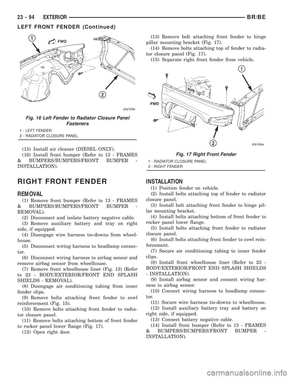
(12) Open right door.(13) Remove bolt attaching front fender to hinge
pillar mounting bracket (Fig. 17).
(14) Remove bolts attaching top of fender to radia-
tor closure panel (Fig. 17).
(15) Separate right front fender from vehicle.
INSTALLATION
(1) Position fender on vehicle.
(2) Install bolts attaching top of fender to radiator
closure panel.
(3) Install bolt attaching front fender to hinge pil-
lar mounting bracket.
(4) Install bolts attaching bottom of front fender to
rocker panel lower flange.
(5) Install bolts attaching front fender to radiator
closure panel.
(6) Install bolts attaching front fender to cowl rein-
forcement.
(7) Secure air conditioning tubing to inner fender
clips.
(8) Install front wheelhouse liner (Refer to 23 -
BODY/EXTERIOR/FRONT END SPLASH SHIELDS
- INSTALLATION).
(9) Install airbag sensor and connect wiring har-
ness to airbag sensor.
(10) Connect wiring harness to headlamp connec-
tor.
(11) Secure wire harness tie-downs to wheelhouse.
(12) Install auxiliary battery tray and battery on
right side, if equipped.
(13) Connect battery negative cable.
(14) Install front bumper (Refer to 13 - FRAMES
& BUMPERS/BUMPERS/FRONT BUMPER -
INSTALLATION).
Fig. 16 Left Fender to Radiator Closure Panel
Fasteners
1 - LEFT FENDER
2 - RADIATOR CLOSURE PANEL
Fig. 17 Right Front Fender
1 - RADIATOR CLOSURE PANEL
2 - RIGHT FENDER
23 - 94 EXTERIORBR/BE
LEFT FRONT FENDER (Continued)
Page 2668 of 2889
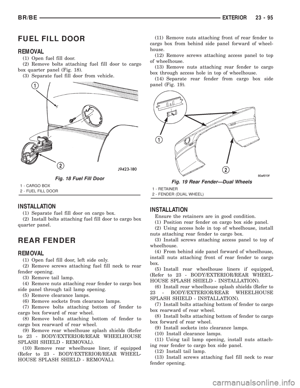
FUEL FILL DOOR
REMOVAL
(1) Open fuel fill door.
(2) Remove bolts attaching fuel fill door to cargo
box quarter panel (Fig. 18).
(3) Separate fuel fill door from vehicle.
INSTALLATION
(1) Separate fuel fill door on cargo box.
(2) Install bolts attaching fuel fill door to cargo box
quarter panel.
REAR FENDER
REMOVAL
(1) Open fuel fill door, left side only.
(2) Remove screws attaching fuel fill neck to rear
fender opening.
(3) Remove tail lamp.
(4) Remove nuts attaching rear fender to cargo box
side panel through tail lamp opening.
(5) Remove clearance lamps.
(6) Remove sockets from clearance lamps.
(7) Remove bolts attaching bottom of fender to
cargo box forward of rear wheel.
(8) Remove bolts attaching bottom of fender to
cargo box rearward of rear wheel.
(9) Remove rear wheelhouse splash shields (Refer
to 23 - BODY/EXTERIOR/REAR WHEELHOUSE
SPLASH SHIELD - REMOVAL).
(10) Remove rear wheelhouse liner, if equipped
(Refer to 23 - BODY/EXTERIOR/REAR WHEEL-
HOUSE SPLASH SHIELD - REMOVAL).(11) Remove nuts attaching front of rear fender to
cargo box from behind side panel forward of wheel-
house.
(12) Remove screws attaching access panel to top
of wheelhouse.
(13) Remove nuts attaching rear fender to cargo
box through access hole in top of wheelhouse.
(14) Separate rear fender from cargo box side
panel (Fig. 19).
INSTALLATION
Ensure the retainers are in good condition.
(1) Position rear fender on cargo box side panel.
(2) Using access hole in top of wheelhouse, install
nuts attaching rear fender to cargo box.
(3) Install screws attaching access panel to top of
wheelhouse.
(4) From behind side panel forward of wheelhouse,
install nuts attaching front of rear fender to cargo
box.
(5) Install rear wheelhouse liners if equipped,
(Refer to 23 - BODY/EXTERIOR/REAR WHEEL-
HOUSE SPLASH SHIELD - INSTALLATION).
(6) Install rear wheelhouse splash shields (Refer to
23 - BODY/EXTERIOR/REAR WHEELHOUSE
SPLASH SHIELD - INSTALLATION).
(7) Install bolts attaching bottom of fender to cargo
box rearward of rear wheel.
(8) Install bolts attaching bottom of fender to cargo
box forward of rear wheel.
(9) Install sockets into clearance lamps.
(10) Install clearance lamps.
(11) Using tail lamp opening, install nuts attach-
ing rear fender to cargo box side panel.
(12) Install tail lamp.
(13) Install screws attaching fuel fill neck to rear
fender opening.
Fig. 18 Fuel Fill Door
1 - CARGO BOX
2 - FUEL FILL DOORFig. 19 Rear FenderÐDual Wheels
1 - RETAINER
2 - FENDER (DUAL WHEEL)
BR/BEEXTERIOR 23 - 95
Page 2669 of 2889
REAR SPLASH SHIELD
REMOVAL
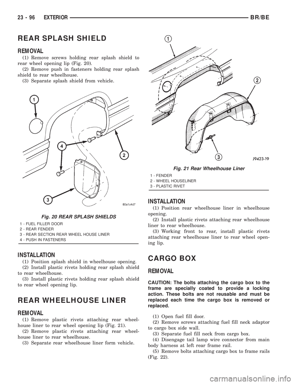
(1) Remove screws holding rear splash shield to
rear wheel opening lip (Fig. 20).
(2) Remove push in fasteners holding rear splash
shield to rear wheelhouse.
(3) Separate splash shield from vehicle.
INSTALLATION
(1) Position splash shield in wheelhouse opening.
(2) Install plastic rivets holding rear splash shield
to rear wheelhouse.
(3) Install plastic rivets holding rear splash shield
to rear wheel opening lip.
REAR WHEELHOUSE LINER
REMOVAL
(1) Remove plastic rivets attaching rear wheel-
house liner to rear wheel opening lip (Fig. 21).
(2) Remove plastic rivets attaching rear wheel-
house liner to rear wheelhouse.
(3) Separate rear wheelhouse liner form vehicle.
INSTALLATION
(1) Position rear wheelhouse liner in wheelhouse
opening.
(2) Install plastic rivets attaching rear wheelhouse
liner to rear wheelhouse.
(3) Working front to rear, install plastic rivets
attaching rear wheelhouse liner to rear wheel open-
ing lip.
CARGO BOX
REMOVAL
CAUTION: The bolts attaching the cargo box to the
frame are specially coated to provide a locking
action. These bolts are not reusable and must be
replaced each time the cargo box is removed or
replaced.
(1) Open fuel fill door.
(2) Remove screws attaching fuel fill neck adaptor
to cargo box side wall.
(3) Separate fuel fill neck from cargo box.
(4) Disengage tail lamp wire connector from main
body harness at left rear frame rail.
(5) Remove bolts attaching cargo box to frame rails
(Fig. 22).
Fig. 20 REAR SPLASH SHIELDS
1 - FUEL FILLER DOOR
2 - REAR FENDER
3 - REAR SECTION REAR WHEEL HOUSE LINER
4 - PUSH IN FASTENERS
Fig. 21 Rear Wheelhouse Liner
1 - FENDER
2 - WHEEL HOUSELINER
3 - PLASTIC RIVET
23 - 96 EXTERIORBR/BE