wheel size DODGE RAM 2001 Service Repair Manual
[x] Cancel search | Manufacturer: DODGE, Model Year: 2001, Model line: RAM, Model: DODGE RAM 2001Pages: 2889, PDF Size: 68.07 MB
Page 13 of 2889
VEHICLE SAFETY
CERTIFICATION LABEL
DESCRIPTION
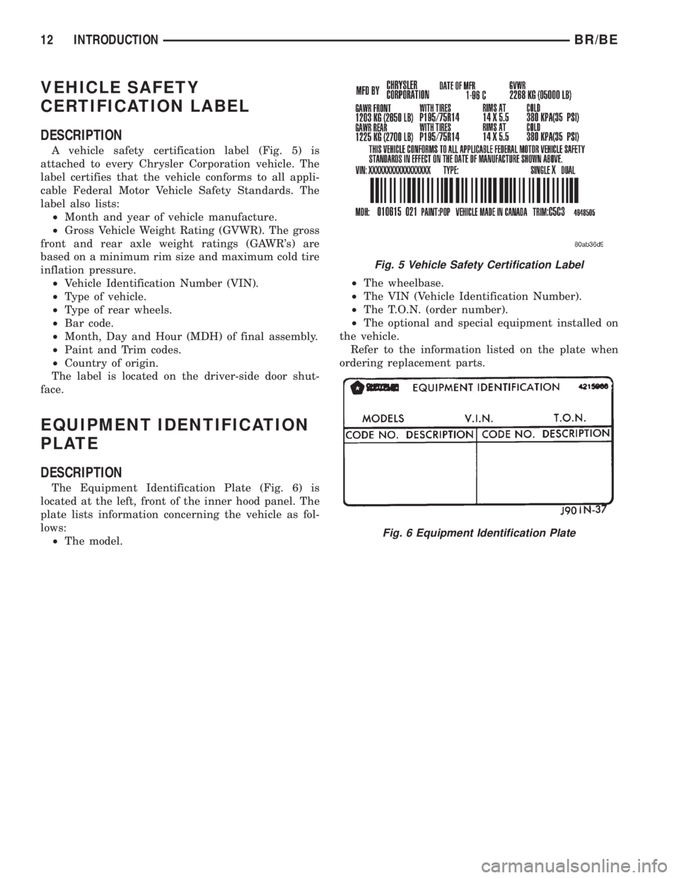
A vehicle safety certification label (Fig. 5) is
attached to every Chrysler Corporation vehicle. The
label certifies that the vehicle conforms to all appli-
cable Federal Motor Vehicle Safety Standards. The
label also lists:
²Month and year of vehicle manufacture.
²Gross Vehicle Weight Rating (GVWR). The gross
front and rear axle weight ratings (GAWR's) are
based on a minimum rim size and maximum cold tire
inflation pressure.
²Vehicle Identification Number (VIN).
²Type of vehicle.
²Type of rear wheels.
²Bar code.
²Month, Day and Hour (MDH) of final assembly.
²Paint and Trim codes.
²Country of origin.
The label is located on the driver-side door shut-
face.
EQUIPMENT IDENTIFICATION
PLATE
DESCRIPTION
The Equipment Identification Plate (Fig. 6) is
located at the left, front of the inner hood panel. The
plate lists information concerning the vehicle as fol-
lows:
²The model.²The wheelbase.
²The VIN (Vehicle Identification Number).
²The T.O.N. (order number).
²The optional and special equipment installed on
the vehicle.
Refer to the information listed on the plate when
ordering replacement parts.
Fig. 5 Vehicle Safety Certification Label
Fig. 6 Equipment Identification Plate
12 INTRODUCTIONBR/BE
Page 45 of 2889
OPERATION
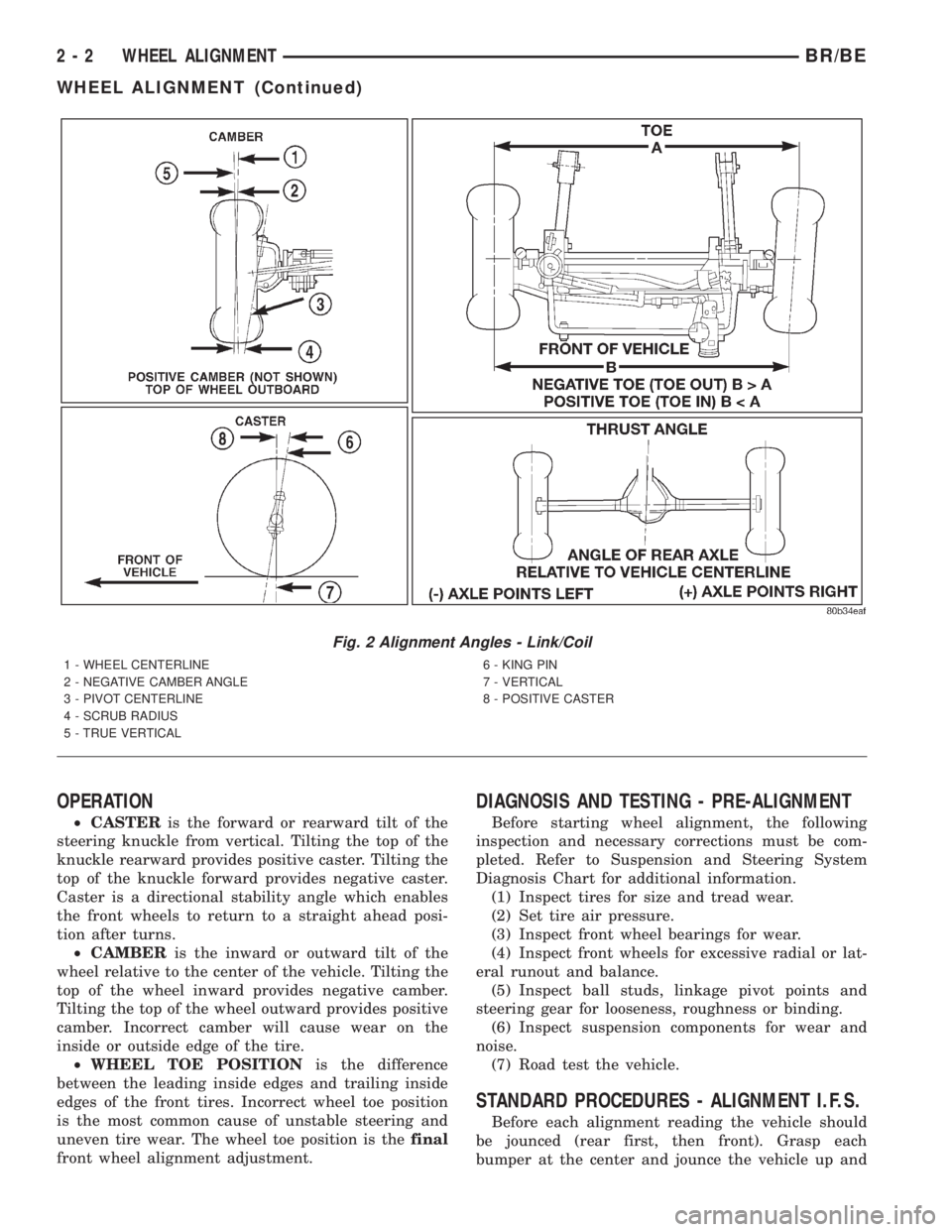
²CASTERis the forward or rearward tilt of the
steering knuckle from vertical. Tilting the top of the
knuckle rearward provides positive caster. Tilting the
top of the knuckle forward provides negative caster.
Caster is a directional stability angle which enables
the front wheels to return to a straight ahead posi-
tion after turns.
²CAMBERis the inward or outward tilt of the
wheel relative to the center of the vehicle. Tilting the
top of the wheel inward provides negative camber.
Tilting the top of the wheel outward provides positive
camber. Incorrect camber will cause wear on the
inside or outside edge of the tire.
²WHEEL TOE POSITIONis the difference
between the leading inside edges and trailing inside
edges of the front tires. Incorrect wheel toe position
is the most common cause of unstable steering and
uneven tire wear. The wheel toe position is thefinal
front wheel alignment adjustment.
DIAGNOSIS AND TESTING - PRE-ALIGNMENT
Before starting wheel alignment, the following
inspection and necessary corrections must be com-
pleted. Refer to Suspension and Steering System
Diagnosis Chart for additional information.
(1) Inspect tires for size and tread wear.
(2) Set tire air pressure.
(3) Inspect front wheel bearings for wear.
(4) Inspect front wheels for excessive radial or lat-
eral runout and balance.
(5) Inspect ball studs, linkage pivot points and
steering gear for looseness, roughness or binding.
(6) Inspect suspension components for wear and
noise.
(7) Road test the vehicle.
STANDARD PROCEDURES - ALIGNMENT I.F.S.
Before each alignment reading the vehicle should
be jounced (rear first, then front). Grasp each
bumper at the center and jounce the vehicle up and
Fig. 2 Alignment Angles - Link/Coil
1 - WHEEL CENTERLINE
2 - NEGATIVE CAMBER ANGLE
3 - PIVOT CENTERLINE
4 - SCRUB RADIUS
5 - TRUE VERTICAL6 - KING PIN
7 - VERTICAL
8 - POSITIVE CASTER
2 - 2 WHEEL ALIGNMENTBR/BE
WHEEL ALIGNMENT (Continued)
Page 273 of 2889
RELEASE
REMOVAL..............................40
INSTALLATION...........................41SHOES
REMOVAL..............................41
INSTALLATION...........................42
BRAKES - BASE
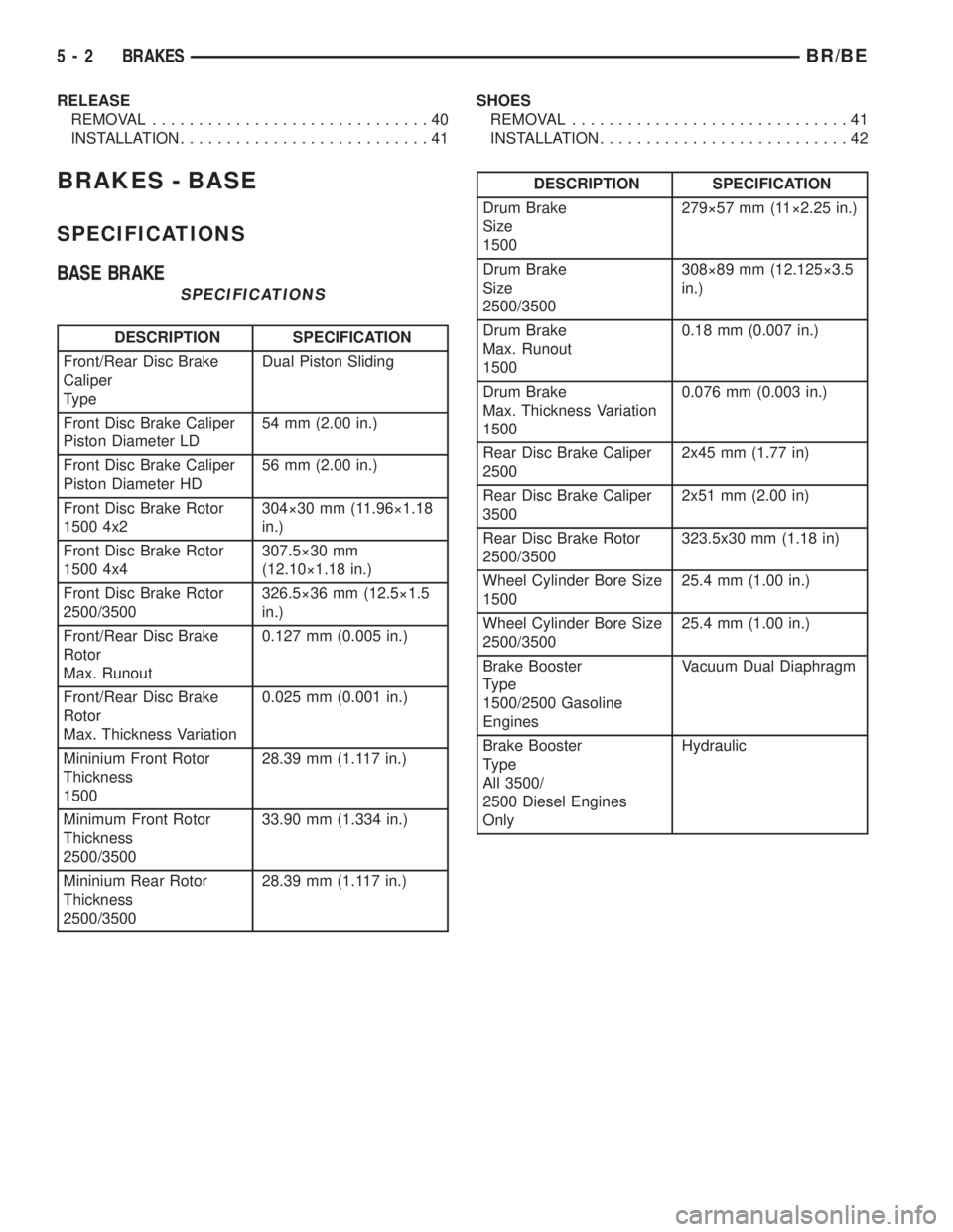
SPECIFICATIONS
BASE BRAKE
SPECIFICATIONS
DESCRIPTION SPECIFICATION
Front/Rear Disc Brake
Caliper
TypeDual Piston Sliding
Front Disc Brake Caliper
Piston Diameter LD54 mm (2.00 in.)
Front Disc Brake Caliper
Piston Diameter HD56 mm (2.00 in.)
Front Disc Brake Rotor
1500 4x2304ý30 mm (11.96ý1.18
in.)
Front Disc Brake Rotor
1500 4x4307.5ý30 mm
(12.10ý1.18 in.)
Front Disc Brake Rotor
2500/3500326.5ý36 mm (12.5ý1.5
in.)
Front/Rear Disc Brake
Rotor
Max. Runout0.127 mm (0.005 in.)
Front/Rear Disc Brake
Rotor
Max. Thickness Variation0.025 mm (0.001 in.)
Mininium Front Rotor
Thickness
150028.39 mm (1.117 in.)
Minimum Front Rotor
Thickness
2500/350033.90 mm (1.334 in.)
Mininium Rear Rotor
Thickness
2500/350028.39 mm (1.117 in.)
DESCRIPTION SPECIFICATION
Drum Brake
Size
1500279ý57 mm (11ý2.25 in.)
Drum Brake
Size
2500/3500308ý89 mm (12.125ý3.5
in.)
Drum Brake
Max. Runout
15000.18 mm (0.007 in.)
Drum Brake
Max. Thickness Variation
15000.076 mm (0.003 in.)
Rear Disc Brake Caliper
25002x45 mm (1.77 in)
Rear Disc Brake Caliper
35002x51 mm (2.00 in)
Rear Disc Brake Rotor
2500/3500323.5x30 mm (1.18 in)
Wheel Cylinder Bore Size
150025.4 mm (1.00 in.)
Wheel Cylinder Bore Size
2500/350025.4 mm (1.00 in.)
Brake Booster
Type
1500/2500 Gasoline
EnginesVacuum Dual Diaphragm
Brake Booster
Type
All 3500/
2500 Diesel Engines
OnlyHydraulic
5 - 2 BRAKESBR/BE
Page 280 of 2889
tube can be used for emergency repair when factory
replacement parts are not readily available.
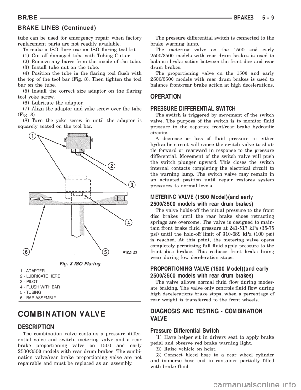
To make a ISO flare use an ISO flaring tool kit.
(1) Cut off damaged tube with Tubing Cutter.
(2) Remove any burrs from the inside of the tube.
(3) Install tube nut on the tube.
(4) Position the tube in the flaring tool flush with
the top of the tool bar (Fig. 3). Then tighten the tool
bar on the tube.
(5) Install the correct size adaptor on the flaring
tool yoke screw.
(6) Lubricate the adaptor.
(7) Align the adaptor and yoke screw over the tube
(Fig. 3).
(8) Turn the yoke screw in until the adaptor is
squarely seated on the tool bar.
COMBINATION VALVE
DESCRIPTION
The combination valve contains a pressure differ-
ential valve and switch, metering valve and a rear
brake proportioning valve on 1500 and early
2500/3500 models with rear drum brakes. The combi-
nation valve/rear brake proportioning valve are not
repairable and must be replaced as an assembly.The pressure differential switch is connected to the
brake warning lamp.
The metering valve on the 1500 and early
2500/3500 models with rear drum brakes is used to
balance brake action between the front disc and rear
drum brakes.
The proportioning valve on the 1500 and early
2500/3500 models with rear drum brakes is used to
balance front-rear brake action at high decelerations.
OPERATION
PRESSURE DIFFERENTIAL SWITCH
The switch is triggered by movement of the switch
valve. The purpose of the switch is to monitor fluid
pressure in the separate front/rear brake hydraulic
circuits.
A decrease or loss of fluid pressure in either
hydraulic circuit will cause the switch valve to shut-
tle forward or rearward in response to the pressure
differential. Movement of the switch valve will push
the switch plunger upward. This closes the switch
internal contacts completing the electrical circuit to
the warning lamp. The switch valve may remain in
an actuated position until repair restores system
pressures to normal levels.
METERING VALVE (1500 Model)(and early
2500/3500 models with rear drum brakes)
The valve holds-off the initial pressure to the front
disc brakes until the rear brake shoes retracting
springs are overcome. The valve is designed to main-
tain front brake fluid pressure at 241-517 kPa (35-75
psi) until the hold-off limit of 310-689 kPa (100 psi)
is reached. At this point, the metering valve opens
completely permitting full fluid apply pressure to the
front disc brakes. This reduces front brake lining
wear during low deceleration stops.
PROPORTIONING VALVE (1500 Model)(and early
2500/3500 models with rear drum brakes)
The valve allows normal fluid flow during moder-
ate braking. The valve only controls fluid flow during
high decelerations brake stops, when a percentage of
rear weight is transferred to the front wheels.
DIAGNOSIS AND TESTING - COMBINATION
VALVE
Pressure Differential Switch
(1) Have helper sit in drivers seat to apply brake
pedal and observe red brake warning light.
(2) Raise vehicle on hoist.
(3) Connect bleed hose to a rear wheel cylinder
and immerse hose end in container partially filled
with brake fluid.
Fig. 3 ISO Flaring
1 - ADAPTER
2 - LUBRICATE HERE
3 - PILOT
4 - FLUSH WITH BAR
5 - TUBING
6 - BAR ASSEMBLY
BR/BEBRAKES 5 - 9
BRAKE LINES (Continued)
Page 304 of 2889
The drum forces both brake shoes to move in the
same direction of rotation. Servo action begins with
the primary brake shoe which begins to wedge (or
wrap) itself against the rotating drum surface. This
force is transmitted equally to the secondary brake
shoe through the adjuster screw and anchor pin. The
net result is that each shoe helps the other exert
extra force against the drum. It is servo action that
creates the wedging (or wrap) effect which produces
increased force on the drum braking surface.
All drum brake assemblies are equipped with a self
adjusting mechanism. The components forming the
mechanism consist of the: adjuster screw, adjuster
lever, actuating lever (11 inch brake), lever return
spring and the adjuster lever spring. The adjuster
lever on the 12 inch brake, is also equipped with a
lever and tension spring.
The adjuster mechanism performs two important
functions. First, is in maintaining proper brake shoe
operating clearance. And second, is to maintain brake
pedal height. The mechanism does so, by adjusting
the shoes in small increments to compensate for lin-
ing wear. The adjustment process is continuous
throughout the useful life of the brake lining.
The adjuster components are all connected to the
secondary brake shoes. Actual adjustment only
occurs during reverse brake stops. Secondary brake
shoe movement (during reverse stops), is what acti-
vates the adjuster components.
In operation, secondary shoe movement causes the
adjuster lever spring to exert pull on the lever. This
pivots the lever away from the adjuster screw teeth.
When the stop is completed and the brakes released,
the adjuster lever pivots back to a normal position. It
is during this return movement of the lever when
adjustment occurs. At this point, the lever comes
back into contact with the adjuster screw teeth as it
moves upward. The lever will then rotate the
adjuster screw one or two teeth as needed for adjust-
ment.
NOTE: The adjustment process requires a complete
stop to actually occur. Rolling stops will NOT acti-
vate the adjuster components. In addition, the
adjuster screws are left and right hand parts and
must NOT be interchanged.
DIAGNOSIS AND TESTING - BRAKE DRUM
The maximum allowable diameter of the drum
braking surface is indicated on the drum outer edge.
Generally, a drum can be machined to a maximum of
1.52 mm (0.060 in.) oversize. Always replace the
drum if machining would cause drum diameter to
exceed the size limit indicated on the drum.
BRAKE DRUM RUNOUT
Measure drum diameter and runout with an accu-
rate gauge. The most accurate method of measure-
ment involves mounting the drum in a brake lathe
and checking variation and runout with a dial indi-
cator.
Variations in drum diameter should not exceed
0.069 mm (0.0028 in.). Drum runout should not
exceed 0.18 mm (0.007 in.) out of round. Machine the
drum if runout or variation exceed these values.
Replace the drum if machining causes the drum to
exceed the maximum allowable diameter.
STANDARD PROCEDURE - BRAKE DRUM
MACHINING
The brake drums can be machined on a drum lathe
when necessary. Initial machining cuts should be lim-
ited to 0.12 - 0.20 mm (0.005 - 0.008 in.) at a time as
heavier feed rates can produce taper and surface
variation. Final finish cuts of 0.025 to 0.038 mm
(0.001 to 0.0015 in.) are recommended and will gen-
erally provide the best surface finish.
Be sure the drum is securely mounted in the lathe
before machining operations. A damper strap should
always be used around the drum to reduce vibration
and avoid chatter marks.
The maximum allowable diameter of the drum
braking surface is stamped or cast into the drum
outer edge.
CAUTION: Replace the drum if machining will cause
the drum to exceed the maximum allowable diame-
ter.
CLEANING
Clean the individual brake components, including
the support plate and wheel cylinder exterior, with a
water dampened cloth or with brake cleaner. Do not
use any other cleaning agents. Remove light rust and
scale from the brake shoe contact pads on the sup-
port plate with fine sandpaper.
INSPECTION
As a general rule, riveted brake shoes should be
replaced when worn to within 0.78 mm (1/32 in.) of
the rivet heads. Bonded lining should be replaced
when worn to a thickness of 1.6 mm (1/16 in.).
Examine the lining contact pattern to determine if
the shoes are bent or the drum is tapered. The lining
should exhibit contact across its entire width. Shoes
exhibiting contact only on one side should be
replaced and the drum checked for runout or taper.
Inspect the adjuster screw assembly. Replace the
assembly if the star wheel or threads are damaged,
or the components are severely rusted or corroded.
BR/BEBRAKES 5 - 33
DRUM (Continued)
Page 320 of 2889
CONDITION POSSIBLE CAUSES CORRECTION
Contact surface of release bearing
damaged.1. Clutch cover incorrect or release
fingers bent or distorted.1. Replace clutch cover and release
bearing.
2. Release bearing defective or
damaged.2. Replace the release bearing.
3. Release bearing misaligned. 3. Check and correct runout of
clutch components. Check front
bearing sleeve for damage/
alignment. Repair as necessary.
Partial engagement of clutch disc.
One side of disc is worn and the
other side is glazed and lightly
worn.1. Clutch pressure plate position
incorrect.1. Replace clutch disc and cover.
2. Clutch cover, spring, or release
fingers bent or distorted.2. Replace clutch disc and cover.
3. Clutch disc damaged or
distorted.2. Replace clutch disc.
4. Clutch misalignment. 4. Check alignment and runout of
flywheel, disc, pressure plate, andùr
clutch housing. Correct as
necessary.
SPECIFICATIONS
SPECIFICATIONS - CLUTCH
TORQUE SPECIFICATIONS
DESCRIPTION N´m Ft. Lbs. In. Lbs.
Nut, slave cylinder 19-26 14-19 170-230
Bolt, clutch cover-5/16 in. 23 17 -
Bolt, clutch cover-3/8 in. 41 30 -
Pivot, release bearing 23 17 -
Screw, fluid reservoir 5 - 40
CLUTCH DISC
DESCRIPTION
The clutch disc friction material is riveted to the
disc hub. The hub bore is splined for installation on
the transmission input shaft. The clutch disc has
cushion springs in the disc hub to dampen disc vibra-
tions during application and release of the clutch.
Various size and design of clutches are used for the
different engine transmission combinations. The cur-
rently used clutches and applications are listed
below.A 281 mm (11 in.) diameter clutch disc is used with
a 3.9L, 5.2L, or 5.9L gas engines (Fig. 4) and (Fig. 5).
A 312.5 mm (12.3 in.) diameter clutch disc is used
with diesel and V10 engines and (Fig. 6).
All the discs have damper springs in the hub. The
281 mm discs have four springs, the 312.5 mm diesel/
V10 disc has nine springs. The damper springs pro-
vide smoother torque transfer and disc engagement.
BR/BECLUTCH 6 - 7
CLUTCH (Continued)
Page 324 of 2889
CLUTCH HOUSING
DIAGNOSIS AND TESTING - CLUTCH HOUSING
Clutch housing alignment is important to proper
clutch operation. The housing maintains alignment
between the crankshaft and transmission input
shaft. Misalignment can cause clutch noise, hard
shifting, incomplete release and chatter. It can also
result in premature wear of the pilot bearing, cover
release fingers and clutch disc. In severe cases, mis-
alignment can also cause premature wear of the
transmission input shaft and front bearing.
Housing misalignment is generally caused by
incorrect seating on the engine or transmission, loose
housing bolts, missing alignment dowels, or housing
damage. Infrequently, misalignment may also be
caused by housing mounting surfaces that are not
completely parallel. Misalignment can be corrected
with shims.
CHECKING RUNOUT
Only the NV4500 clutch housing can be
checked using the following bore and face
runout procedures. The NV3500 and NV5600
clutch housings are an integral part of the
transmission and can only be checked off the
vehicle.
MEASURING CLUTCH HOUSING BORE RUNOUT
(1) Remove the clutch housing and strut.
(2) Remove the clutch cover and disc.
(3) Replace one of the flywheel bolts with an
appropriate size threaded rod that is 10 in. (25.4 cm)
long (Fig. 14). The rod will be used to mount the dial
indicator.(4) Remove the release fork from the clutch hous-
ing.
(5) Reinstall the clutch housing. Tighten the hous-
ing bolts nearest the alignment dowels first.
(6) Mount the dial indicator on the threaded rod
and position the indicator plunger on the surface of
the clutch housing bore (Fig. 15).
(7) Rotate the crankshaft until the indicator
plunger is at the top center of the housing bore. Zero
the indicator at this point.
(8) Rotate the crankshaft and record the indicator
readings at eight points (45É apart) around the bore
(Fig. 15). Repeat the measurement at least twice for
accuracy.
(9) Subtract each reading from the one 180É oppo-
site to determine magnitude and direction of runout.
Refer to (Fig. 16) and following example.
Bore runout example:
0.000 ± (±0.007) = 0.007 in.
+0.002 ± (±0.010) = 0.012 in.
+0.004 ± (±0.005) = 0.009 in.
±0.001 ± (+0.001) = ±0.002 in. (= 0.002 inch)
In the above example, the largest difference is
0.012 in. and is called the total indicator reading
(TIR). This means that the housing bore is offset
from the crankshaft centerline by 0.006 in. (which is
1/2 of 0.012 in.).
Fig. 14 Dial Indicator Mounting Stud Or Rod
1 - 7/16 - 20 THREAD
2 - NUT
3 - STUD OR THREADED ROD
4 - 10 INCHES LONG
Fig. 15 Checking Clutch Housing Bore Runout
1 - MOUNTING STUD OR ROD
2 - DIAL INDICATOR
3 - INDICATOR PLUNGER
4 - CLUTCH HOUSING BORE
BR/BECLUTCH 6 - 11
Page 570 of 2889
DISASSEMBLY
Some of the components for the instrument cluster
used in this vehicle are serviced individually. The
serviced components include: the automatic transmis-
sion gear selector indicator, the incandescent instru-
ment cluster indicator lamp and illumination lamp
bulbs (including the integral bulb holders), the clus-
ter lens and hood unit, and the cluster housing rear
cover. The remaining components are serviced only
as a part of the cluster housing unit, which includes:
the cluster housing, the electronic circuit board unit,
the cluster overlay, the gauges, and the odometer/trip
odometer reset switch button. Following are the pro-
cedures for disassembling the serviced components
from the instrument cluster unit.
WARNING: ON VEHICLES EQUIPPED WITH AIR-
BAGS, DISABLE THE AIRBAG SYSTEM BEFORE
ATTEMPTING ANY STEERING WHEEL, STEERING
COLUMN, OR INSTRUMENT PANEL COMPONENT
DIAGNOSIS OR SERVICE. DISCONNECT AND ISO-
LATE THE BATTERY NEGATIVE (GROUND) CABLE,
THEN WAIT TWO MINUTES FOR THE AIRBAG SYS-
TEM CAPACITOR TO DISCHARGE BEFORE PER-
FORMING FURTHER DIAGNOSIS OR SERVICE. THIS
IS THE ONLY SURE WAY TO DISABLE THE AIRBAG
SYSTEM. FAILURE TO TAKE THE PROPER PRE-
CAUTIONS COULD RESULT IN ACCIDENTAL AIR-
BAG DEPLOYMENT AND POSSIBLE PERSONAL
INJURY.GEAR SELECTOR INDICATOR
(1) Disconnect and isolate the battery negative
cable.
(2) Remove the instrument cluster from the instru-
ment panel. (Refer to 8 - ELECTRICAL/INSTRU-
MENT CLUSTER - REMOVAL).
(3) Remove the steering column opening cover
from the instrument panel. (Refer to 23 - BODY/IN-
STRUMENT PANEL/STEERING COLUMN OPEN-
ING COVER - REMOVAL).
(4) Reach through the instrument panel steering
column opening to access and disengage the loop end
of the gear selector indicator cable from the PRNDL
driver lever on the left side of the steering column
(Fig. 4).
(5) Squeeze the sides of the plastic adjuster and
bracket unit to disengage the tabs that secure it to
the sides of the steering column window.
(6) Remove the gear selector indicator mechanism
and cable unit through the instrument panel cluster
opening.
CLUSTER BULB
This procedure applies to each of the incandescent
cluster illumination lamp or indicator lamp bulb and
bulb holder units. However, the illumination lamps
and the indicator lamps use different bulb and bulb
holder unit sizes. They must never be interchanged.
(1) Disconnect and isolate the battery negative
cable.
(2) Remove the instrument cluster from the instru-
ment panel. (Refer to 8 - ELECTRICAL/INSTRU-
MENT CLUSTER - REMOVAL).
Fig. 3 Gear Selector Indicator Remove/Install
1 - INSTRUMENT CLUSTER
2 - GEAR SELECTOR INDICATOR
3 - SCREW
Fig. 4 Gear Selector Indicator Cable Remove/Install
1 - STEERING COLUMN
2 - CABLE
3 - LOOP END
4 - LEVER
5 - ADJUSTER AND BRACKET
BR/BEINSTRUMENT CLUSTER 8J - 11
INSTRUMENT CLUSTER (Continued)
Page 572 of 2889
ASSEMBLY
WARNING: ON VEHICLES EQUIPPED WITH AIR-
BAGS, DISABLE THE AIRBAG SYSTEM BEFORE
ATTEMPTING ANY STEERING WHEEL, STEERING
COLUMN, OR INSTRUMENT PANEL COMPONENT
DIAGNOSIS OR SERVICE. DISCONNECT AND ISO-
LATE THE BATTERY NEGATIVE (GROUND) CABLE,
THEN WAIT TWO MINUTES FOR THE AIRBAG SYS-
TEM CAPACITOR TO DISCHARGE BEFORE PER-
FORMING FURTHER DIAGNOSIS OR SERVICE. THIS
IS THE ONLY SURE WAY TO DISABLE THE AIRBAG
SYSTEM. FAILURE TO TAKE THE PROPER PRE-
CAUTIONS COULD RESULT IN ACCIDENTAL AIR-
BAG DEPLOYMENT AND POSSIBLE PERSONAL
INJURY.
GEAR SELECTOR INDICATOR
(1) Position the gear selector indicator mechanism
and cable unit into the instrument panel cluster
opening.
(2) Route the cable through the instrument panel
and under the steering column to the PRNDL driver
lever on the left side of the steering column.
(3) Squeeze the sides of the plastic adjuster and
bracket unit and engage the tabs that secure it with
the sides of the steering column window.
(4) Engage the loop end of the gear selector indi-
cator cable onto the PRNDL driver lever on the left
side of the steering column (Fig. 4).
(5) Reinstall the instrument cluster onto the
instrument panel. (Refer to 8 - ELECTRICAL/IN-
STRUMENT CLUSTER - INSTALLATION).
(6) Confirm proper operation of the gear selector
indicator. Calibrate the indicator, if required. (Refer
to 19 - STEERING/COLUMN - INSTALLATION).
(7) Reinstall the steering column opening cover
onto the instrument panel. (Refer to 23 - BODY/IN-
STRUMENT PANEL/STEERING COLUMN OPEN-
ING COVER - INSTALLATION).
(8) Reconnect the battery negative cable.
CLUSTER BULB
This procedure applies to each of the incandescent
cluster illumination lamp or indicator lamp bulb and
bulb holder units. However, the illumination lamps
and the indicator lamps use different bulb and bulb
holder unit sizes. They must never be interchanged.
CAUTION: Be certain that any bulb and bulb holder
unit removed from the cluster electronic circuit
board is reinstalled in the correct position. Always
use the correct bulb size and type for replacement.
An incorrect bulb size or type may overheat and
cause damage to the instrument cluster, the elec-
tronic circuit board and/or the gauges.(1) Insert the bulb and bulb holder unit straight
into the correct bulb mounting hole in the cluster
electronic circuit board (Fig. 5).
(2) With the bulb holder fully seated against the
cluster electronic circuit board, turn the bulb holder
clockwise about sixty degrees to lock it into place.
(3) Reinstall the instrument cluster onto the
instrument panel. (Refer to 8 - ELECTRICAL/IN-
STRUMENT CLUSTER - INSTALLATION).
(4) Reconnect the battery negative cable.
CLUSTER LENS AND HOOD
CAUTION: Do not touch the face of the gauge over-
lay or the back of the cluster lens with your finger.
It will leave a permanent finger print.
(1) Align the cluster lens and hood unit with the
cluster housing. Be certain that the odometer/trip
odometer switch button is installed through the
clearance hole in the lens (Fig. 6).
(2) Install and tighten the seven screws that
secure the lens and hood unit to the cluster housing.
Tighten the screws to 2.2 N´m (20 in. lbs.).
(3) Reinstall the instrument cluster onto the
instrument panel. (Refer to 8 - ELECTRICAL/IN-
STRUMENT CLUSTER - INSTALLATION).
(4) Reconnect the battery negative cable.
CLUSTER HOUSING REAR COVER
(1) Position the rear cover onto the back of the
cluster housing (Fig. 7).
(2) Install and tighten the six screws that secure
the rear cover to the back of the cluster housing.
Tighten the screws to 2.2 N´m (20 in. lbs.).
(3) Reinstall the instrument cluster onto the
instrument panel. (Refer to 8 - ELECTRICAL/IN-
STRUMENT CLUSTER - INSTALLATION).
(4) Reconnect the battery negative cable.
CLUSTER HOUSING
(1) Assemble the rear cover onto the cluster hous-
ing. Refer to CLUSTER HOUSING REAR COVER .
(2) Assemble the lens and hood unit onto the clus-
ter housing. Refer to CLUSTER LENS AND HOOD .
(3) Reinstall the instrument cluster onto the
instrument panel. (Refer to 8 - ELECTRICAL/IN-
STRUMENT CLUSTER - INSTALLATION).
(4) Reconnect the battery negative cable.
BR/BEINSTRUMENT CLUSTER 8J - 13
INSTRUMENT CLUSTER (Continued)
Page 698 of 2889
INSTALLATION
WARNING: DISABLE THE AIRBAG SYSTEM
BEFORE ATTEMPTING ANY STEERING WHEEL,
STEERING COLUMN, OR INSTRUMENT PANEL
COMPONENT DIAGNOSIS OR SERVICE. DISCON-
NECT AND ISOLATE THE BATTERY NEGATIVE
(GROUND) CABLE, THEN WAIT TWO MINUTES FOR
THE AIRBAG SYSTEM CAPACITOR TO DISCHARGE
BEFORE PERFORMING FURTHER DIAGNOSIS OR
SERVICE. THIS IS THE ONLY SURE WAY TO DIS-
ABLE THE AIRBAG SYSTEM. FAILURE TO TAKE
THE PROPER PRECAUTIONS COULD RESULT IN
ACCIDENTAL AIRBAG DEPLOYMENT AND POSSI-
BLE PERSONAL INJURY.
WARNING: WHEN REMOVING A DEPLOYED AIR-
BAG, RUBBER GLOVES, EYE PROTECTION, AND A
LONG-SLEEVED SHIRT SHOULD BE WORN. THERE
MAY BE DEPOSITS ON THE AIRBAG UNIT AND
OTHER INTERIOR SURFACES. IN LARGE DOSES,
THESE DEPOSITS MAY CAUSE IRRITATION TO THE
SKIN AND EYES.
WARNING: USE EXTREME CARE TO PREVENT ANY
FOREIGN MATERIAL FROM ENTERING THE PAS-
SENGER AIRBAG, OR BECOMING ENTRAPPED
BETWEEN THE PASSENGER AIRBAG CUSHION
AND THE PASSENGER AIRBAG DOOR. FAILURE TO
OBSERVE THIS WARNING COULD RESULT IN
OCCUPANT INJURIES UPON AIRBAG DEPLOY-
MENT.
WARNING: THE PASSENGER AIRBAG DOOR MUST
NEVER BE PAINTED. REPLACEMENT PASSENGER
AIRBAG DOORS ARE SERVICED IN THE ORIGINAL
COLORS. PAINT MAY CHANGE THE WAY IN WHICH
THE MATERIAL OF THE AIRBAG DOOR RESPONDS
TO AN AIRBAG DEPLOYMENT. FAILURE TO
OBSERVE THIS WARNING COULD RESULT IN
OCCUPANT INJURIES UPON AIRBAG DEPLOY-
MENT.
(1) Carefully inspect the five receptacle slots
around the top and sides of the passenger airbag
door opening of the instrument panel top cover.
Remove any of the small metal airbag door snap
retainers that did not remain on the molded airbag
door tabs during the removal procedure.
(2) If the removed passenger airbag module is
being reinstalled, install the metal snap retainers
recovered in Step 1onto the proper airbag door tabs.
Each of the five molded airbag door tabs must have a
snap retainer on it before it is installed in the instru-ment panel. New replacement passenger airbags
come with new airbag door snap retainers installed.
(3) Carefully position the passenger airbag onto
the instrument panel.
(4) Align the five tabs and retainers on the upper
edge and sides of the passenger airbag door with the
receptacles in the instrument panel top cover.
(5) Using hand pressure, press firmly on the pas-
senger airbag door over each of the tab and retainer
locations until each of them is fully engaged in its
receptacle. Be certain that each of the metal snap
retainers is in position on the airbag door tabs.
(6) Install and tighten the five screws that secure
the passenger airbag front and rear mounting brack-
ets to the instrument panel (Fig. 18). Tighten the
screws to 9 N´m (80 in. lbs.).
(7) Install and tighten the four screws that secure
the two plastic support brackets of the passenger air-
bag door panel outlet housing to the glove box open-
ing upper reinforcement. Tighten the screws to 2.2
N´m (20 in. lbs.).
(8) Reach through and above the glove box opening
to access and reconnect the passenger airbag pigtail
wire connector to the instrument panel wire harness
connector (Fig. 17). Be certain that the passenger air-
bag pigtail wire connector is fully engaged with and
latched to the instrument panel wire harness connec-
tor.
(9) Reinstall the glove box opening upper trim onto
the instrument panel. (Refer to 23 - BODY/INSTRU-
MENT PANEL/GLOVE BOX OPENING UPPER
TRIM - INSTALLATION).
(10) Reinstall the glove box onto the instrument
panel. (Refer to 23 - BODY/INSTRUMENT PANEL/
GLOVE BOX - INSTALLATION).
(11) Do not reconnect the battery negative cable at
this time. The airbag system verification test proce-
dure should be performed following service of any
airbag system component. (Refer to 8 - ELECTRI-
CAL/RESTRAINTS - STANDARD PROCEDURE -
VERIFICATION TEST).
PASSENGER AIRBAG ON/OFF
SWITCH
DESCRIPTION
The passenger airbag on-off switch is standard
equipment on this model when it is not equipped
with a full size rear seat. This switch is a single pole,
single throw switch with a single integral red Light-
Emitting Diode (LED), and a non-coded key cylinder-
type actuator. The switch is located in the upper
right corner of instrument panel cluster bezel, near
the center of instrument panel to make the Off indi-
cator visible to all front seat occupants. When the
BR/BERESTRAINTS 8O - 23
PASSENGER AIRBAG (Continued)