park assist DODGE RAM 2001 Service User Guide
[x] Cancel search | Manufacturer: DODGE, Model Year: 2001, Model line: RAM, Model: DODGE RAM 2001Pages: 2889, PDF Size: 68.07 MB
Page 548 of 2889
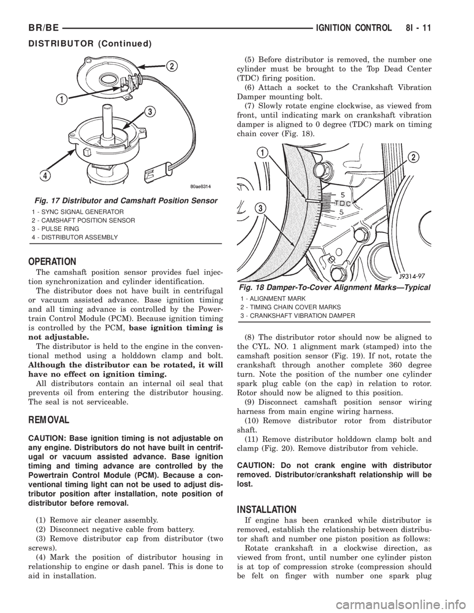
OPERATION
The camshaft position sensor provides fuel injec-
tion synchronization and cylinder identification.
The distributor does not have built in centrifugal
or vacuum assisted advance. Base ignition timing
and all timing advance is controlled by the Power-
train Control Module (PCM). Because ignition timing
is controlled by the PCM,base ignition timing is
not adjustable.
The distributor is held to the engine in the conven-
tional method using a holddown clamp and bolt.
Although the distributor can be rotated, it will
have no effect on ignition timing.
All distributors contain an internal oil seal that
prevents oil from entering the distributor housing.
The seal is not serviceable.
REMOVAL
CAUTION: Base ignition timing is not adjustable on
any engine. Distributors do not have built in centrif-
ugal or vacuum assisted advance. Base ignition
timing and timing advance are controlled by the
Powertrain Control Module (PCM). Because a con-
ventional timing light can not be used to adjust dis-
tributor position after installation, note position of
distributor before removal.
(1) Remove air cleaner assembly.
(2) Disconnect negative cable from battery.
(3) Remove distributor cap from distributor (two
screws).
(4) Mark the position of distributor housing in
relationship to engine or dash panel. This is done to
aid in installation.(5) Before distributor is removed, the number one
cylinder must be brought to the Top Dead Center
(TDC) firing position.
(6) Attach a socket to the Crankshaft Vibration
Damper mounting bolt.
(7) Slowly rotate engine clockwise, as viewed from
front, until indicating mark on crankshaft vibration
damper is aligned to 0 degree (TDC) mark on timing
chain cover (Fig. 18).
(8) The distributor rotor should now be aligned to
the CYL. NO. 1 alignment mark (stamped) into the
camshaft position sensor (Fig. 19). If not, rotate the
crankshaft through another complete 360 degree
turn. Note the position of the number one cylinder
spark plug cable (on the cap) in relation to rotor.
Rotor should now be aligned to this position.
(9) Disconnect camshaft position sensor wiring
harness from main engine wiring harness.
(10) Remove distributor rotor from distributor
shaft.
(11) Remove distributor holddown clamp bolt and
clamp (Fig. 20). Remove distributor from vehicle.
CAUTION: Do not crank engine with distributor
removed. Distributor/crankshaft relationship will be
lost.
INSTALLATION
If engine has been cranked while distributor is
removed, establish the relationship between distribu-
tor shaft and number one piston position as follows:
Rotate crankshaft in a clockwise direction, as
viewed from front, until number one cylinder piston
is at top of compression stroke (compression should
be felt on finger with number one spark plug
Fig. 17 Distributor and Camshaft Position Sensor
1 - SYNC SIGNAL GENERATOR
2 - CAMSHAFT POSITION SENSOR
3 - PULSE RING
4 - DISTRIBUTOR ASSEMBLY
Fig. 18 Damper-To-Cover Alignment MarksÐTypical
1 - ALIGNMENT MARK
2 - TIMING CHAIN COVER MARKS
3 - CRANKSHAFT VIBRATION DAMPER
BR/BEIGNITION CONTROL 8I - 11
DISTRIBUTOR (Continued)
Page 2575 of 2889
DIAGNOSIS AND TESTING ± WATER LEAKS
Water leaks can be caused by poor sealing,
improper body component alignment, body seam
porosity, missing plugs, or blocked drain holes. Cen-
trifugal and gravitational force can cause water to
drip from a location away from the actual leak point,
making leak detection difficult. All body sealing
points should be water tight in normal wet-driving
conditions. Water flowing downward from the front of
the vehicle should not enter the passenger or luggage
compartment. Moving sealing surfaces will not
always seal water tight under all conditions. At
times, side glass or door seals will allow water to
enter the passenger compartment during high pres-
sure washing or hard driving rain (severe) condi-
tions. Overcompensating on door or glass
adjustments to stop a water leak that occurs under
severe conditions can cause premature seal wear and
excessive closing or latching effort. After completing
a repair, water test vehicle to verify leak has stopped
before returning vehicle to use.
VISUAL INSPECTION BEFORE WATER LEAK TESTS
Verify that floor and body plugs are in place, body
drains are clear, and body components are properly
aligned and sealed. If component alignment or seal-
ing is necessary, refer to the appropriate section of
this group for proper procedures.
WATER LEAK TESTS
WARNING: DO NOT USE ELECTRIC SHOP LIGHTS
OR TOOLS IN WATER TEST AREA. PERSONAL
INJURY CAN RESULT.
When the conditions causing a water leak have
been determined, simulate the conditions as closely
as possible.
²If a leak occurs with the vehicle parked in a
steady light rain, flood the leak area with an open-
ended garden hose.
²If a leak occurs while driving at highway speeds
in a steady rain, test the leak area with a reasonable
velocity stream or fan spray of water. Direct the
spray in a direction comparable to actual conditions.
²If a leak occurs when the vehicle is parked on an
incline, hoist the end or side of the vehicle to simu-
late this condition. This method can be used when
the leak occurs when the vehicle accelerates, stops or
turns. If the leak occurs on acceleration, hoist the
front of the vehicle. If the leak occurs when braking,
hoist the back of the vehicle. If the leak occurs on left
turns, hoist the left side of the vehicle. If the leak
occurs on right turns, hoist the right side of the vehi-
cle. For hoisting recommendations refer to Group 0,
Lubrication and Maintenance, General Information
section.
WATER LEAK DETECTION
To detect a water leak point-of-entry, do a water
test and watch for water tracks or droplets forming
on the inside of the vehicle. If necessary, remove inte-
rior trim covers or panels to gain visual access to the
leak area. If the hose cannot be positioned without
being held, have someone help do the water test.
Some water leaks must be tested for a considerable
length of time to become apparent. When a leak
appears, find the highest point of the water track or
drop. The highest point usually will show the point of
entry. After leak point has been found, repair the
leak and water test to verify that the leak has
stopped.
Locating the entry point of water that is leaking
into a cavity between panels can be difficult. The
trapped water may splash or run from the cavity,
often at a distance from the entry point. Most water
leaks of this type become apparent after accelerating,
stopping, turning, or when on an incline.
MIRROR INSPECTION METHOD
When a leak point area is visually obstructed, use
a suitable mirror to gain visual access. A mirror can
also be used to deflect light to a limited-access area
to assist in locating a leak point.
BRIGHT LIGHT LEAK TEST METHOD
Some water leaks in the luggage compartment can
be detected without water testing. Position the vehi-
cle in a brightly lit area. From inside the darkened
luggage compartment inspect around seals and body
seams. If necessary, have a helper direct a drop light
over the suspected leak areas around the luggage
compartment. If light is visible through a normally
sealed location, water could enter through the open-
ing.
PRESSURIZED LEAK TEST METHOD
When a water leak into the passenger compart-
ment cannot be detected by water testing, pressurize
the passenger compartment and soap test exterior of
the vehicle. To pressurize the passenger compart-
ment, close all doors and windows, start engine, and
set heater control to high blower in HEAT position. If
engine can not be started, connect a charger to the
battery to ensure adequate voltage to the blower.
With interior pressurized, apply dish detergent solu-
tion to suspected leak area on the exterior of the
vehicle. Apply detergent solution with spray device or
soft bristle brush. If soap bubbles occur at a body
seam, joint, seal or gasket, the leak entry point could
be at that location.
23 - 2 BODYBR/BE
BODY (Continued)
Page 2679 of 2889
REMOVAL
WARNING: ON VEHICLES EQUIPPED WITH AIR-
BAGS, DISABLE THE AIRBAG SYSTEM BEFORE
ATTEMPTING ANY STEERING WHEEL, STEERING
COLUMN, OR INSTRUMENT PANEL COMPONENT
DIAGNOSIS OR SERVICE. DISCONNECT AND ISO-
LATE THE BATTERY NEGATIVE (GROUND) CABLE,
THEN WAIT TWO MINUTES FOR THE AIRBAG SYS-
TEM CAPACITOR TO DISCHARGE BEFORE PER-
FORMING FURTHER DIAGNOSIS OR SERVICE. THIS
IS THE ONLY SURE WAY TO DISABLE THE AIRBAG
SYSTEM. FAILURE TO TAKE THE PROPER PRE-
CAUTIONS COULD RESULT IN ACCIDENTAL AIR-
BAG DEPLOYMENT AND POSSIBLE PERSONAL
INJURY.
NOTE: Before starting this procedure, be certain to
turn the steering wheel until the front wheels are in
the straight-ahead position.
(1) Disconnect and isolate the battery negative
cable.
(2) Remove the Airbag Control Module (ACM) and
bracket from the floor panel transmission tunnel.
(Refer to 8 - ELECTRICAL/RESTRAINTS/AIRBAG
CONTROL MODULE - REMOVAL).
(3) Remove the trim from the left and right cowl
side inner panels. (Refer to 23 - BODY/INTERIOR/
COWL TRIM COVER - REMOVAL).
(4) Remove the steering column opening cover
from the instrument panel. (Refer to 23 - BODY/IN-
STRUMENT PANEL/STEERING COLUMN OPEN-
ING COVER - REMOVAL).
(5) Remove the two screws that secure the inside
hood latch release handle to the instrument panel
lower reinforcement and lower the release handle to
the floor.
(6) Disconnect the clockspring pigtail wire connec-
tor from the instrument panel wire harness connec-
tor located on the instrument panel lower
reinforcement.
(7) If the vehicle is so equipped, disconnect the
overdrive lockout switch pigtail wire connector from
the instrument panel wire harness connector near
the instrument panel lower reinforcement.
(8) Remove the steering column from the vehicle,
but do not remove the driver airbag, the steering
wheel, or the switches from the column. Be certain
that the steering wheel is locked and secured from
rotation to prevent the loss of clockspring centering.
(Refer to 19 - STEERING/COLUMN - REMOVAL).
(9) From under the driver side of the instrument
panel, perform the following:
(a) Disengage the park brake release handle
linkage rod from the park brake mechanism on theleft cowl side inner panel. (Refer to 5 - BRAKES/
PARKING BRAKE/RELEASE - REMOVAL).
(b) Disconnect the instrument panel wire har-
ness connector from the park brake switch on the
park brake mechanism.
(c) Disconnect the three connectors (one from the
body wire harness, and two from the headlamp and
dash wire harness) from the three connector recep-
tacles located closest to the dash panel on the back
of the Junction Block (JB).
(d) Remove the screw from the center of the
headlamp and dash wire harness to instrument
panel wire harness bulkhead connector and discon-
nect the connector.
(e) Disconnect the instrument panel wire har-
ness to door wire harness connector located directly
below the instrument panel wire harness to head-
lamp and dash wire harness bulkhead connector.
(f) If the vehicle is equipped with the Infinity
sound system option, disconnect the Infinity wire
harness connector from the instrument panel wire
harness connector that is secured to the outboard
side of the instrument panel wire harness to head-
lamp and dash wire harness bulkhead connector.
(g) Disconnect the instrument panel wire har-
ness connector from the stop lamp switch.
(h) Disconnect the heater-A/C housing vacuum
harness connector from the heater-A/C control vac-
uum harness connector located near the left end of
the heater-A/C housing.
(10) From under the passenger side of the instru-
ment panel, disconnect the two halves of the radio
antenna coaxial cable connector.
(11) Loosen the right and left instrument panel
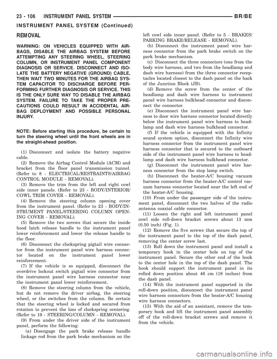
cowl side roll-down bracket screws about 13 mm
(0.50 inch) (Fig. 1).
(12) Remove the five screws that secure the top of
the instrument panel to the top of the dash panel,
removing the center screw last.
(13) Roll down the instrument panel and install a
temporary hook in the center hole on top of the
instrument panel. Secure the other end of the hook
to the center hole in the top of the dash panel. The
hook should support the instrument panel in its
rolled down position about 46 cm (18 inches) from
the dash panel.
(14) With the instrument panel supported in the
roll-down position, disconnect the instrument panel
wire harness connectors from the heater-A/C housing
wire harness connectors.
(15) With the aid of an assistant, remove the tem-
porary hook and lift the instrument panel assembly
off of the roll-down bracket screws and remove it
from the vehicle.
23 - 106 INSTRUMENT PANEL SYSTEMBR/BE
INSTRUMENT PANEL SYSTEM (Continued)
Page 2680 of 2889
INSTALLATION
WARNING: ON VEHICLES EQUIPPED WITH AIR-
BAGS, DISABLE THE AIRBAG SYSTEM BEFORE
ATTEMPTING ANY STEERING WHEEL, STEERING
COLUMN, OR INSTRUMENT PANEL COMPONENT
DIAGNOSIS OR SERVICE. DISCONNECT AND ISO-
LATE THE BATTERY NEGATIVE (GROUND) CABLE,
THEN WAIT TWO MINUTES FOR THE AIRBAG SYS-
TEM CAPACITOR TO DISCHARGE BEFORE PER-
FORMING FURTHER DIAGNOSIS OR SERVICE. THIS
IS THE ONLY SURE WAY TO DISABLE THE AIRBAG
SYSTEM. FAILURE TO TAKE THE PROPER PRE-
CAUTIONS COULD RESULT IN ACCIDENTAL AIR-
BAG DEPLOYMENT AND POSSIBLE PERSONAL
INJURY.
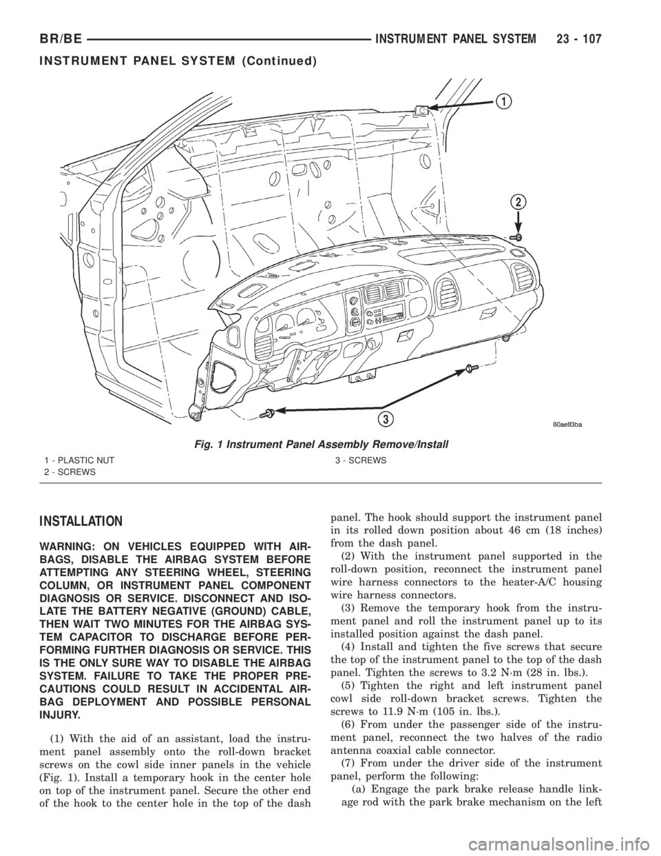
(1) With the aid of an assistant, load the instru-
ment panel assembly onto the roll-down bracket
screws on the cowl side inner panels in the vehicle
(Fig. 1). Install a temporary hook in the center hole
on top of the instrument panel. Secure the other end
of the hook to the center hole in the top of the dashpanel. The hook should support the instrument panel
in its rolled down position about 46 cm (18 inches)
from the dash panel.
(2) With the instrument panel supported in the
roll-down position, reconnect the instrument panel
wire harness connectors to the heater-A/C housing
wire harness connectors.
(3) Remove the temporary hook from the instru-
ment panel and roll the instrument panel up to its
installed position against the dash panel.
(4) Install and tighten the five screws that secure
the top of the instrument panel to the top of the dash
panel. Tighten the screws to 3.2 N´m (28 in. lbs.).
(5) Tighten the right and left instrument panel
cowl side roll-down bracket screws. Tighten the
screws to 11.9 N´m (105 in. lbs.).
(6) From under the passenger side of the instru-
ment panel, reconnect the two halves of the radio
antenna coaxial cable connector.
(7) From under the driver side of the instrument
panel, perform the following:
(a) Engage the park brake release handle link-
age rod with the park brake mechanism on the left
Fig. 1 Instrument Panel Assembly Remove/Install
1 - PLASTIC NUT
2 - SCREWS3 - SCREWS
BR/BEINSTRUMENT PANEL SYSTEM 23 - 107
INSTRUMENT PANEL SYSTEM (Continued)
Page 2810 of 2889
FUEL PRESSURE
The fuel pressure regulator controls fuel system
pressure. The PCM cannot detect a clogged fuel
pump inlet filter, clogged in-line fuel filter, or a
pinched fuel supply or return line. However, these
could result in a rich or lean condition causing the
PCM to store an oxygen sensor or fuel system diag-
nostic trouble code.
SECONDARY IGNITION CIRCUIT
The PCM cannot detect an inoperative ignition coil,
fouled or worn spark plugs, ignition cross firing, or
open spark plug cables.
CYLINDER COMPRESSION
The PCM cannot detect uneven, low, or high engine
cylinder compression.
EXHAUST SYSTEM
The PCM cannot detect a plugged, restricted or
leaking exhaust system, although it may set a fuel
system fault.
FUEL INJECTOR MECHANICAL MALFUNCTIONS
The PCM cannot determine if a fuel injector is
clogged, the needle is sticking or if the wrong injector
is installed. However, these could result in a rich or
lean condition causing the PCM to store a diagnostic
trouble code for either misfire, an oxygen sensor, or
the fuel system.
EXCESSIVE OIL CONSUMPTION
Although the PCM monitors engine exhaust oxygen
content when the system is in closed loop, it cannot
determine excessive oil consumption.
THROTTLE BODY AIR FLOW
The PCM cannot detect a clogged or restricted air
cleaner inlet or filter element.
VACUUM ASSIST
The PCM cannot detect leaks or restrictions in the
vacuum circuits of vacuum assisted engine control
system devices. However, these could cause the PCM
to store a MAP sensor diagnostic trouble code and
cause a high idle condition.
PCM SYSTEM GROUND
The PCM cannot determine a poor system ground.
However, one or more diagnostic trouble codes may
be generated as a result of this condition. The mod-
ule should be mounted to the body at all times, also
during diagnostic.
PCM CONNECTOR ENGAGEMENT
The PCM may not be able to determine spread or
damaged connector pins. However, it might storediagnostic trouble codes as a result of spread connec-
tor pins.
OPERATION - NON-MONITORED CIRCUITS -
DIESEL
The PCM and/or the ECM will not monitor certain
malfunctioning circuits or components that could
cause driveability problems. Also, a Diagnostic Trou-
ble Code (DTC) might not be stored for these mal-
functions. However, problems with these circuits or
components may cause the PCM/ECM to store DTC's
for other circuits or components.EXAMPLES:A cyl-
inder with low compression will not set a DTC
directly, but may cause an engine misfire. This in
turn may cause the ECM to set a DTC for an engine
misfire. Or, a dirty or plugged air filter will not set a
DTC directly, but may cause lack of turbocharger
boost. This in turn may cause the ECM to set a DTC
for a boost pressure malfunction.
FUEL PRESSURE
Primary fuel pressure from the fuel tank to the
fuel injection pump is supplied by the low-pressure
fuel transfer pump. High-pressure to the fuel injec-
tors is supplied by the fuel injection pump. The ECM
cannot detect actual fuel pressure, a clogged fuel fil-
ter, clogged fuel screen, or a pinched fuel supply or
return line. However, a DTC may be set due to an
engine misfire.
CYLINDER COMPRESSION
The ECM cannot detect uneven, low, or high
engine cylinder compression. However, these could
result in a possible misfire which may set a DTC.
EXHAUST SYSTEM
The ECM cannot detect a plugged, restricted or
leaking exhaust system. However, DTC's may be set
for engine misfire, high intake manifold temperature,
high engine coolant temperature, turbocharger over-
boost or turbocharger underboost.
FUEL INJECTOR MECHANICAL MALFUNCTIONS
The ECM cannot determine if a fuel injector is
clogged, the needle is sticking or if the wrong injector
is installed. However, these could result in a possible
misfire which may set a DTC.
EXCESSIVE OIL CONSUMPTION
The ECM cannot determine excessive oil consump-
tion. However, if excess oil consumption is high
enough, it could result in a possible engine misfire
which may set a DTC.
BR/BEEMISSIONS CONTROL 25 - 23
EMISSIONS CONTROL (Continued)
Page 2840 of 2889
ROAD TEST
DESCRIPTION - ROAD TEST INSPECTION
The following items must be inspected during the
road test portion of the new vehicle inspection.
²Check neutral safety switch operation
²Check operation of shift/clutch interlock system
²Check operation of gauges and warning lights
²Check horn operation
²Check operation of turn signals and emergency
flashers
²Check all mirror adjustments, including day/
night function
²Check windshield wipers for proper wipe pattern
and intermittent mode (if equipped)
²Check washer spray pattern
²Check heater, defroster and air conditioning for
proper operation
²Check that the fan operates quietly
²Check the rear window defroster (if equipped)
²Leave air selection lever in the fresh air position
²Check the rear heater and air conditioning for
proper operation
²Check the rear air register locations
²Check that the indicator lamps operate properly
²Check the operation of the radio, cassette and/or
compact disc player, and that sound quality is good
²Ensure that the clock displays the correct time
²Check that the trip computer/maintenance
reminder operates in all modes
²Check all speed control functions
²Check the service brakes to ensure that they
stop the vehicle in a straight line, without noise,
shudder or vibration
²Check the brake warning light
²Check the parking brake operation
²Check the engine's performance
²Check the transmission's performance for
smooth, quiet operation. If the vehicle is a 4x4, check
that the transfer case shifts easily among all ranges
²Check Autostick function (if equipped)
²Check the vehicle's steering and handling
²The steering wheel should be centered when
traveling in a straight line
²The vehicle should not pull or vibrate
²Check for squeaks, rattles and wind noise
²Check any other vehicle aspects you believe are
important, but that may not be included on the New
Vehicle Preparation Form
²Fill fuel tank with specified grade of fuel
INSPECTION - FUEL
Fill fuel tank with specified grade of gasoline (reg-
ular, midgrade or premium).
INSPECTION - OTHER
As part of DaimlerChrysler's Customer One philos-
ophy, the ªOtherº blank is provided on the New Vehi-
cle Preparation Form. This is designed to encourage
you to check any aspects of vehicle operation that
you believe are important to your customers, but that
do not appear elsewhere on the form.
INSPECTION - SQUEAKS, RATTLES AND WIND
NOISE
(1) Make sure that the instrument panel, glove
box, seats, steering wheel and column are free from
squeaks and rattles. Tighten any obvious loose fas-
teners.
(2) Check that the windows and doors are free
from squeaks, rattles and wind noise.
(3) Check that the vehicle exterior is free from
squeaks, rattles and noise, front and rear.
(4) Make sure that all interior panels are free from
squeaks and rattles.
INSPECTION - STEERING AND HANDLING
(1) Check that the power assist works properly (if
equipped). Steering should not require excessive
effort.
(2) Make sure the steering wheel does not vibrate
at idle or road speed.
(3) Ensure that the steering wheel is centered
when traveling straight ahead.
(4) Check that the vehicle does not drift to one
side.
(5) Make sure that the vehicle does not vibrate/
shake.
INSPECTION - TRANSMISSION/TRANSFER
CASE
AUTOMATIC TRANSMISSION
(1) Make sure that the park lock holds the vehicle
With the vehicle on a grade, put automatic trans-
mission in PARK and slowly release the service
brake to see if park lock holds. If it does not hold, the
transmission requires further service.
(2) Make sure shift lever operates easily/ smoothly
(Fig. 36).
Check for smooth shifting. Check for proper
upshifting and downshifting.
MANUAL TRANSMISSION
(1) Check that the shifter operates easily (Fig. 38).
(2) Make sure that the clutch operates smoothly
(Fig. 37).
(3) Look for proper synchronization.
The gears should not grind.
BR/BENEW VEHICLE PREPARATION 30 - 15
Page 2863 of 2889
FUEL TRANSFER PUMP - OPERATION....14-79
FUEL TRANSFER PUMP - REMOVAL......14-83
FUEL TRANSFER PUMP PRESSURE -
DIAGNOSIS AND TESTING.............14-80
FUSE - DESCRIPTION, GENERATOR
CARTRIDGE.......................8W-97-4
FUSE - DESCRIPTION, IOD...........8W-97-4
FUSE - INSTALLATION, GENERATOR
CARTRIDGE.......................8W-97-4
FUSE - INSTALLATION, IOD..........8W-97-5
FUSE - OPERATION, GENERATOR
CARTRIDGE.......................8W-97-4
FUSE - OPERATION, IOD.............8W-97-5
FUSE - REMOVAL, GENERATOR
CARTRIDGE.......................8W-97-4
FUSE - REMOVAL, IOD..............8W-97-5
FUSES POWERING SEVERAL LOADS -
STANDARD PROCEDURE, TESTING
FOR SHORT TO GROUND ON.........8W-01-7
GAP AND FLUSH MEASUREMENTS,
SPECIFICATIONS - BODY...............23-56
GAS ENGINE - DIAGNOSIS AND TESTING . . 11-4
GAS ENGINE - DIAGNOSIS AND
TESTING, COOLING SYSTEM.............7-7
GAS ENGINES - DESCRIPTION,
COMPONENT MONITORS..............25-18
GAS ENGINES - DESCRIPTION, FUEL
REQUIREMENTS.......................0-1
GAS ENGINES - INSTALLATION..........8P-4
GAS ENGINES - OPERATION............25-18
GAS ENGINES - OPERATION, NON-
MONITORED CIRCUITS................25-22
GAS ENGINES - OPERATION, PCM.......8E-17
GAS ENGINES - REMOVAL..............8P-4
GAS ENGINES - SPECIFICATIONS, FUEL
SYSTEM PRESSURE...................14-4
GAS FUEL INJECTION - SPECIFICATIONS,
TORQUE............................14-35
GASKET - DESCRIPTION, CYLINDER
COVER..............................9-79
GASKET - DESCRIPTION, CYLINDER
HEAD COVER.........................9-22
GASKET - OPERATION, CYLINDER HEAD
COVER..............................9-22
GASKET FAILURE - DIAGNOSIS AND
TESTING, CYLINDER HEAD . . . 9-136,9-191,9-22,
9-79
GASKETS & SEALERS - STANDARD
PROCEDURE, FORM-IN-PLACE.....9-11,9-125,
9-180,9-237,9-68
GASOLINE - NEGATIVE CABLE
INSTALLATION.......................8F-24
GASOLINE - NEGATIVE CABLE REMOVAL . . 8F-23
GASOLINE - POSITIVE CABLE
INSTALLATION.......................8F-23
GASOLINE - POSITIVE CABLE REMOVAL . . 8F-23
GASOLINE ENGINE - INSTALLATION......19-35
GASOLINE ENGINE - REMOVAL.........19-33
GAUGE - DESCRIPTION, ENGINE
TEMPERATURE......................8J-19
GAUGE - DESCRIPTION, FUEL...........8J-20
GAUGE - DESCRIPTION, OIL PRESSURE . . 8J-25
GAUGE - DESCRIPTION, VOLTAGE.......8J-33
GAUGE - OPERATION, ENGINE
TEMPERATURE......................8J-19
GAUGE - OPERATION, FUEL............8J-20
GAUGE - OPERATION, OIL PRESSURE....8J-26
GAUGE - OPERATION, VOLTAGE.........8J-34
GAUGE SENDING UNIT - DIAGNOSIS
AND TESTING, FUEL...................14-8
GAUGES - DIAGNOSIS AND TESTING,
PRESSURE..........................22-7
GAUGES INDICATOR - DESCRIPTION,
CHECK.............................8J-17
GAUGES INDICATOR - OPERATION,
CHECK.............................8J-17
GAUGES/WARNING LIGHTS -
INSPECTION........................30-19
GEAR - ADJUSTMENTS................19-16
GEAR - DESCRIPTION.................19-14
GEAR - INSTALLATION................19-16
GEAR - INSTALLATION, PINION
GEAR/RING
......................3-42,3-74
GEAR - OPERATION
...................19-14
GEAR - REMOVAL
....................19-16
GEAR - REMOVAL, PINION GEAR/RING
....3-40,
3-72
GEAR HOUSING - INSTALLATION
........9-305GEAR HOUSING - REMOVAL............9-304
GEAR HOUSING COVER - INSTALLATION . . 9-307
GEAR HOUSING COVER - REMOVAL.....9-306
GEAR HOUSING PLUG - INSTALLATION,
STEERING..........................19-27
GEAR HOUSING PLUG - REMOVAL,
STEERING..........................19-27
GEAR LEAKAGE - DIAGNOSIS AND
TESTING, POWER STEERING...........19-14
GEAR SELECTOR INDICATOR -
DESCRIPTION.......................8J-21
GEAR SELECTOR INDICATOR -
OPERATION.........................8J-21
GEAR SHIFT LEVER - INSTALLATION.....19-13
GEAR SHIFT LEVER - REMOVAL.........19-13
GEAR, SPECIAL TOOLS - POWER
STEERING..........................19-20
GEAR, SPECIFICATIONS - POWER
STEERING..........................19-19
GEAR/RING GEAR - INSTALLATION,
PINION.........................3-42,3-74
GEAR/RING GEAR - REMOVAL, PINION....3-40,
3-72
GEAR/RING GEAR/TONE RING -
INSTALLATION, PINION . 3-105,3-137,3-166,3-195
GEAR/RING GEAR/TONE RING -
REMOVAL, PINION....3-103,3-135,3-165,3-193
GEAR/TONE RING - INSTALLATION,
PINION GEAR/RING....3-105,3-137,3-166,3-195
GEAR/TONE RING - REMOVAL, PINION
GEAR/RING..........3-103,3-135,3-165,3-193
GEARTRAIN/OUTPUT SHAFT -
ASSEMBLY, PLANETARY . . 21-241,21-412,21-588,
21-760
GEARTRAIN/OUTPUT SHAFT -
DESCRIPTION, PLANETARY.....21-240,21-410,
21-585,21-757
GEARTRAIN/OUTPUT SHAFT -
DISASSEMBLY, PLANETARY.....21-240,21-411,
21-586,21-757
GEARTRAIN/OUTPUT SHAFT -
INSPECTION, PLANETARY......21-241,21-411,
21-587,21-760
GEARTRAIN/OUTPUT SHAFT -
OPERATION,
PLANETARY......21-240,21-410,21-585,21-757
GENERAL - WARNINGS.............8W-01-5
GENERATOR - DESCRIPTION...........8F-29
GENERATOR - INSTALLATION...........8F-30
GENERATOR - OPERATION.............8F-29
GENERATOR - REMOVAL...............8F-30
GENERATOR CARTRIDGE FUSE -
DESCRIPTION.....................8W-97-4
GENERATOR CARTRIDGE FUSE -
INSTALLATION....................8W-97-4
GENERATOR CARTRIDGE FUSE -
OPERATION.......................8W-97-4
GENERATOR CARTRIDGE FUSE -
REMOVAL........................8W-97-4
GENERATOR RATINGS, SPECIFICATIONS . . 8F-28
GENERATOR/CHARGING SYSTEM -
SPECIFICATIONS, TORQUE.............8F-28
GLASS - DESCRIPTION, STATIONARY....23-145
GLASS - INSTALLATION, BACKLITE VENT . 23-147
GLASS - INSTALLATION, DOOR.........23-69
GLASS - INSTALLATION, SIDE VIEW
MIRROR...........................23-98
GLASS - OPERATION, STATIONARY.....23-145
GLASS - REMOVAL, BACKLITE VENT....23-147
GLASS - REMOVAL, DOOR.............23-69
GLASS - REMOVAL, SIDE VIEW MIRROR . . 23-98
GLASS RUN CHANNEL - INSTALLATION . . . 23-70
GLASS RUN CHANNEL - REMOVAL......23-70
GLASS RUN WEATHERSTRIP -
INSTALLATION, FRONT DOOR..........23-154
GLASS RUN WEATHERSTRIP -
REMOVAL, FRONT DOOR.............23-153
GLOVE BOX - ASSEMBLY.............23-112
GLOVE BOX - DISASSEMBLY..........23-112
GLOVE BOX - INSTALLATION..........23-113
GLOVE BOX - REMOVAL
..............23-112
GLOVE BOX LAMP AND SWITCH -
INSTALLATION
.......................8L-35
GLOVE BOX LAMP AND SWITCH -
REMOVAL
..........................8L-35
GLOVE BOX LATCH STRIKER -
INSTALLATION
......................23-113
GLOVE BOX LATCH STRIKER - REMOVAL
. 23-113GLOVE BOX OPENING UPPER TRIM -
INSTALLATION......................23-114
GLOVE BOX OPENING UPPER TRIM -
REMOVAL.........................23-114
GOVERNOR - DESCRIPTION,
ELECTRONIC.....21-194,21-365,21-540,21-710
GOVERNOR - INSTALLATION,
ELECTRONIC.....21-197,21-367,21-543,21-713
GOVERNOR - OPERATION, ELECTRONIC . 21-194,
21-365,21-541,21-711
GOVERNOR - REMOVAL, ELECTRONIC . . 21-196,
21-367,21-542,21-712
GRAB HANDLE - INSTALLATION,
A-PILLAR..........................23-119
GRAB HANDLE - REMOVAL, A-PILLAR . . . 23-119
GRADING - STANDARD PROCEDURE,
PISTON............................9-282
GRID - DESCRIPTION, HEATED MIRROR . . . 8G-4
GRID - DIAGNOSIS AND TESTING,
HEATED MIRROR.....................8G-4
GRID - OPERATION, HEATED MIRROR.....8G-4
GRILLE - INSTALLATION...............23-91
GRILLE - INSTALLATION, COWL.........23-90
GRILLE - REMOVAL..................23-91
GRILLE - REMOVAL, COWL............23-90
GRILLE FRAME - INSTALLATION.........23-92
GRILLE FRAME - REMOVAL............23-91
GRILLES - INSTALLATION, DEMISTER....24-32
GRILLES - REMOVAL, DEMISTER........24-31
GROUND - DESCRIPTION, SIGNAL........8E-17
GROUND - STANDARD PROCEDURE,
TESTING FOR A SHORT TO..........8W-01-6
GROUND ON FUSES POWERING
SEVERAL LOADS - STANDARD
PROCEDURE, TESTING FOR SHORT TO . 8W-01-7
GROUND STRAP - INSTALLATION,
CAB-TO- BED........................8A-14
GROUND STRAP - INSTALLATION,
ENGINE-TO-BODY....................8A-13
GROUND STRAP - INSTALLATION,
HEATER CORE.......................8A-15
GROUND STRAP - REMOVAL, CAB-TO-
BED ...............................8A-14
GROUND STRAP - REMOVAL,
ENGINE-TO-BODY....................8A-13
GROUND STRAP - REMOVAL, HEATER
CORE..............................8A-14
GROUNDS - DESCRIPTION, POWER......8E-17
GUIDES AND SPRINGS - STANDARD
PROCEDURE, VALVES.........9-138,9-25,9-82
HANDLE - INSTALLATION, A-PILLAR
GRAB.............................23-119
HANDLE - INSTALLATION, ASSIST......23-124
HANDLE - INSTALLATION, EXTERIOR.....23-70
HANDLE - INSTALLATION, LATCH........23-65
HANDLE - INSTALLATION, SHUTFACE.....23-83
HANDLE - REMOVAL, A-PILLAR GRAB . . . 23-119
HANDLE - REMOVAL, ASSIST..........23-124
HANDLE - REMOVAL, EXTERIOR........23-70
HANDLE - REMOVAL, LATCH...........23-65
HANDLE - REMOVAL, SHUTFACE........23-83
HANDLE ACTUATOR - INSTALLATION,
INSIDE........................23-71,23-80
HANDLE ACTUATOR - REMOVAL,
INSIDE
........................23-71,23-80
HANDLE ESCUTCHEON - INSTALLATION
. . 23-63
HANDLE ESCUTCHEON - REMOVAL
......23-63
HANDLING - INSPECTION, STEERING
.....30-15
HANDLING NON-DEPLOYED AIRBAGS -
STANDARD PROCEDURE
...............8O-4
HARNESS - DIAGNOSIS AND TESTING,
WIRING
..........................8W-01-5
HAT PARK BRAKE SHOES - 2500/3500 -
INSTALLATION, REAR DRUM IN
..........5-42
HAT PARK BRAKE SHOES - 2500/3500 -
REMOVAL, REAR DRUM IN
..............5-41
HAZARD WARNING SYSTEM -
DESCRIPTION, TURN SIGNAL
............8L-2
HAZARD WARNING SYSTEM -
DIAGNOSIS AND TESTING, TURN
SIGNAL
.............................8L-3
HAZARD WARNING SYSTEM -
OPERATION, TURN SIGNAL
.............8L-2
HEAD - CLEANING, CYLINDER
. 9-137,9-193,9-23,
9-248,9-80
HEAD - DESCRIPTION, CYLINDER
. . 9-136,9-191,
9-22,9-246,9-79
16 INDEXBR/BE
Description Group-Page Description Group-Page Description Group-Page