tailgate DODGE RAM 2001 Service Repair Manual
[x] Cancel search | Manufacturer: DODGE, Model Year: 2001, Model line: RAM, Model: DODGE RAM 2001Pages: 2889, PDF Size: 68.07 MB
Page 2 of 2889
INTRODUCTION
TABLE OF CONTENTS
page page
BODY CODE PLATE
DESCRIPTION............................1
FASTENER IDENTIFICATION
DESCRIPTION............................3
FASTENER USAGE
DESCRIPTION............................6
INTERNATIONAL VEHICLE CONTROL &
DISPLAY SYMBOLS
DESCRIPTION............................6
METRIC SYSTEM
DESCRIPTION............................6TORQUE REFERENCES
DESCRIPTION............................9
VECI LABEL
DESCRIPTION...........................10
OPERATION.............................10
VEHICLE IDENTIFICATION NUMBER
DESCRIPTION...........................10
VEHICLE SAFETY CERTIFICATION LABEL
DESCRIPTION...........................12
EQUIPMENT IDENTIFICATION PLATE
DESCRIPTION...........................12
BODY CODE PLATE
DESCRIPTION
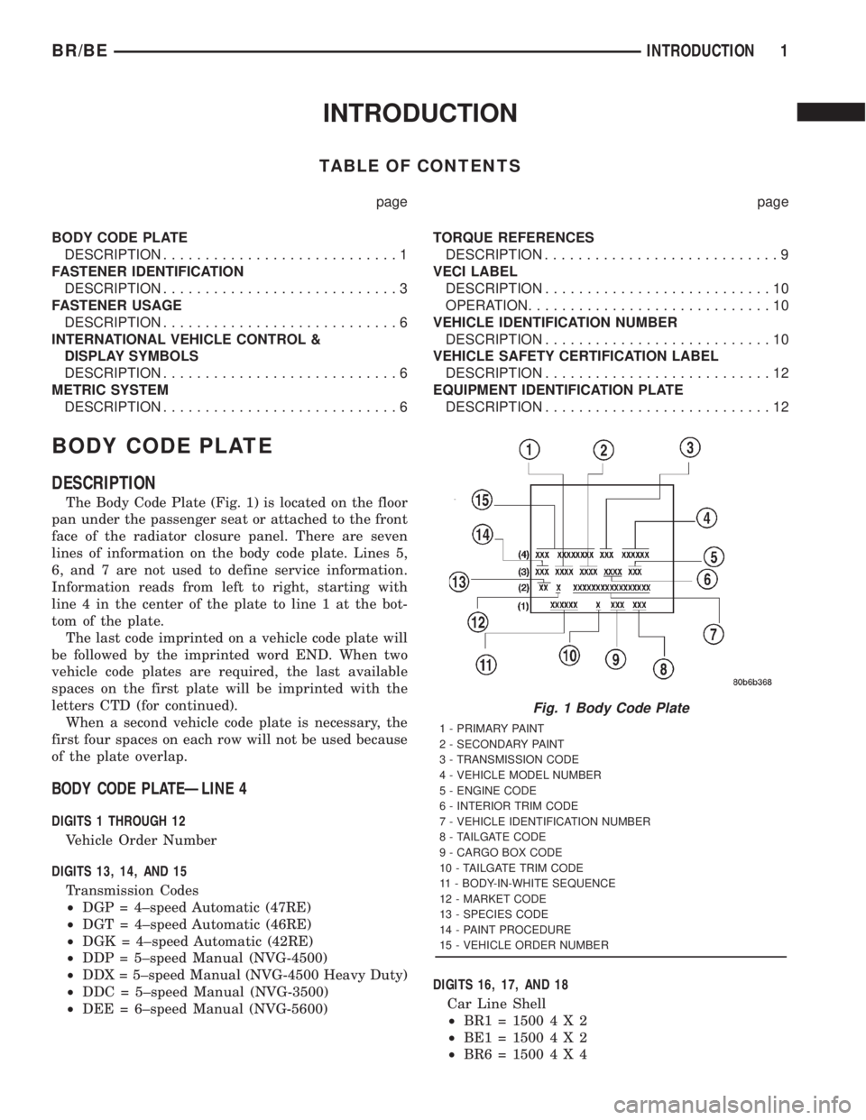
The Body Code Plate (Fig. 1) is located on the floor
pan under the passenger seat or attached to the front
face of the radiator closure panel. There are seven
lines of information on the body code plate. Lines 5,
6, and 7 are not used to define service information.
Information reads from left to right, starting with
line 4 in the center of the plate to line 1 at the bot-
tom of the plate.
The last code imprinted on a vehicle code plate will
be followed by the imprinted word END. When two
vehicle code plates are required, the last available
spaces on the first plate will be imprinted with the
letters CTD (for continued).
When a second vehicle code plate is necessary, the
first four spaces on each row will not be used because
of the plate overlap.
BODY CODE PLATEÐLINE 4
DIGITS 1 THROUGH 12
Vehicle Order Number
DIGITS 13, 14, AND 15
Transmission Codes
²DGP = 4±speed Automatic (47RE)
²DGT = 4±speed Automatic (46RE)
²DGK = 4±speed Automatic (42RE)
²DDP = 5±speed Manual (NVG-4500)
²DDX = 5±speed Manual (NVG-4500 Heavy Duty)
²DDC = 5±speed Manual (NVG-3500)
²DEE = 6±speed Manual (NVG-5600)DIGITS 16, 17, AND 18
Car Line Shell
²BR1=15004X2
²BE1=15004X2
²BR6=15004X4
Fig. 1 Body Code Plate
1 - PRIMARY PAINT
2 - SECONDARY PAINT
3 - TRANSMISSION CODE
4 - VEHICLE MODEL NUMBER
5 - ENGINE CODE
6 - INTERIOR TRIM CODE
7 - VEHICLE IDENTIFICATION NUMBER
8 - TAILGATE CODE
9 - CARGO BOX CODE
10 - TAILGATE TRIM CODE
11 - BODY-IN-WHITE SEQUENCE
12 - MARKET CODE
13 - SPECIES CODE
14 - PAINT PROCEDURE
15 - VEHICLE ORDER NUMBER
BR/BEINTRODUCTION 1
Page 3 of 2889
²BE6=15004X4
²BR2=25004X2
²BE2=25004X2
²BR7=25004X4
²BE7=25004X4
²BR3=35004X2
²BE3=35004X2
²BR8=35004X4
²BE8=35004X4
DIGIT 19
Price Class
²L = Ram Truck (All)
DIGITS 20 AND 21
Body Type
²
31 = Ram Truck Club Cab (138.7 in. Wheel Base)
²32 = Ram Truck Club Cab (154.7 in. Wheel Base)
²33 = Ram Truck Quad Cab (138.7 in. Wheel Base)
²34 = Ram Truck Quad Cab (154.7 in. Wheel Base)
²61 = Ram Truck (118.7 in. Wheel Base)
²62 = Ram Truck (134.7 in. Wheel Base)
²63 = Ram Truck Cab Chassis (138.7 in. Wheel
Base)
²
64 = Ram Truck Cab Chassis (162.7 in. Wheel
Base)
BODY CODE PLATEÐLINE 3
DIGITS 1,2, AND 3
Paint Procedure
²APA = Monotone
²AP9 = Special
²APB = Two-tone (Waterfall)
²APC = Two-tone (Centerband)
²APD = Two-tone (Lower break)
DIGIT 4
Open Space
DIGITS 5 THROUGH 8
Primary Paint
Refer to Group 23, Body for color codes.
DIGIT 9
Open Space
DIGITS 10 THROUGH 13
Secondary Paint
DIGIT 14
Open Space
DIGITS 15 THROUGH 18
Interior Trim CodeDIGIT 19
Open Space
DIGITS 20, 21, AND 22
Engine Code
²EHC = 3.9 L 6 cyl. MPI Gasoline
²ELF = 5.2 L 8 cyl. MPI Gasoline
²ELN = 5.2 L 8 cyl. (CNG)
²EML = 5.9 L 8 cyl. MPI Gasoline
²EMM = 5.9 L 8 cyl. MPI Gasoline (Heavy Duty)
²ETC = 5.9 L 6 cyl. Turbo Diesel
²EWA = 8.0 L 10 cyl. MPI Gasoline
BODY CODE PLATEÐLINE 2
DIGIT 1 Open Space
DIGITS 2 AND 3 Species Code. (Used for Manufacturing)
DIGIT 4
Open Space
DIGIT 5
Market Code
²B = International
²C = Canada
²M = Mexico
²U = United States
DIGIT 6
Open Space
DIGITS 7 THROUGH 23
Vehicle Identification Number (VIN)
Refer to Vehicle Identification Number (VIN) para-
graph for proper breakdown of VIN code.
BODY CODE PLATEÐLINE 1
DIGITS 1 THROUGH 6 Body-in-white assembly sequence.
DIGIT 7
Open Space
DIGIT 8 Tailgate trim code.
DIGIT 9
Open Space
DIGITS 10 THROUGH 12 Cargo box code
²XBS = Sweptline
DIGIT 13
Open Space
2 INTRODUCTIONBR/BE
BODY CODE PLATE (Continued)
Page 4 of 2889
DIGITS 14 THROUGH 16 Tailgate code
²MWD = Plain Tailgate
²MPB = Tailgate Applique (Black)
FASTENER IDENTIFICATION
DESCRIPTION
The SAE bolt strength grades range from grade 2
to grade 8. The higher the grade number, the greater
the bolt strength. Identification is determined by theline marks on the top of each bolt head. The actual
bolt strength grade corresponds to the number of line
marks plus 2. The most commonly used metric bolt
strength classes are 9.8 and 10.9. The metric
strength class identification number is imprinted on
the head of the bolt. The higher the class number,
the greater the bolt strength. Some metric nuts are
imprinted with a single-digit strength class on the
nut face. Refer to the Fastener Identification and
Fastener Strength Charts.
BR/BEINTRODUCTION 3
BODY CODE PLATE (Continued)
Page 599 of 2889
MARKER LAMP
REMOVAL..............................22
INSTALLATION...........................23
MULTI-FUNCTION SWITCH
DESCRIPTION...........................23
OPERATION.............................24
DIAGNOSIS AND TESTING.................25
MULTI-FUNCTION SWITCH...............25
REMOVAL..............................27
INSTALLATION...........................28
OUTBOARD IDENTIFICATION LAMP
REMOVAL..............................28
INSTALLATION...........................29
PARK/TURN SIGNAL LAMP
REMOVAL..............................29
INSTALLATION...........................29
PARK/TURN SIGNAL LAMP UNIT
REMOVAL..............................29INSTALLATION...........................29
TAIL LAMP
DESCRIPTION...........................29
OPERATION.............................29
REMOVAL..............................29
INSTALLATION...........................30
TAIL LAMP UNIT
REMOVAL..............................30
INSTALLATION...........................30
TURN SIGNAL CANCEL CAM
DESCRIPTION...........................30
OPERATION.............................31
UNDERHOOD LAMP
REMOVAL..............................31
INSTALLATION...........................32
UNDERHOOD LAMP UNIT
REMOVAL..............................32
INSTALLATION...........................32
LAMPS/LIGHTING - EXTERIOR
DESCRIPTION - TURN SIGNAL & HAZARD
WARNING SYSTEM
A turn signal and hazard warning system is stan-
dard factory-installed safety equipment on this
model. The turn signal and hazard warning system
includes the following major components, which are
described in further detail elsewhere in this service
information:
²Combination Flasher- The electronic combi-
nation flasher is installed in the Junction Block (JB),
which is located behind the fuse access panel on the
left outboard end of the instrument panel.
²Hazard Warning Switch- The hazard warning
switch is integral to the multi-function switch on the
left side of the steering column. The hazard warning
switch button protrudes from a dedicated opening in
the shroud on the top of the steering column, just
below the steering wheel.
²Turn Signal Cancel Cam- The turn signal
cancel cam is integral to the clockspring, which is
located beneath the steering column shrouds at the
top of the steering column, just below the steering
wheel.
²Turn Signal Indicators- The two turn signal
indicators, one right and one left, are integral to the
ElectroMechanical Instrument Cluster (EMIC)
located in the instrument panel.
²Turn Signal Lamps- The front turn signal
lamps are integral to the lower front outboard ends
of the headlamp modules, located just outboard of the
two sides of the radiator grille opening. The rear
turn signal lamps are integral to the taillamp mod-
ules located on either side of the vehicle. For pickup
models the taillamp modules are secured to the rear
of the quarter panels at each side of the tailgate
opening. For cab and chassis models the taillampmodules are secured by a stamped steel bracket on
the outboard side of each frame rail near the rear of
the vehicle.
²Turn Signal Switch- The turn signal switch is
integral to the multi-function switch on the left side
of the steering column. The multi-function switch
control stalk that actuates the turn signal switch
protrudes from a dedicated opening in the steering
column shrouds on the left side of the column, just
below the steering wheel.
Hard wired circuitry connects the turn signal and
hazard warning system components to each other
through the electrical system of the vehicle. These
hard wired circuits are integral to several wire har-
nesses, which are routed throughout the vehicle and
retained by many different methods. These circuits
may be connected to each other, to the vehicle elec-
trical system and to the turn signal and hazard
warning system components through the use of a
combination of soldered splices, splice block connec-
tors and many different types of wire harness termi-
nal connectors and insulators. Refer to the
appropriate wiring information. The wiring informa-
tion includes wiring diagrams, proper wire and con-
nector repair procedures, details of wire harness
routing and retention, connector pin-out information
and location views for the various wire harness con-
nectors, splices and grounds.
OPERATION - TURN SIGNAL & HAZARD
WARNING SYSTEM
The turn signal system operates on battery current
received on a fused ignition switch output (run-acc)
circuit so that the turn signals will only operate with
the ignition switch in the On or Accessory positions.
The hazard warning system operates on non-
switched battery current received on a fused B(+) cir-
cuit so that the hazard warning remains operational
8L - 2 LAMPS/LIGHTING - EXTERIORBR/BE
Page 620 of 2889
(1) Disconnect and isolate the battery negative
cable.
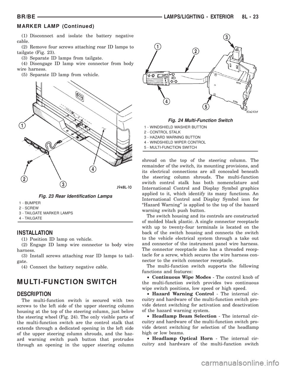
(2) Remove four screws attaching rear ID lamps to
tailgate (Fig. 23).
(3) Separate ID lamps from tailgate.
(4) Disengage ID lamp wire connector from body
wire harness.
(5) Separate ID lamp from vehicle.
INSTALLATION
(1) Position ID lamp on vehicle.
(2) Engage ID lamp wire connector to body wire
harness.
(3) Install screws attaching rear ID lamps to tail-
gate.
(4) Connect the battery negative cable.
MULTI-FUNCTION SWITCH
DESCRIPTION
The multi-function switch is secured with two
screws to the left side of the upper steering column
housing at the top of the steering column, just below
the steering wheel (Fig. 24). The only visible parts of
the multi-function switch are the control stalk that
extends through a dedicated opening in the left side
of the upper steering column shrouds, and the haz-
ard warning switch push button that protrudes
through an opening in the upper steering columnshroud on the top of the steering column. The
remainder of the switch, its mounting provisions, and
its electrical connections are all concealed beneath
the steering column shrouds. The multi-function
switch control stalk has both nomenclature and
International Control and Display Symbol graphics
applied to it, which identify its many functions. An
International Control and Display Symbol icon for
ªHazard Warningº is applied to the top of the hazard
warning switch push button.
The switch housing and its controls are constructed
of molded black plastic. A single connector receptacle
with up to twenty-four terminals is located on the
back of the switch housing and connects the switch
to the vehicle electrical system through a take out
and connector of the instrument panel wire harness.
The connector receptacle also has a threaded recep-
tacle for a screw, which secures the wire harness con-
nector to the switch connector receptacle.
The multi-function switch supports the following
functions and features:
²Continuous Wipe Modes- The control knob of
the multi-function switch provides two continuous
wipe switch positions, low speed or high speed.
²Hazard Warning Control- The internal cir-
cuitry and hardware of the multi-function switch pro-
vide detent switching for activation and deactivation
of the hazard warning system.
²Headlamp Beam Selection- The internal cir-
cuitry and hardware of the multi-function switch pro-
vide detent switching for selection of the headlamp
high or low beams.
²Headlamp Optical Horn- The internal cir-
cuitry and hardware of the multi-function switch
Fig. 23 Rear Identification Lamps
1 - BUMPER
2 - SCREW
3 - TAILGATE MARKER LAMPS
4 - TAILGATE
Fig. 24 Multi-Function Switch
1 - WINDSHIELD WASHER BUTTON
2 - CONTROL STALK
3 - HAZARD WARNING BUTTON
4 - WINDSHIELD WIPER CONTROL
5 - MULTI-FUNCTION SWITCH
BR/BELAMPS/LIGHTING - EXTERIOR 8L - 23
MARKER LAMP (Continued)
Page 757 of 2889
Component Page
Map Lamps.......................... 8W-49
Outboard Clearance Lamp............... 8W-50
Outboard Headlamp................... 8W-50
Outboard Identification Lamp............ 8W-50
Output Speed Sensor................... 8W-31
Overdrive Switch...................... 8W-31
Overhead Console..................... 8W-49
Oxygen Sensors....................... 8W-30
Park Brake Switch.................. 8W-40, 50
Park/Neutral Position Switch.......... 8W-30, 51
Park/Turn Signal Lamp................. 8W-52
Passenger Airbag On/Off Switch.......... 8W-43
Passenger Airbag...................... 8W-43
Power Distribution Center............... 8W-10
Power Mirror Switch................... 8W-62
Power Mirror......................... 8W-62
Power Outlet......................... 8W-41
Power Seat Front Vertical Motors......... 8W-63
Power Seat Horizontal Motors............ 8W-63
Power Seat Rear Vertical Motor........... 8W-63
Power Seat Switch..................... 8W-63
Power Window Motors.................. 8W-60
Powertrain Control Module.............. 8W-30
PTO Switch.......................... 8W-30
Quad High Beam Relay................. 8W-50
Radio Choke Relay..................... 8W-47Component Page
Radio............................... 8W-47
Remote Radio Switch................... 8W-47
Seat Belt Switch...................... 8W-40
Seat Heat Interface Module.............. 8W-63
Security Relay........................ 8W-39
Speakers............................ 8W-47
Speed Control Servo................... 8W-33
Speed Control Switch................... 8W-33
Splice Information..................... 8W-70
Tail/Stop/Turn Signal Lamp.............. 8W-51
Tailgate Lamp........................ 8W-51
Throttle Position Sensor................ 8W-30
Trailer Tow Connector.................. 8W-54
Trailer Tow Relay...................... 8W-54
Transmission Control Relay.............. 8W-31
Transmission Solenoid Assembly.......... 8W-31
Turn Signal/Hazard Switch.............. 8W-52
Underhood Lamp...................... 8W-44
Visor/Vanity Lamp..................... 8W-44
Washer Fluid Level Switch.............. 8W-40
Water In Fuel Sensor................... 8W-30
Wheel Speed Sensors................ 8W-34, 35
Windshield Washer Pump............... 8W-53
Wiper Motor Relay..................... 8W-53
Wiper Motor.......................... 8W-53
BR/BE8W-02 COMPONENT INDEX 8W - 02 - 1
Page 808 of 2889
8W-15 GROUND DISTRIBUTION
Component Page
A/C Compressor Clutch............... 8W-15-10, 8
A/C-Heater Control.................... 8W-15-14
A/C Heater Temperature Select........... 8W-15-12
Aftermarket Trailer Tow Connector......... 8W-15-6
Airbag Control Module.................. 8W-15-5
Ash Receiver Lamp.................... 8W-15-14
Automatic Day/Night Mirror............. 8W-15-13
Auxiliary Battery..................... 8W-15-11
Battery............................ 8W-15-11
Blend Door Actuator................... 8W-15-12
Blower Motor Relay.................... 8W-15-2
Brake Lamp Switch................... 8W-15-12
Brake Pressure Switch.................. 8W-15-3
Center High Mounted Stop Lamp No. 1..... 8W-15-17
Center High Mounted Stop Lamp No. 2..... 8W-15-17
Center Identification Lamp.............. 8W-15-18
Central Timer Module C1............... 8W-15-12
Central Timer Module C2............... 8W-15-13
Cigar Lighter........................ 8W-15-14
Clockspring.......................... 8W-15-4
Combination Flasher.................. 8W-15-13
Controller Antilock Brake................ 8W-15-5
Cummins Bus....................... 8W-15-10
Cup Holder Lamp..................... 8W-15-14
Data Link Connector.............. 8W-15-8, 10, 12
Daytime Running Lamp Module......... 8W-15-2, 3
Driver Cylinder Lock Switch............. 8W-15-16
Driver Door Ajar Switch................ 8W-15-16
Driver Door Window/Lock Switch....... 8W-15-16, 17
Driver Heated Seat Cushion............. 8W-15-15
Driver Heated Seat Switch.............. 8W-15-13
Driver Power Seat Switch............ 8W-15-15, 17
Electric Brake Provision................ 8W-15-14
Engine Control Module.................. 8W-15-9
Engine Starter Motor Relay............. 8W-15-8, 9
Fuel Heater Relay..................... 8W-15-2
Fuel Heater......................... 8W-15-10
Fuel Injection Pump.................... 8W-15-9
Fuel Pump Module..................... 8W-15-7
Fuel Pump Relay...................... 8W-15-2
Fuel Transfer Pump................... 8W-15-10
G100.......................... 8W-15-12, 5, 7
G101............................... 8W-15-5
G102............................... 8W-15-2
G105............................... 8W-15-8
G107.............................. 8W-15-10
G113 .............................. 8W-15-11
G114 .............................. 8W-15-11
G115 .............................. 8W-15-11
G116 .............................. 8W-15-11
G117 .............................. 8W-15-11
G118 .............................. 8W-15-11
G120.............................. 8W-15-11
G200......................... 8W-15-7, 12, 14
G201........................... 8W-15-12, 14
G300.............................. 8W-15-16
G301.............................. 8W-15-17
G302.............................. 8W-15-18
Glove Box Lamp And Switch............. 8W-15-14
Headlamp Beam Select Switch............ 8W-15-14
Headlamp Switch.................. 8W-15-13, 14
Heated Mirror Switch.................. 8W-15-13
High Note Horn....................... 8W-15-7
Ignition Switch....................... 8W-15-13
Instrument Cluster................. 8W-15-12, 14
Intake Air Heater Relay No. 1............. 8W-15-9Component Page
Intake Air Heater Relay No. 2............. 8W-15-9
Joint Connector No. 1................... 8W-15-2
Joint Connector No. 2................... 8W-15-9
Joint Connector No. 3................... 8W-15-7
Joint Connector No. 4................... 8W-15-3
Joint Connector No. 5.................. 8W-15-13
Joint Connector No. 6................... 8W-15-4
Joint Connector No. 8................ 8W-15-13, 5
Junction Block.................... 8W-15-12, 13
Left Back-Up Lamp.................... 8W-15-6
Left Front Door Speaker................. 8W-15-4
Left Front Fender Lamp................. 8W-15-6
Left License Lamp..................... 8W-15-6
Left Outboard Clearance Lamp........... 8W-15-18
Left Outboard Identification Lamp......... 8W-15-18
Left Park/Turn Signal Lamp.............. 8W-15-3
Left Power Mirror..................... 8W-15-16
Left Rear Fender Lamp................. 8W-15-6
Left Remote Radio Switch................ 8W-15-4
Left Tail/Stop/Turn Signal Lamp........... 8W-15-6
Left Visor/Vanity Lamp................. 8W-15-13
Low Note Horn....................... 8W-15-7
Overdrive Switch..................... 8W-15-12
Overhead Console..................... 8W-15-12
Oxygen Sensor 1/2 Left Bank Down......... 8W-15-8
Oxygen Sensor 1/2 Pre-Catalyst............ 8W-15-8
Oxygen Sensor 1/3 Post-Catalyst........... 8W-15-8
Oxygen Sensor 2/2 Right Bank Down........ 8W-15-8
Passenger Airbag On/Off Switch........... 8W-15-5
Passenger Cylinder Lock Switch.......... 8W-15-16
Passenger Door Ajar Switch.............. 8W-15-16
Passenger Door Window/Lock Switch....... 8W-15-16
Passenger Heated Seat Cushion........... 8W-15-15
Passenger Heated Seat Switch............ 8W-15-13
Passenger Power Seat Switch............ 8W-15-15
Power Distribution Center............... 8W-15-2
Power Mirror Switch................... 8W-15-16
Power Outlet........................ 8W-15-14
Powertrain Control Module............ 8W-15-8 , 10
Quad High Beam Relay................. 8W-15-2
Radio Choke Relay..................... 8W-15-4
Radio.............................. 8W-15-5
Right Back-Up Lamp................... 8W-15-6
Right Front Door Speaker................ 8W-15-4
Right Front Fender Lamp................ 8W-15-6
Right License Lamp.................... 8W-15-6
Right Outboard Clearance Lamp.......... 8W-15-18
Right Outboard Identification Lamp........ 8W-15-18
Right Park/Turn Signal Lamp............. 8W-15-7
Right Power Mirror................... 8W-15-16
Right Rear Fender Lamp................ 8W-15-6
Right Remote Radio Switch............... 8W-15-4
Right Tail/Stop/Turn Signal Lamp.......... 8W-15-6
Right Visor/Vanity Lamp................ 8W-15-13
Seat Belt Switch................... 8W-15-15, 17
Seat Heat Interface Module.............. 8W-15-15
Security Relay........................ 8W-15-2
Speed Control Servo.................... 8W-15-3
Tailgate Lamp........................ 8W-15-6
Trailer Tow Connector.................. 8W-15-6
Trailer Tow Relay...................... 8W-15-2
Underhood Lamp...................... 8W-15-3
Washer Fluid Level Switch............... 8W-15-3
Windshield Washer Pump................ 8W-15-7
Wiper Motor......................... 8W-15-7
BR/BE8W-15 GROUND DISTRIBUTION 8W - 15 - 1
Page 970 of 2889
8W-51 REAR LIGHTING
Component Page
Aftermarket Center High Mounted
Stop Lamp....................... 8W-51-4
Aftermarket Trailer Tow Connector...... 8W-51-2
Automatic Day/Night Mirror............ 8W-51-2
Back-Up Lamp Switch................ 8W-51-2
Brake Lamp Switch.................. 8W-51-3
Center High Mounted Stop Lamp No. 1 . . . 8W-51-4
Center High Mounted Stop Lamp No. 2 . . . 8W-51-4
Electric Brake Provision............... 8W-51-4
Fuse 7 (JB)......................... 8W-51-2
Fuse 5 (PDC)....................... 8W-51-3
Fuse F (PDC)....................... 8W-51-4
G100.......................... 8W-51-2, 5, 6
G200.............................. 8W-51-3
Headlamp Switch.................... 8W-51-4
Joint Connector No. 1............... 8W-51-2, 3
Joint Connector No. 6................. 8W-51-3
Junction Block...................... 8W-51-2Component Page
Left Back-Up Lamp.................. 8W-51-2
Left Front Fender Lamp............... 8W-51-6
Left License Lamp................. 8W-51-5, 6
Left Rear Fender Lamp............... 8W-51-6
Left Tail/Stop/Turn Signal Lamp......... 8W-51-5
Park/Neutral Position Switch........... 8W-51-2
Power Distribution Center........... 8W-51-3, 4
Powertrain Control Module............. 8W-51-3
Right Back-Up Lamp................. 8W-51-2
Right Front Fender Lamp.............. 8W-51-6
Right License Lamp.................. 8W-51-5
Right Rear Fender Lamp.............. 8W-51-6
Right Tail/Stop/Turn Signal Lamp....... 8W-51-5
Speed Control Servo.................. 8W-51-3
Tailgate Lamp....................... 8W-51-6
Trailer Tow Connector................. 8W-51-2
Turn Signal/Hazard Switch............. 8W-51-5
BR/BE8W-51 REAR LIGHTING 8W - 51 - 1
Page 1016 of 2889
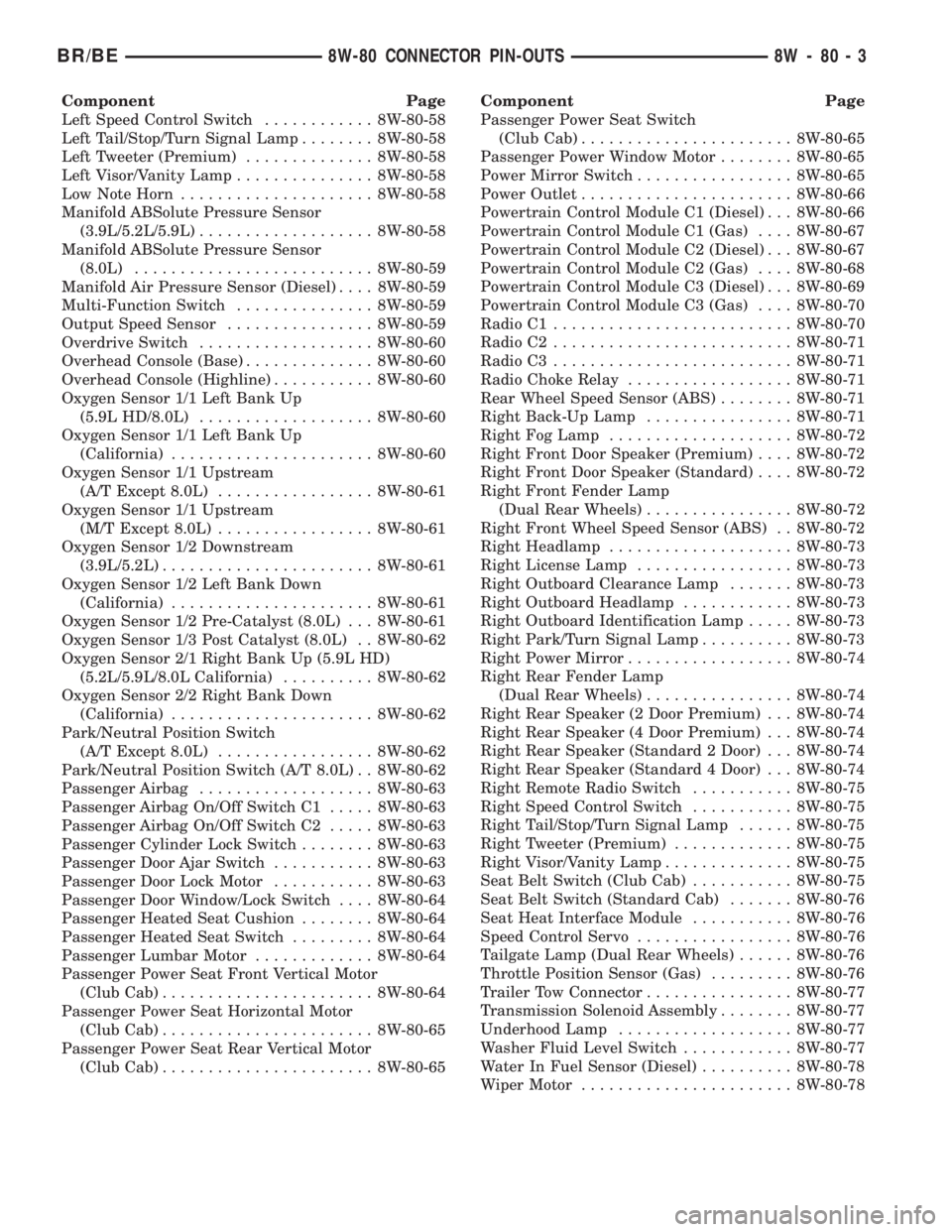
Component Page
Left Speed Control Switch............ 8W-80-58
Left Tail/Stop/Turn Signal Lamp........ 8W-80-58
Left Tweeter (Premium).............. 8W-80-58
Left Visor/Vanity Lamp............... 8W-80-58
Low Note Horn..................... 8W-80-58
Manifold ABSolute Pressure Sensor
(3.9L/5.2L/5.9L)................... 8W-80-58
Manifold ABSolute Pressure Sensor
(8.0L).......................... 8W-80-59
Manifold Air Pressure Sensor (Diesel).... 8W-80-59
Multi-Function Switch............... 8W-80-59
Output Speed Sensor................ 8W-80-59
Overdrive Switch................... 8W-80-60
Overhead Console (Base).............. 8W-80-60
Overhead Console (Highline)........... 8W-80-60
Oxygen Sensor 1/1 Left Bank Up
(5.9L HD/8.0L)................... 8W-80-60
Oxygen Sensor 1/1 Left Bank Up
(California)...................... 8W-80-60
Oxygen Sensor 1/1 Upstream
(A/T Except 8.0L)................. 8W-80-61
Oxygen Sensor 1/1 Upstream
(M/T Except 8.0L)................. 8W-80-61
Oxygen Sensor 1/2 Downstream
(3.9L/5.2L)....................... 8W-80-61
Oxygen Sensor 1/2 Left Bank Down
(California)...................... 8W-80-61
Oxygen Sensor 1/2 Pre-Catalyst (8.0L) . . . 8W-80-61
Oxygen Sensor 1/3 Post Catalyst (8.0L) . . 8W-80-62
Oxygen Sensor 2/1 Right Bank Up (5.9L HD)
(5.2L/5.9L/8.0L California).......... 8W-80-62
Oxygen Sensor 2/2 Right Bank Down
(California)...................... 8W-80-62
Park/Neutral Position Switch
(A/T Except 8.0L)................. 8W-80-62
Park/Neutral Position Switch (A/T 8.0L) . . 8W-80-62
Passenger Airbag................... 8W-80-63
Passenger Airbag On/Off Switch C1..... 8W-80-63
Passenger Airbag On/Off Switch C2..... 8W-80-63
Passenger Cylinder Lock Switch........ 8W-80-63
Passenger Door Ajar Switch........... 8W-80-63
Passenger Door Lock Motor........... 8W-80-63
Passenger Door Window/Lock Switch.... 8W-80-64
Passenger Heated Seat Cushion........ 8W-80-64
Passenger Heated Seat Switch......... 8W-80-64
Passenger Lumbar Motor............. 8W-80-64
Passenger Power Seat Front Vertical Motor
(Club Cab)....................... 8W-80-64
Passenger Power Seat Horizontal Motor
(Club Cab)....................... 8W-80-65
Passenger Power Seat Rear Vertical Motor
(Club Cab)....................... 8W-80-65Component Page
Passenger Power Seat Switch
(Club Cab)....................... 8W-80-65
Passenger Power Window Motor........ 8W-80-65
Power Mirror Switch................. 8W-80-65
Power Outlet....................... 8W-80-66
Powertrain Control Module C1 (Diesel) . . . 8W-80-66
Powertrain Control Module C1 (Gas).... 8W-80-67
Powertrain Control Module C2 (Diesel) . . . 8W-80-67
Powertrain Control Module C2 (Gas).... 8W-80-68
Powertrain Control Module C3 (Diesel) . . . 8W-80-69
Powertrain Control Module C3 (Gas).... 8W-80-70
Radio C1.......................... 8W-80-70
Radio C2.......................... 8W-80-71
Radio C3.......................... 8W-80-71
Radio Choke Relay.................. 8W-80-71
Rear Wheel Speed Sensor (ABS)........ 8W-80-71
Right Back-Up Lamp................ 8W-80-71
Right Fog Lamp.................... 8W-80-72
Right Front Door Speaker (Premium).... 8W-80-72
Right Front Door Speaker (Standard).... 8W-80-72
Right Front Fender Lamp
(Dual Rear Wheels)................ 8W-80-72
Right Front Wheel Speed Sensor (ABS) . . 8W-80-72
Right Headlamp.................... 8W-80-73
Right License Lamp................. 8W-80-73
Right Outboard Clearance Lamp....... 8W-80-73
Right Outboard Headlamp............ 8W-80-73
Right Outboard Identification Lamp..... 8W-80-73
Right Park/Turn Signal Lamp.......... 8W-80-73
Right Power Mirror.................. 8W-80-74
Right Rear Fender Lamp
(Dual Rear Wheels)................ 8W-80-74
Right Rear Speaker (2 Door Premium) . . . 8W-80-74
Right Rear Speaker (4 Door Premium) . . . 8W-80-74
Right Rear Speaker (Standard 2 Door) . . . 8W-80-74
Right Rear Speaker (Standard 4 Door) . . . 8W-80-74
Right Remote Radio Switch........... 8W-80-75
Right Speed Control Switch........... 8W-80-75
Right Tail/Stop/Turn Signal Lamp...... 8W-80-75
Right Tweeter (Premium)............. 8W-80-75
Right Visor/Vanity Lamp.............. 8W-80-75
Seat Belt Switch (Club Cab)........... 8W-80-75
Seat Belt Switch (Standard Cab)....... 8W-80-76
Seat Heat Interface Module........... 8W-80-76
Speed Control Servo................. 8W-80-76
Tailgate Lamp (Dual Rear Wheels)...... 8W-80-76
Throttle Position Sensor (Gas)......... 8W-80-76
Trailer Tow Connector................ 8W-80-77
Transmission Solenoid Assembly........ 8W-80-77
Underhood Lamp................... 8W-80-77
Washer Fluid Level Switch............ 8W-80-77
Water In Fuel Sensor (Diesel).......... 8W-80-78
Wiper Motor....................... 8W-80-78
BR/BE8W-80 CONNECTOR PIN-OUTS 8W - 80 - 3
Page 1089 of 2889
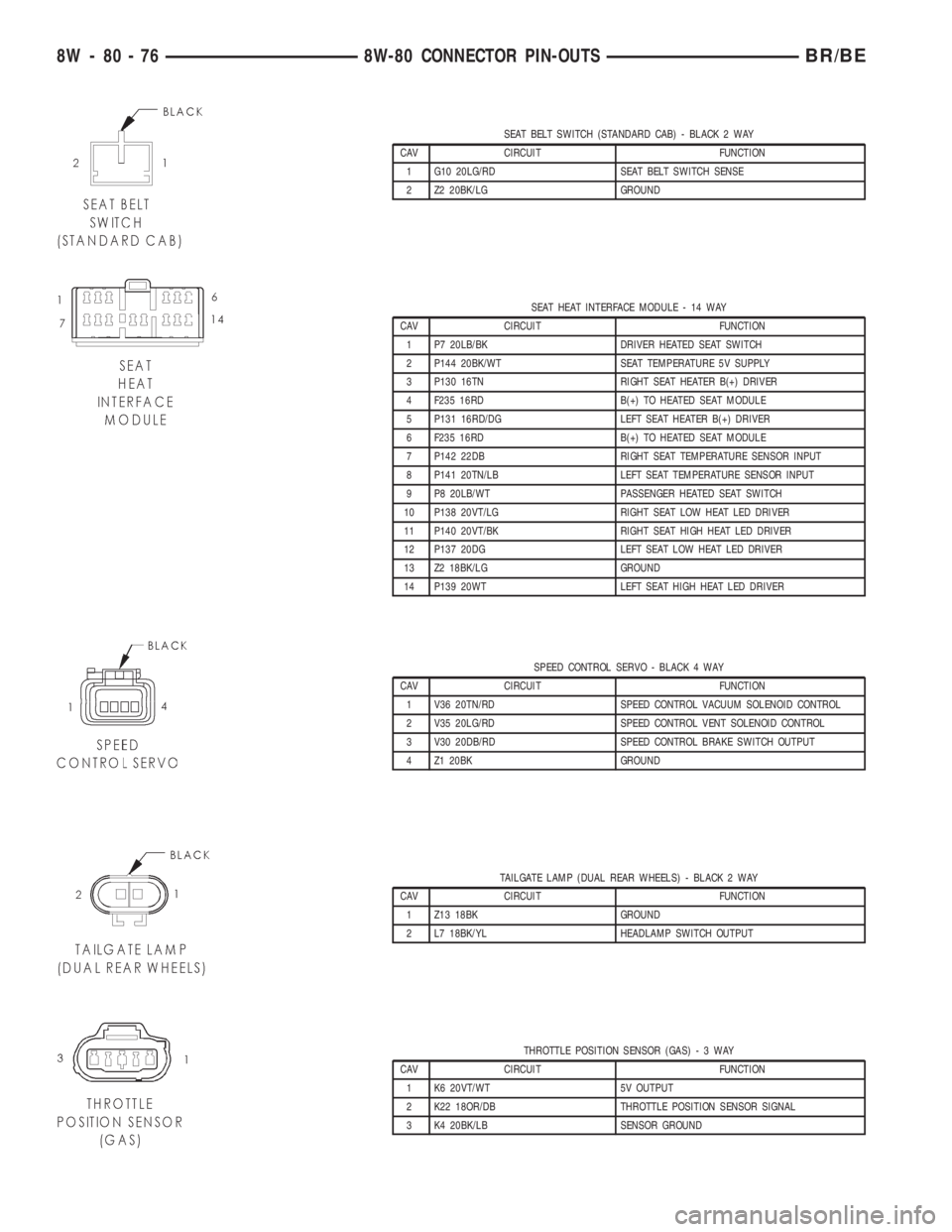
SEAT BELT SWITCH (STANDARD CAB) - BLACK 2 WAY
CAV CIRCUIT FUNCTION
1 G10 20LG/RD SEAT BELT SWITCH SENSE
2 Z2 20BK/LG GROUND
SEAT HEAT INTERFACE MODULE - 14 WAY
CAV CIRCUIT FUNCTION
1 P7 20LB/BK DRIVER HEATED SEAT SWITCH
2 P144 20BK/WT SEAT TEMPERATURE 5V SUPPLY
3 P130 16TN RIGHT SEAT HEATER B(+) DRIVER
4 F235 16RD B(+) TO HEATED SEAT MODULE
5 P131 16RD/DG LEFT SEAT HEATER B(+) DRIVER
6 F235 16RD B(+) TO HEATED SEAT MODULE
7 P142 22DB RIGHT SEAT TEMPERATURE SENSOR INPUT
8 P141 20TN/LB LEFT SEAT TEMPERATURE SENSOR INPUT
9 P8 20LB/WT PASSENGER HEATED SEAT SWITCH
10 P138 20VT/LG RIGHT SEAT LOW HEAT LED DRIVER
11 P140 20VT/BK RIGHT SEAT HIGH HEAT LED DRIVER
12 P137 20DG LEFT SEAT LOW HEAT LED DRIVER
13 Z2 18BK/LG GROUND
14 P139 20WT LEFT SEAT HIGH HEAT LED DRIVER
SPEED CONTROL SERVO - BLACK 4 WAY
CAV CIRCUIT FUNCTION
1 V36 20TN/RD SPEED CONTROL VACUUM SOLENOID CONTROL
2 V35 20LG/RD SPEED CONTROL VENT SOLENOID CONTROL
3 V30 20DB/RD SPEED CONTROL BRAKE SWITCH OUTPUT
4 Z1 20BK GROUND
TAILGATE LAMP (DUAL REAR WHEELS) - BLACK 2 WAY
CAV CIRCUIT FUNCTION
1 Z13 18BK GROUND
2 L7 18BK/YL HEADLAMP SWITCH OUTPUT
THROTTLE POSITION SENSOR (GAS)-3WAY
CAV CIRCUIT FUNCTION
1 K6 20VT/WT 5V OUTPUT
2 K22 18OR/DB THROTTLE POSITION SENSOR SIGNAL
3 K4 20BK/LB SENSOR GROUND
8W - 80 - 76 8W-80 CONNECTOR PIN-OUTSBR/BE