steering column ignition switch DODGE RAM 2001 Service User Guide
[x] Cancel search | Manufacturer: DODGE, Model Year: 2001, Model line: RAM, Model: DODGE RAM 2001Pages: 2889, PDF Size: 68.07 MB
Page 523 of 2889
The indicator lamps in the heated seat switches
receive battery current through a fused ignition
switch output (run) circuit when the ignition switch
is in the On position. The ground side of each indi-
cator lamp is controlled by a separate (high or low/
driver or passenger) indicator lamp driver circuit by
the heated seat module. The heated seat module con-
trol of the switch indicator lamps also allows the
module to provide diagnostic feedback to the vehicle
operator to indicate monitored heated seat system
faults by flashing the indicator lamps on and off. One
side of the incandescent back lighting bulb in each
heated seat switch is connected to ground at all
times. The other side of the incandescent bulb is con-
nected to the fused panel lamps dimmer switch sig-
nal circuit. These bulbs are energized when the park
lamps or headlamps are turned on, and their illumi-
nation intensity is controlled by the panel lamps dim-
mer switch.
DIAGNOSIS & TESTING - HEATED SEAT
SWITCH
Refer toWiring Diagramsfor the location of com-
plete heated seat system wiring diagrams.
WARNING: ON VEHICLES EQUIPPED WITH AIR-
BAGS, DISABLE THE AIRBAG SYSTEM BEFORE
ATTEMPTING ANY STEERING WHEEL, STEERING
COLUMN, OR INSTRUMENT PANEL COMPONENT
DIAGNOSIS OR SERVICE. DISCONNECT AND ISO-
LATE THE BATTERY NEGATIVE (GROUND) CABLE,
THEN WAIT TWO MINUTES FOR THE AIRBAG SYS-
TEM CAPACITOR TO DISCHARGE BEFORE PER-
FORMING FURTHER DIAGNOSIS OR SERVICE. THIS
IS THE ONLY SURE WAY TO DISABLE THE AIRBAG
SYSTEM. FAILURE TO TAKE THE PROPER PRE-
CAUTIONS COULD RESULT IN ACCIDENTAL AIR-
BAG DEPLOYMENT AND POSSIBLE PERSONAL
INJURY.
(1) If the problem being diagnosed involves inoper-
ative heated seat switch back lighting and the cluster
illumination lamps operate, go to Step 2. If the prob-
lem being diagnosed involves inoperative heated seat
switch back lighting and the cluster illumination
lamps are also inoperative, refer toInstrument
Clusterin the index of this service manual for the
proper cluster illumination lamps diagnosis and test-
ing procedures. If the problem being diagnosed
involves inoperative heated seat switch indicator
lamps and the heated seat elements do not heat,
refer to Step 4. If the problem being diagnosed
involves inoperative heated seat switch indicator
lamps and the heated seat elements do heat, go to
Step 8. If the problem being diagnosed involves a
heated seat switch indicator lamp that remains illu-minated after the heated seat has been turned Off,
refer toHeated Seat Modulein Electronic Control
Modules for the location of the proper heated seat
module diagnosis and testing procedures. Also refer
to the Body Diagnostic Manual for additional diagno-
sis and testing procedures.
(2) Disconnect and isolate the battery negative
cable. Remove the heated seat switch and bezel unit
from the instrument panel. Disconnect the instru-
ment panel wire harness connector from the connec-
tor receptacle on the back of the heated seat switch
to be tested. Check for continuity between the ground
circuit cavity of the instrument panel wire harness
connector for the heated seat switch and a good
ground. There should be continuity. If OK, go to Step
3. If not OK, repair the open ground circuit to ground
as required.
(3) Reconnect the battery negative cable. Turn the
park lamps on with the headlamp switch. Rotate the
panel lamps dimmer thumbwheel on the headlamp
switch upward to just before the interior lamps
detent. Check for battery voltage at the fused panel
lamps dimmer switch signal circuit cavity of the
instrument panel wire harness connector for the
heated seat switch. If OK, replace the faulty heated
seat switch. If not OK, repair the open fused panel
lamps dimmer switch signal circuit to the fuse in the
Junction Block (JB) as required.
(4) Check the fused ignition switch output (run)
fuse in the Junction Block (JB). If OK, go to Step 5.
If not OK, repair the shorted circuit or component as
required and replace the faulty fuse.
(5) Turn the ignition switch to the On position.
Check for battery voltage at the fused ignition switch
output (run) fuse in the JB. If OK, go to Step 6. If
not OK, repair the open fused ignition switch output
(run) circuit to the ignition switch as required.
(6) Disconnect and isolate the battery negative
cable. Remove the heated seat switch and bezel unit
from the instrument panel. Disconnect the instru-
ment panel wire harness connector from the connec-
tor receptacle on the back of the heated seat switch
to be tested. Reconnect the battery negative cable.
Turn the ignition switch to the On position. Check
for battery voltage at the fused ignition switch out-
put (run) circuit cavity of the instrument panel wire
harness connector for the heated seat switch. If OK,
go to Step 7. If not OK, repair the open fused ignition
switch output (run) circuit to the JB fuse as required.
(7) Check the continuity and resistance values of
the heated seat switch in the Neutral, Low and High
positions as shown in the Heated Seat Switch Conti-
nuity chart (Fig. 3). If OK, refer toHeated Seat
Modulein Electronic Control Modules for the loca-
tion of the proper heated seat module diagnosis and
testing procedures. Also refer to the Body Diagnostic
8G - 8 HEATED SEAT SYSTEMBR/BE
DRIVER SEAT HEATER SWITCH (Continued)
Page 529 of 2889
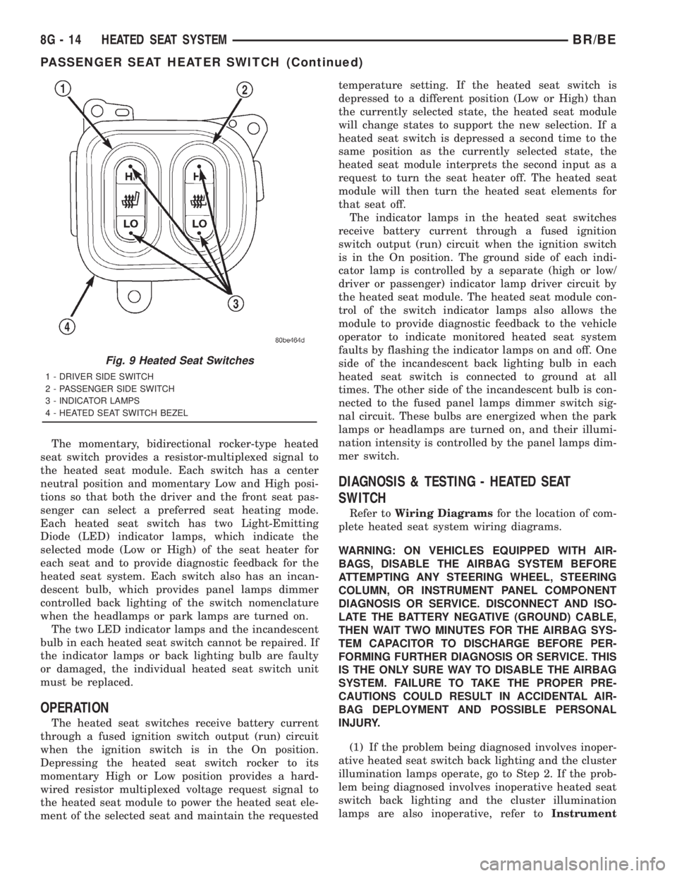
The momentary, bidirectional rocker-type heated
seat switch provides a resistor-multiplexed signal to
the heated seat module. Each switch has a center
neutral position and momentary Low and High posi-
tions so that both the driver and the front seat pas-
senger can select a preferred seat heating mode.
Each heated seat switch has two Light-Emitting
Diode (LED) indicator lamps, which indicate the
selected mode (Low or High) of the seat heater for
each seat and to provide diagnostic feedback for the
heated seat system. Each switch also has an incan-
descent bulb, which provides panel lamps dimmer
controlled back lighting of the switch nomenclature
when the headlamps or park lamps are turned on.
The two LED indicator lamps and the incandescent
bulb in each heated seat switch cannot be repaired. If
the indicator lamps or back lighting bulb are faulty
or damaged, the individual heated seat switch unit
must be replaced.
OPERATION
The heated seat switches receive battery current
through a fused ignition switch output (run) circuit
when the ignition switch is in the On position.
Depressing the heated seat switch rocker to its
momentary High or Low position provides a hard-
wired resistor multiplexed voltage request signal to
the heated seat module to power the heated seat ele-
ment of the selected seat and maintain the requestedtemperature setting. If the heated seat switch is
depressed to a different position (Low or High) than
the currently selected state, the heated seat module
will change states to support the new selection. If a
heated seat switch is depressed a second time to the
same position as the currently selected state, the
heated seat module interprets the second input as a
request to turn the seat heater off. The heated seat
module will then turn the heated seat elements for
that seat off.
The indicator lamps in the heated seat switches
receive battery current through a fused ignition
switch output (run) circuit when the ignition switch
is in the On position. The ground side of each indi-
cator lamp is controlled by a separate (high or low/
driver or passenger) indicator lamp driver circuit by
the heated seat module. The heated seat module con-
trol of the switch indicator lamps also allows the
module to provide diagnostic feedback to the vehicle
operator to indicate monitored heated seat system
faults by flashing the indicator lamps on and off. One
side of the incandescent back lighting bulb in each
heated seat switch is connected to ground at all
times. The other side of the incandescent bulb is con-
nected to the fused panel lamps dimmer switch sig-
nal circuit. These bulbs are energized when the park
lamps or headlamps are turned on, and their illumi-
nation intensity is controlled by the panel lamps dim-
mer switch.
DIAGNOSIS & TESTING - HEATED SEAT
SWITCH
Refer toWiring Diagramsfor the location of com-
plete heated seat system wiring diagrams.
WARNING: ON VEHICLES EQUIPPED WITH AIR-
BAGS, DISABLE THE AIRBAG SYSTEM BEFORE
ATTEMPTING ANY STEERING WHEEL, STEERING
COLUMN, OR INSTRUMENT PANEL COMPONENT
DIAGNOSIS OR SERVICE. DISCONNECT AND ISO-
LATE THE BATTERY NEGATIVE (GROUND) CABLE,
THEN WAIT TWO MINUTES FOR THE AIRBAG SYS-
TEM CAPACITOR TO DISCHARGE BEFORE PER-
FORMING FURTHER DIAGNOSIS OR SERVICE. THIS
IS THE ONLY SURE WAY TO DISABLE THE AIRBAG
SYSTEM. FAILURE TO TAKE THE PROPER PRE-
CAUTIONS COULD RESULT IN ACCIDENTAL AIR-
BAG DEPLOYMENT AND POSSIBLE PERSONAL
INJURY.
(1) If the problem being diagnosed involves inoper-
ative heated seat switch back lighting and the cluster
illumination lamps operate, go to Step 2. If the prob-
lem being diagnosed involves inoperative heated seat
switch back lighting and the cluster illumination
lamps are also inoperative, refer toInstrument
Fig. 9 Heated Seat Switches
1 - DRIVER SIDE SWITCH
2 - PASSENGER SIDE SWITCH
3 - INDICATOR LAMPS
4 - HEATED SEAT SWITCH BEZEL
8G - 14 HEATED SEAT SYSTEMBR/BE
PASSENGER SEAT HEATER SWITCH (Continued)
Page 563 of 2889
The EMIC circuitry operates on battery current
received through a fused B(+) fuse in the Junction
Block (JB) on a non-switched fused B(+) circuit, and
on battery current received through a fused ignition
switch output (st-run) fuse in the JB on a fused igni-
tion switch output (st-run) circuit. This arrangement
allows the EMIC to provide some features regardless
of the ignition switch position, while other features
will operate only with the ignition switch in the Start
or On positions. The EMIC circuitry is grounded
through two separate ground circuits located in one
of the two instrument cluster connectors and take
outs of the instrument panel wire harness. One
ground circuit receives ground through a take out
with an eyelet terminal connector of the instrument
panel wire harness that is secured by a nut to a
ground stud located on the left instrument panel end
bracket, while the other ground circuit receives
ground through a take out with an eyelet terminal
connector of the instrument panel wire harness that
is secured by a nut to a ground stud located on the
back of the instrument panel armature above the
inboard side of the instrument panel steering column
opening.
The EMIC also has a self-diagnostic actuator test
capability, which will test each of the CCD bus mes-
sage-controlled functions of the cluster by lighting
the appropriate indicators and positioning the gauge
needles at several predetermined locations on the
gauge faces in a prescribed sequence. (Refer to 8 -
ELECTRICAL/INSTRUMENT CLUSTER - DIAGNO-
SIS AND TESTING). See the owner's manual in the
vehicle glove box for more information on the fea-
tures, use and operation of the EMIC.
GAUGES
All gauges receive battery current through the
EMIC circuitry when the ignition switch is in the On
or Start positions. With the ignition switch in the Off
position battery current is not supplied to any
gauges, and the EMIC circuitry is programmed to
move all of the gauge needles back to the low end of
their respective scales. Therefore, the gauges do not
accurately indicate any vehicle condition unless the
ignition switch is in the On or Start positions. All of
the EMIC gauges, except the odometer, are air core
magnetic units. Two fixed electromagnetic coils are
located within each gauge. These coils are wrapped
at right angles to each other around a movable per-
manent magnet. The movable magnet is suspended
within the coils on one end of a pivot shaft, while the
gauge needle is attached to the other end of the
shaft. One of the coils has a fixed current flowing
through it to maintain a constant magnetic fieldstrength. Current flow through the second coil
changes, which causes changes in its magnetic field
strength. The current flowing through the second coil
is changed by the EMIC circuitry in response to mes-
sages received over the CCD data bus. The gauge
needle moves as the movable permanent magnet
aligns itself to the changing magnetic fields created
around it by the electromagnets.
The gauges are diagnosed using the EMIC self-di-
agnostic actuator test. (Refer to 8 - ELECTRICAL/
INSTRUMENT CLUSTER - DIAGNOSIS AND
TESTING). Proper testing of the CCD data bus and
the data bus message inputs to the EMIC that con-
trol each gauge require the use of a DRBIIItscan
tool. Refer to the appropriate diagnostic information.
Specific operation details for each gauge may be
found elsewhere in this service manual.
VACUUM-FLUORESCENT DISPLAY
The Vacuum-Fluorescent Display (VFD) module is
soldered to the EMIC circuit board. The display is
active with the ignition switch in the On or Start
positions, and inactive when the ignition switch is in
any other position. The VFD has several display
capabilities including odometer, trip odometer, and
an amber ªCRUISEº indication whenever the
optional speed control system is turned On. The
cruise indicator function of the VFD is automatically
enabled or disabled by the EMIC circuitry based
upon whether the vehicle is equipped with the speed
control option. An odometer/trip odometer switch on
the EMIC circuit board is used to control several of
the display modes. This switch is actuated manually
by depressing the odometer/trip odometer switch
knob that extends through the lower edge of the clus-
ter lens, just right of center. Actuating this switch
momentarily with the ignition switch in the On posi-
tion will toggle the VFD between the odometer and
trip odometer modes. The word ªTRIPº will also
appear in blue-green text when the VFD trip odome-
ter mode is active. Depressing the switch button for
about two seconds while the VFD is in the trip odom-
eter mode will reset the trip odometer value to zero.
Holding this switch depressed while turning the igni-
tion switch from the Off position to the On position
will activate the EMIC self-diagnostic actuator test.
The EMIC will automatically flash the odometer or
trip odometer information on and off if there is a loss
of CCD data bus communication. The VFD will also
display various information used in several diagnos-
tic procedures. Refer to the appropriate diagnostic
information for additional details on this VFD func-
tion.
8J - 4 INSTRUMENT CLUSTERBR/BE
INSTRUMENT CLUSTER (Continued)
Page 565 of 2889
CHIME WARNING REQUESTS
The EMIC is programmed to request chime service
from the Central Timer Module (CTM) when certain
indicator lamps are illuminated. When the pro-
grammed conditions are met, the EMIC generates a
chime request signal and sends it over a hard wired
tone request circuit to the CTM. Upon receiving the
proper chime request, the CTM activates an integral
chime tone generator to provide the audible chime
tone to the vehicle operator. (Refer to 8 - ELECTRI-
CAL/CHIME/BUZZER - OPERATION). Proper test-
ing of the CTM and the EMIC chime requests
requires the use of a DRBIIItscan tool. Refer to the
appropriate diagnostic information.
DIAGNOSIS AND TESTING - INSTRUMENT
CLUSTER
If all of the instrument cluster gauges and/or indi-
cators are inoperative, refer to PRELIMINARY
DIAGNOSIS . If an individual gauge or Chrysler Col-
lision Detection (CCD) data bus message-controlled
indicator is inoperative, refer to ACTUATOR TEST .
If an individual hard wired indicator is inoperative,
refer to the diagnosis and testing information for
that specific indicator. If the instrument cluster
chime warning request function is inoperative, refer
to CHIME WARNING REQUEST DIAGNOSIS . If
the instrument cluster illumination lighting is inop-
erative, refer to CLUSTER ILLUMINATION DIAG-
NOSIS . If the instrument cluster Vacuum-
Fluorescent Display (VFD) dimmer service is
inoperative, use a DRBIIItscan tool to diagnose the
problem. Refer to the appropriate diagnostic proce-
dures. Refer to the appropriate wiring information.
The wiring information includes wiring diagrams,
proper wire and connector repair procedures, details
of wire harness routing and retention, connector pin-
out information and location views for the various
wire harness connectors, splices and grounds.
NOTE: Certain indicators in this instrument cluster
are programmable. This feature allows those indica-
tors to be activated or deactivated with a DRBIIIT
scan tool for compatibility with certain optional
equipment. If the problem being diagnosed involves
improper illumination of the upshift indicator, use a
DRBIIITscan tool to be certain that the instrument
cluster has been programmed with the proper vehi-
cle equipment option settings.PRELIMINARY DIAGNOSIS
WARNING: ON VEHICLES EQUIPPED WITH AIR-
BAGS, DISABLE THE AIRBAG SYSTEM BEFORE
ATTEMPTING ANY STEERING WHEEL, STEERING
COLUMN, OR INSTRUMENT PANEL COMPONENT
DIAGNOSIS OR SERVICE. DISCONNECT AND ISO-
LATE THE BATTERY NEGATIVE (GROUND) CABLE,
THEN WAIT TWO MINUTES FOR THE AIRBAG SYS-
TEM CAPACITOR TO DISCHARGE BEFORE PER-
FORMING FURTHER DIAGNOSIS OR SERVICE. THIS
IS THE ONLY SURE WAY TO DISABLE THE AIRBAG
SYSTEM. FAILURE TO TAKE THE PROPER PRE-
CAUTIONS COULD RESULT IN ACCIDENTAL AIR-
BAG DEPLOYMENT AND POSSIBLE PERSONAL
INJURY.
(1) If the indicators operate, but none of the
gauges operate, go to Step 2. If all of the gauges and
the CCD data bus message-controlled indicators are
inoperative, go to Step 5.
(2) Check the fused B(+) fuse (Fuse 14 - 10
ampere) in the Junction Block (JB). If OK, go to Step
3. If not OK, repair the shorted circuit or component
as required and replace the faulty fuse.
(3) Check for battery voltage at the fused B(+) fuse
(Fuse 14 - 10 ampere) in the JB. If OK, go to Step 4.
If not OK, repair the open fused B(+) circuit between
the JB and the Power Distribution Center (PDC) as
required.
(4) Disconnect and isolate the battery negative
cable. Remove the instrument cluster. Connect the
battery negative cable. Check for battery voltage at
the fused B(+) circuit cavity of the instrument panel
wire harness connector (Connector C1) for the instru-
ment cluster. If OK, refer to ACTUATOR TEST . If
not OK, repair the open fused B(+) circuit between
the instrument cluster and the JB as required.
(5) Check the fused ignition switch output (st-run)
fuse (Fuse 17 - 10 ampere) in the JB. If OK, go to
Step 6. If not OK, repair the shorted circuit or com-
ponent as required and replace the faulty fuse.
(6) Turn the ignition switch to the On position.
Check for battery voltage at the fused ignition switch
output (st-run) fuse (Fuse 17 - 10 ampere) in the JB.
If OK, go to Step 7. If not OK, repair the open fused
ignition switch output (st-run) circuit between the
instrument cluster and the JB as required.
8J - 6 INSTRUMENT CLUSTERBR/BE
INSTRUMENT CLUSTER (Continued)
Page 566 of 2889
(7) Turn the ignition switch to the Off position.
Disconnect and isolate the battery negative cable.
Reinstall the instrument cluster. Reconnect the bat-
tery negative cable. Turn the ignition switch to the
On position. Set the park brake. The brake indicator
in the instrument cluster should light. If OK, go to
Step 8. If not OK, go to Step 9.
(8) Turn the ignition switch to the Off position.
Turn on the park lamps and adjust the panel lamps
dimmer thumbwheel in the headlamp switch to the
full bright position. The cluster illumination lamps
should light. If OK, go to Step 10. If not OK, repair
the open ground circuit (Z3) between the instrument
cluster and ground (G201) as required.
(9) Turn the ignition switch to the Off position.
Disconnect and isolate the battery negative cable.
Remove the instrument cluster. Connect the battery
negative cable. Turn the ignition switch to the On
position. Check for battery voltage at the fused igni-
tion switch output (st-run) circuit cavity of the
instrument panel wire harness connector (Connector
C1). If OK, refer to ACTUATOR TEST . If not OK,
repair the open fused ignition switch output (st-run)
circuit between the instrument cluster and the JB as
required.
(10) Disconnect and isolate the battery negative
cable. Remove the instrument cluster. Check for con-
tinuity between the ground circuit (Z2) cavity of the
instrument panel wire harness connector (Connector
C1) and a good ground. There should be continuity. If
OK, refer to ACTUATOR TEST . If not OK, repair
the open ground circuit to ground (G200) as required.
ACTUATOR TEST
WARNING: ON VEHICLES EQUIPPED WITH AIR-
BAGS, DISABLE THE AIRBAG SYSTEM BEFORE
ATTEMPTING ANY STEERING WHEEL, STEERING
COLUMN, OR INSTRUMENT PANEL COMPONENT
DIAGNOSIS OR SERVICE. DISCONNECT AND ISO-
LATE THE BATTERY NEGATIVE (GROUND) CABLE,
THEN WAIT TWO MINUTES FOR THE AIRBAG SYS-
TEM CAPACITOR TO DISCHARGE BEFORE PER-
FORMING FURTHER DIAGNOSIS OR SERVICE. THIS
IS THE ONLY SURE WAY TO DISABLE THE AIRBAG
SYSTEM. FAILURE TO TAKE THE PROPER PRE-CAUTIONS COULD RESULT IN ACCIDENTAL AIR-
BAG DEPLOYMENT AND POSSIBLE PERSONAL
INJURY.
The instrument cluster actuator test will put the
instrument cluster into its self-diagnostic mode. In
this mode the instrument cluster can perform a self-
diagnostic test that will confirm that the instrument
cluster circuitry, the gauges, and the CCD data bus
message-controlled indicators are capable of operat-
ing as designed. During the actuator test the instru-
ment cluster circuitry position each of the gauge
needles at various calibration points, illuminate each
of the segments in the Vacuum-Fluorescent Display
(VFD), and turn all of the CCD data bus message-
controlled indicators on and off.
Successful completion of the actuator test will con-
firm that the instrument cluster is operational. How-
ever, there may still be a problem with the CCD data
bus, the Powertrain Control Module (PCM), the
Engine Control Module (ECM), the Airbag Control
Module (ACM), the Controller Anti-lock Brake (CAB),
or the inputs to one of these electronic control mod-
ules. Use a DRBIIItscan tool to diagnose these com-
ponents. Refer to the appropriate diagnostic
information.
(1) Begin the test with the ignition switch in the
Off position.
(2) Depress the odometer/trip odometer switch but-
ton.
(3) While still holding the odometer/trip odometer
switch button depressed, turn the ignition switch to
the On position, but do not start the engine.
(4) Keep the odometer/trip odometer switch button
depressed for about ten seconds, untilCHEC
appears in the odometer display, then release the
odometer/trip odometer switch button.
(5) A series of three-digit numeric failure messages
may appear in the odometer display, depending upon
the failure mode. If a failure message appears, refer
to the Instrument Cluster Failure Message chart for
the description and proper correction. If no failure
message appears, the actuator test will proceed as
described in Step 6.
BR/BEINSTRUMENT CLUSTER 8J - 7
INSTRUMENT CLUSTER (Continued)
Page 568 of 2889
completion of the test, if the ignition switch is turned
to the Off position during the test, or if a vehicle
speed message indicating that the vehicle is moving
is received from the PCM on the CCD data bus dur-
ing the test.
(10) Go back to Step 1 to repeat the test, if
required.
CHIME WARNING REQUEST DIAGNOSIS
Before performing this test, complete the testing of
the seat belt switch and the Central Timer Module
(CTM). (Refer to 8 - ELECTRICAL/RESTRAINTS/
SEAT BELT SWITCH - DIAGNOSIS AND TESTING)
and (Refer to 8 - ELECTRICAL/ELECTRONIC CON-
TROL MODULES/BODY CONTROL/CENTRAL
TIMER MODULE - DIAGNOSIS AND TESTING).
The diagnosis found here consists of confirming the
viability of the hard wired tone request circuit
between the instrument cluster and the Central
Timer Module (CTM). For diagnosis of the CCD data
bus and the data bus message inputs that cause the
instrument cluster to issue a request for chime ser-
vice, a DRBIIItscan tool is required. Refer to the
appropriate diagnostic information.
WARNING: ON VEHICLES EQUIPPED WITH AIR-
BAGS, DISABLE THE AIRBAG SYSTEM BEFORE
ATTEMPTING ANY STEERING WHEEL, STEERING
COLUMN, OR INSTRUMENT PANEL COMPONENT
DIAGNOSIS OR SERVICE. DISCONNECT AND ISO-
LATE THE BATTERY NEGATIVE (GROUND) CABLE,
THEN WAIT TWO MINUTES FOR THE AIRBAG SYS-
TEM CAPACITOR TO DISCHARGE BEFORE PER-
FORMING FURTHER DIAGNOSIS OR SERVICE. THIS
IS THE ONLY SURE WAY TO DISABLE THE AIRBAG
SYSTEM. FAILURE TO TAKE THE PROPER PRE-
CAUTIONS COULD RESULT IN ACCIDENTAL AIR-
BAG DEPLOYMENT AND POSSIBLE PERSONAL
INJURY.
(1) Disconnect and isolate the battery negative
cable. Remove the instrument cluster from the
instrument panel. Move the CTM away from its
mounting bracket far enough to access the instru-
ment panel wire harness connector(s) for the CTM.
Disconnect the instrument panel wire harness con-
nector (Connector C1) from the CTM connector recep-
tacle.
(2) Check for continuity between the tone request
circuit cavity of the instrument panel wire harness
connector (Connector C2) for the instrument cluster
and a good ground. There should be no continuity. If
OK, go to Step 3. If not OK, repair the shorted tone
request circuit between the instrument cluster and
the CTM as required.
(3) Check for continuity between the tone request
circuit cavities of the instrument panel wire harnessconnector (Connector C2) for the instrument cluster
and the instrument panel wire harness connector
(Connector C1) for the CTM. There should be conti-
nuity. If OK, replace the faulty instrument cluster. If
not OK, repair the open tone request circuit between
the instrument cluster and the CTM as required.
CLUSTER ILLUMINATION DIAGNOSIS
The diagnosis found here addresses an inoperative
instrument cluster illumination lamp condition. If
the problem being diagnosed is a single inoperative
illumination lamp, be certain that the bulb and bulb
holder unit are properly installed in the instrument
cluster electronic circuit board. If no installation
problems are found replace the faulty bulb and bulb
holder unit. If all of the cluster illumination lamps
are inoperative and the problem being diagnosed
includes inoperative exterior lighting controlled by
the headlamp switch, that system needs to be
repaired first. (Refer to 8 - ELECTRICAL/LAMPS/
LIGHTING - EXTERIOR/HEADLAMP - DIAGNOSIS
AND TESTING). If no exterior lighting system prob-
lems are found, the following procedure will help
locate a short or open in the cluster illumination
lamp circuit. If the problem being diagnosed involves
a lack of dimming control for the odometer/trip odom-
eter Vacuum Fluorescent Display (VFD), but all of
the other cluster illumination lamps can be dimmed,
test and repair the day brightness circuit between
the instrument cluster and the headlamp switch as
required. Refer to the appropriate wiring informa-
tion. The wiring information includes wiring dia-
grams, proper wire and connector repair procedures,
details of wire harness routing and retention, connec-
tor pin-out information and location views for the
various wire harness connectors, splices and grounds.
WARNING: ON VEHICLES EQUIPPED WITH AIR-
BAGS, DISABLE THE AIRBAG SYSTEM BEFORE
ATTEMPTING ANY STEERING WHEEL, STEERING
COLUMN, OR INSTRUMENT PANEL COMPONENT
DIAGNOSIS OR SERVICE. DISCONNECT AND ISO-
LATE THE BATTERY NEGATIVE (GROUND) CABLE,
THEN WAIT TWO MINUTES FOR THE AIRBAG SYS-
TEM CAPACITOR TO DISCHARGE BEFORE PER-
FORMING FURTHER DIAGNOSIS OR SERVICE. THIS
IS THE ONLY SURE WAY TO DISABLE THE AIRBAG
SYSTEM. FAILURE TO TAKE THE PROPER PRE-
CAUTIONS COULD RESULT IN ACCIDENTAL AIR-
BAG DEPLOYMENT AND POSSIBLE PERSONAL
INJURY.
(1) Check the instrument panel dimmer fuse (Fuse
5 - 5 ampere) in the Junction Block (JB). If OK, go to
Step 2. If not OK, repair the shorted circuit or com-
ponent as required and replace the faulty fuse.
BR/BEINSTRUMENT CLUSTER 8J - 9
INSTRUMENT CLUSTER (Continued)
Page 573 of 2889
INSTALLATION
WARNING: ON VEHICLES EQUIPPED WITH AIR-
BAGS, DISABLE THE AIRBAG SYSTEM BEFORE
ATTEMPTING ANY STEERING WHEEL, STEERING
COLUMN, OR INSTRUMENT PANEL COMPONENT
DIAGNOSIS OR SERVICE. DISCONNECT AND ISO-
LATE THE BATTERY NEGATIVE (GROUND) CABLE,
THEN WAIT TWO MINUTES FOR THE AIRBAG SYS-
TEM CAPACITOR TO DISCHARGE BEFORE PER-
FORMING FURTHER DIAGNOSIS OR SERVICE. THIS
IS THE ONLY SURE WAY TO DISABLE THE AIRBAG
SYSTEM. FAILURE TO TAKE THE PROPER PRE-
CAUTIONS COULD RESULT IN ACCIDENTAL AIR-
BAG DEPLOYMENT AND POSSIBLE PERSONAL
INJURY.
(1) Position the instrument cluster to the instru-
ment panel.
(2) If the vehicle is equipped with an automatic
transmission, position the gear selector indicator onto
the back of the cluster housing (Fig. 3).
(3) If the vehicle is equipped with an automatic
transmission, install and tighten the two screws that
secure the gear selector indicator mechanism to the
back of the cluster housing. Tighten the screws to 2.2
N´m (20 in. lbs.).
(4) Align the instrument cluster with the cluster
opening in the instrument panel and push the cluster
firmly and evenly into place. The instrument panel
wire harness has two self-docking connectors that
will be automatically aligned with, and connected to
the instrument cluster connector receptacles when
the cluster is properly installed in the instrument
panel.
(5) Install and tighten the four screws that secure
the instrument cluster to the instrument panel (Fig.
2). Tighten the screws to 2.2 N´m (20 in. lbs.).
(6) Reinstall the cluster bezel onto the instrument
panel. (Refer to 23 - BODY/INSTRUMENT PANEL/
CLUSTER BEZEL - INSTALLATION).
(7) If the vehicle is equipped with an automatic
transmission, confirm proper operation of the gear
selector indicator. Calibrate the indicator, if required.
(Refer to 19 - STEERING/COLUMN - INSTALLA-
TION).
(8) Reconnect the battery negative cable.
NOTE: Some of the indicators in this instrument
cluster are either programmable (upshift indicator)
or automatically configured (cruise, overdrive-off,
and transmission overtemp indicators) when the
cluster is connected to the vehicle electrical sys-
tem. This feature allows those indicator lamps to be
enabled or disabled for compatibility with certain
optional equipment. If a new instrument cluster is
being installed, use a DRBIIITscan tool to programthe instrument cluster with the proper vehicle
equipment option setting to enable and/or disable
the upshift indicator lamp. Refer to the appropriate
diagnostic information.
ABS INDICATOR
DESCRIPTION
An Antilock Brake System (ABS) indicator is stan-
dard equipment on all instrument clusters. This indi-
cator serves both the standard equipment Rear
Wheel Anti-Lock (RWAL) and optional equipment
4-Wheel Anti-Lock (4WAL) brake systems. The ABS
indicator is located near the lower edge of the instru-
ment cluster overlay, to the left of center. The ABS
indicator consists of a stencilled cutout of the Inter-
national Control and Display Symbol icon for ªFail-
ure of Anti-lock Braking Systemº in the opaque layer
of the instrument cluster overlay. The dark outer
layer of the overlay prevents the indicator from being
clearly visible when it is not illuminated. An amber
lens behind the cutout in the opaque layer of the
overlay causes the icon to appear in amber through
the translucent outer layer of the overlay when it is
illuminated from behind by a Light Emitting Diode
(LED) soldered onto the instrument cluster electronic
circuit board. The ABS indicator is serviced as a unit
with the instrument cluster.
OPERATION
The ABS indicator gives an indication to the vehi-
cle operator when the ABS system is faulty or inop-
erative. This indicator is controlled by a transistor on
the instrument cluster circuit board based upon clus-
ter programming and electronic messages received by
the cluster from the Controller Antilock Brake (CAB)
over the Chrysler Collision Detection (CCD) data bus.
The ABS indicator Light Emitting Diode (LED)
receives battery current on the instrument cluster
electronic circuit board through the fused ignition
switch output (st-run) circuit whenever the ignition
switch is in the On or Start positions; therefore, the
LED will always be off when the ignition switch is in
any position except On or Start. The LED only illu-
minates when it is provided a path to ground by the
instrument cluster transistor. The instrument cluster
will turn on the ABS indicator for the following rea-
sons:
²Bulb Test- Each time the ignition switch is
turned to the On position the ABS indicator is illu-
minated by the cluster for about two seconds as a
bulb test.
²ABS Lamp-On Message- Each time the clus-
ter receives a lamp-on message from the CAB, the
8J - 14 INSTRUMENT CLUSTERBR/BE
INSTRUMENT CLUSTER (Continued)
Page 576 of 2889
(Refer to 5 - BRAKES - DIAGNOSIS AND TEST-
ING). If no brake system problem is found, the fol-
lowing procedure will help locate a faulty park brake
switch or park brake switch sense circuit. Refer to
the appropriate wiring information. The wiring infor-
mation includes wiring diagrams, proper wire and
connector repair procedures, details of wire harness
routing and retention, connector pin-out information
and location views for the various wire harness con-
nectors, splices and grounds.
WARNING: ON VEHICLES EQUIPPED WITH AIR-
BAGS, DISABLE THE AIRBAG SYSTEM BEFORE
ATTEMPTING ANY STEERING WHEEL, STEERING
COLUMN, OR INSTRUMENT PANEL COMPONENT
DIAGNOSIS OR SERVICE. DISCONNECT AND ISO-
LATE THE BATTERY NEGATIVE (GROUND) CABLE,
THEN WAIT TWO MINUTES FOR THE AIRBAG SYS-
TEM CAPACITOR TO DISCHARGE BEFORE PER-
FORMING FURTHER DIAGNOSIS OR SERVICE. THIS
IS THE ONLY SURE WAY TO DISABLE THE AIRBAG
SYSTEM. FAILURE TO TAKE THE PROPER PRE-
CAUTIONS COULD RESULT IN ACCIDENTAL AIR-
BAG DEPLOYMENT AND POSSIBLE PERSONAL
INJURY.
(1) Disconnect and isolate the battery negative
cable. Disconnect the instrument panel wire harness
connector for the park brake switch from the switch
terminal. With the park brake released, check for
continuity between the park brake switch terminal
and a good ground. There should be no continuity. If
OK, go to Step 2. If not OK, adjust or replace the
faulty park brake switch.
(2) Remove the instrument cluster from the instru-
ment panel. With the park brake switch still discon-
nected, check for continuity between the park brake
switch sense circuit cavity of the instrument panel
wire harness connector for the park brake switch and
a good ground. There should be no continuity. If OK,
go to Step 3. If not OK, repair the shorted park
brake switch sense circuit between the park brake
switch and the instrument cluster as required.
(3) Check for continuity between the park brake
switch sense circuit cavities of the instrument panel
wire harness connector for the park brake switch and
the instrument panel wire harness connector (Con-
nector C1) for the instrument cluster. There should
be continuity. If OK, proceed with diagnosis of the
instrument cluster. (Refer to 8 - ELECTRICAL/IN-
STRUMENT CLUSTER - DIAGNOSIS AND TEST-
ING). If not OK, repair the open park brake switch
sense circuit between the park brake switch and the
instrument cluster as required.CHECK GAUGES INDICATOR
DESCRIPTION
A check gauges indicator is standard equipment on
all instrument clusters. The check gauges indicator is
located on the lower edge of the instrument cluster
overlay, to the right of center. The check gauges indi-
cator consists of a stenciled cutout of the words
ªCHECK GAGESº in the opaque layer of the instru-
ment cluster overlay. The dark outer layer of the
overlay prevents the indicator from being clearly vis-
ible when the it is not illuminated. A red lens behind
the cutout in the opaque layer of the overlay causes
the ªCHECK GAGESº text to appear in red through
the translucent outer layer of the overlay when the
indicator is illuminated from behind by a Light Emit-
ting Diode (LED) soldered onto the instrument clus-
ter electronic circuit board. The check gauges
indicator is serviced as a unit with the instrument
cluster.
OPERATION
The check gauges indicator gives an indication to
the vehicle operator when certain instrument cluster
gauge readings reflect a condition requiring immedi-
ate attention. This indicator is controlled by a tran-
sistor on the instrument cluster circuit board based
upon the cluster programming and electronic mes-
sages received by the cluster from the Powertrain
Control Module (PCM) over the Chrysler Collision
Detection (CCD) data bus. The check gauges indica-
tor Light Emitting Diode (LED) receives battery cur-
rent on the instrument cluster electronic circuit
board through the fused ignition switch output (st-
run) circuit whenever the ignition switch is in the On
or Start positions; therefore, the LED will always be
off when the ignition switch is in any position except
On or Start. The LED only illuminates when it is
provided a path to ground by the instrument cluster
transistor. The instrument cluster will turn on the
check gauges indicator for the following reasons:
²Bulb Test- Each time the ignition switch is
turned to the On position the check gauges indicator
is illuminated for about two seconds as a bulb test.
²Engine Temperature High Message- Each
time the cluster receives a message from the PCM
indicating the engine coolant temperature of a gaso-
line engine is about 122É C (253É F) or higher, or a
diesel engine is about 112É C (233É F) or higher, the
check gauges indicator will be illuminated. The indi-
cator remains illuminated until the cluster receives a
message from the PCM indicating that the tempera-
ture of a gasoline engine is about 119É C (246É F) or
lower, a diesel engine is about 109É C (226É F) or
lower, or until the ignition switch is turned to the Off
position, whichever occurs first.
BR/BEINSTRUMENT CLUSTER 8J - 17
BRAKE/PARK BRAKE INDICATOR (Continued)
Page 580 of 2889
²More Than Full Percent Tank Full Message
- Each time the cluster receives a message from the
PCM indicating the percent tank full is more than
full, the gauge needle is moved to the far left (low)
end of the gauge scale and the low fuel indicator is
illuminated immediately. This message would indi-
cate that the fuel tank sender input to the PCM is an
open circuit.
²Message Failure- If the cluster fails to receive
a percent tank full message, it will hold the gauge
needle at the last indication until a new message is
received, or until the ignition switch is turned to the
Off position, whichever occurs first.
²Actuator Test- Each time the cluster is put
through the actuator test, the gauge needle will be
swept to several calibration points on the gauge scale
in a prescribed sequence in order to confirm the func-
tionality of the gauge and the cluster control cir-
cuitry.
The PCM continually monitors the fuel tank send-
ing unit, then sends the proper messages to the
instrument cluster. For further diagnosis of the fuel
gauge or the instrument cluster circuitry that con-
trols the gauge, (Refer to 8 - ELECTRICAL/INSTRU-
MENT CLUSTER - DIAGNOSIS AND TESTING).
For proper diagnosis of the fuel tank sending unit,
the PCM, the CCD data bus, or the message inputs
to the instrument cluster that control the fuel gauge,
a DRBIIItscan tool is required. Refer to the appro-
priate diagnostic information.
GEAR SELECTOR INDICATOR
DESCRIPTION
A mechanical automatic transmission gear selector
indicator is standard factory-installed equipment on
this model, when it is also equipped with an optional
automatic transmission. The gear selector indicator
consists of a molded black plastic housing with inte-
gral mounting tabs that is secured to the back of the
instrument cluster housing with two screws. A face
plate on the indicator housing is visible through a
rectangular cutout in the lower right corner of the
instrument cluster overlay, just below the fuel gauge.
Vehicles with a manual transmission have a block-off
plate mounted to the back of the instrument cluster
behind this cutout in the overlay, in place of the gear
selector indicator. Near the top of this face plate the
following characters are imprinted from left to right:
ªP,º ªR,º ªN,º ªD,º ª2,º and ª1.º Respectively, these
characters represent the park, reverse, neutral,
drive, second gear, and first gear positions of the
transmission gear selector lever on the steering col-
umn. Directly below each character on the face plateis a small, rectangular window, and behind these
windows is a single, movable red pointer.
The gear selector indicator graphics are white
against a black field except for the single red pointer,
making them clearly visible within the instrument
cluster in daylight. When illuminated from behind by
the panel lamps dimmer controlled cluster illumina-
tion lighting with the exterior lamps turned On, the
white graphics appear blue-green, while the red
pointer still appears red. Indicator illumination is
provided by replaceable incandescent bulb and bulb
holder units located on the instrument cluster elec-
tronic circuit board. The gear selector indicator is
available for service replacement separate from the
instrument cluster. The instrument cluster must be
removed from the instrument panel for service access
to the gear selector indicator. (Refer to 8 - ELECTRI-
CAL/INSTRUMENT CLUSTER - REMOVAL).
OPERATION
The mechanical gear selector indicator gives an
indication of the transmission gear that has been
selected with the automatic transmission gear selec-
tor lever. A red pointer appears in a window below
the character in the indicator representing the trans-
mission gear that has been selected. The small,
spring-loaded pointer moves on a track through a
trolley-like mechanism within the indicator housing.
A short length of small diameter stranded cable is
attached to one side of the pointer trolley and is
encased in a tubular plastic housing that exits the
right side of the indicator. The cable is routed
through the instrument panel and under the steering
column to the left side of the column. The looped end
of the cable is hooked over the end of the PRNDL
driver lever on the steering column gearshift mecha-
nism, and the cable housing is secured in a molded
plastic adjuster and bracket on the column housing.
When the gear selector lever is moved the PRNDL
driver lever moves, which moves the pointer through
the mechanical actuator cable. The cable adjuster
and bracket unit mounted on the steering column
housing provides a mechanical means of calibrating
the gear selector indicator mechanism. (Refer to 19 -
STEERING/COLUMN - INSTALLATION).
HIGH BEAM INDICATOR
DESCRIPTION
A high beam indicator is standard equipment on
all instrument clusters. The high beam indicator is
located near the upper edge of the instrument cluster
overlay, between the tachometer and the speedome-
ter. The high beam indicator consists of a stenciled
cutout of the International Control and Display Sym-
BR/BEINSTRUMENT CLUSTER 8J - 21
FUEL GAUGE (Continued)
Page 581 of 2889
bol icon for ªHigh Beamº in the opaque layer of the
instrument cluster overlay. The dark outer layer of
the overlay prevents the indicator from being clearly
visible when it is not illuminated. A blue lens behind
the cutout in the opaque layer of the overlay causes
the icon to appear in blue through the translucent
outer layer of the overlay when it is illuminated from
behind by a replaceable incandescent bulb and bulb
holder unit located on the instrument cluster elec-
tronic circuit board. The high beam indicator is ser-
viced as a unit with the instrument cluster.
OPERATION
The high beam indicator gives an indication to the
vehicle operator when the headlamp high beams are
illuminated. This indicator is hard wired on the
instrument cluster electronic circuit board, and is
controlled by a headlamp beam select switch input to
the cluster. The headlamp high beam indicator bulb
receives battery current on the instrument cluster
electronic circuit board through a fused B(+) circuit
at all times; therefore, the indicator remains opera-
tional regardless of the ignition switch position. The
headlamp beam select switch is integral to the multi-
function switch on the left side of the steering col-
umn, and is connected in series between ground and
the headlamp high beam indicator. The indicator
bulb only illuminates when it is provided with a path
to ground through the high beam indicator driver cir-
cuit by the headlamp beam select switch. (Refer to 8
- ELECTRICAL/LAMPS/LIGHTING - EXTERIOR/
MULTI-FUNCTION SWITCH - OPERATION). The
high beam indicator can be diagnosed using conven-
tional diagnostic tools and methods.
DIAGNOSIS AND TESTING - HIGH BEAM
INDICATOR
The diagnosis found here addresses an inoperative
headlamp high beam indicator condition. If the prob-
lem being diagnosed is related to inoperative head-
lamp high beams, be certain to repair the headlamp
system before attempting to diagnose or repair the
high beam indicator. If no headlamp system problems
are found, the following procedure will help locate a
short or open in the high beam indicator circuit.
Refer to the appropriate wiring information. The wir-
ing information includes wiring diagrams, proper
wire and connector repair procedures, details of wire
harness routing and retention, connector pin-out
information and location views for the various wire
harness connectors, splices and grounds.
WARNING: ON VEHICLES EQUIPPED WITH AIR-
BAGS, DISABLE THE AIRBAG SYSTEM BEFORE
ATTEMPTING ANY STEERING WHEEL, STEERING
COLUMN, OR INSTRUMENT PANEL COMPONENTDIAGNOSIS OR SERVICE. DISCONNECT AND ISO-
LATE THE BATTERY NEGATIVE (GROUND) CABLE,
THEN WAIT TWO MINUTES FOR THE AIRBAG SYS-
TEM CAPACITOR TO DISCHARGE BEFORE PER-
FORMING FURTHER DIAGNOSIS OR SERVICE. THIS
IS THE ONLY SURE WAY TO DISABLE THE AIRBAG
SYSTEM. FAILURE TO TAKE THE PROPER PRE-
CAUTIONS COULD RESULT IN ACCIDENTAL AIR-
BAG DEPLOYMENT AND POSSIBLE PERSONAL
INJURY.
INDICATOR DOES NOT ILLUMINATE WITH HIGH BEAMS
SELECTED
(1) Check the fused B(+) fuse (Fuse 14 - 10
ampere) in the Junction Block (JB). If OK, go to Step
2. If not OK, repair the shorted circuit or component
as required and replace the faulty fuse.
(2) Check for battery voltage at the fused B(+) fuse
(Fuse 14 - 10 ampere) in the JB. If OK, go to Step 3.
If not OK, repair the open fused B(+) circuit between
the JB and the Power Distribution Center (PDC) as
required.
(3) Be certain that the headlamp high beams are
selected with the headlamp beam select switch by
turning the headlamp switch to the On position, pull-
ing the multi-function switch stalk toward the steer-
ing wheel, then inspecting the headlamps at the
front of the vehicle. Once the headlamp high beams
are selected, turn the headlamp switch to the Off
position.
(4) Disconnect and isolate the battery negative
cable. Remove the instrument cluster from the
instrument panel. Reconnect the battery negative
cable. Check for battery voltage at the fused B(+) cir-
cuit cavity of the instrument panel wire harness con-
nector (Connector C1) for the instrument cluster. If
OK, go to . If not OK, repair the open fused B(+) cir-
cuit between the instrument cluster and the JB as
required.
(5) Disconnect and isolate the battery negative
cable. Check for continuity between the high beam
indicator driver circuit cavity of the instrument panel
wire harness connector (Connector C2) for the instru-
ment cluster and a good ground. There should be
continuity. If OK, replace the faulty headlamp high
beam indicator bulb and bulb holder unit. If not OK,
repair the open high beam indicator driver circuit
between the instrument cluster and the headlamp
beam select (multi-function) switch as required.
INDICATOR STAYS ILLUMINATED WITH HIGH BEAMS NOT
SELECTED
(1) Be certain that the headlamp low beams are
selected with the headlamp beam select switch by
turning the headlamp switch to the On position, pull-
ing the multi-function switch stalk toward the steer-
8J - 22 INSTRUMENT CLUSTERBR/BE
HIGH BEAM INDICATOR (Continued)