steering column ignition switch DODGE RAM 2001 Service Owner's Manual
[x] Cancel search | Manufacturer: DODGE, Model Year: 2001, Model line: RAM, Model: DODGE RAM 2001Pages: 2889, PDF Size: 68.07 MB
Page 588 of 2889
SHIFT INDICATOR (TRANSFER
CASE)
DESCRIPTION
A four-wheel drive indicator is standard equipment
on all instrument clusters. However, on vehicles not
equipped with the optional four-wheel drive system,
this indicator is mechanically disabled. The four-
wheel drive indicator is located near the lower edge
of the instrument cluster overlay, to the right of cen-
ter. The four-wheel drive indicator consists of a sten-
cilled cutout of the text ª4WDº in the opaque layer of
the instrument cluster overlay. The dark outer layer
of the overlay prevents the indicator from being
clearly visible when it is not illuminated. An amber
lens behind the cutout in the opaque layer of the
overlay causes the ª4WDº text to appear in amber
through the translucent outer layer of the overlay
when the indicator is illuminated from behind by a
Light Emitting Diode (LED) soldered onto the instru-
ment cluster electronic circuit board. The four-wheel
drive indicator is serviced as a unit with the instru-
ment cluster.
OPERATION
The four-wheel drive indicator lamp gives an indi-
cation to the vehicle operator that a four-wheel drive
operating mode is engaged. The indicator will be illu-
minated when either high range (4H) or low range
(4L) have been selected with the transfer case shift
lever. This indicator is controlled by a transistor on
the instrument cluster circuit board based upon the
cluster programming, and a hard wired input from
the four-wheel drive switch on the front axle discon-
nect housing. The four-wheel drive indicator Light
Emitting Diode (LED) receives battery current on the
instrument cluster electronic circuit board through
the fused ignition switch output (st-run) circuit
whenever the ignition switch is in the On or Start
positions; therefore, the lamp will always be off when
the ignition switch is in any position except On or
Start. The LED only illuminates when it is switched
to ground by the instrument cluster transistor.
The four-wheel drive switch is connected in series
between ground and the four-wheel drive switch
sense input to the instrument cluster. For further
information on the transfer case and the transfer
case operating ranges, (Refer to 21 - TRANSMIS-
SION/TRANSAXLE/TRANSFER CASE - OPERA-
TION. For further information on the front axle
disconnect mechanism, (Refer to 3 - DIFFERENTIAL
& DRIVELINE/FRONT AXLE/AXLE VACUUM
MOTOR - OPERATION). The four-wheel drive switch
input to the instrument cluster circuitry can be diag-nosed using conventional diagnostic tools and meth-
ods.
DIAGNOSIS AND TESTING - FOUR-WHEEL
DRIVE INDICATOR
The diagnosis found here addresses an inoperative
four-wheel drive indicator condition. If the problem
being diagnosed is related to indicator accuracy, be
certain to confirm that the problem is with the indi-
cator and not with a damaged or inoperative front
axle disconnect mechanism. (Refer to 3 - DIFFEREN-
TIAL & DRIVELINE/FRONT AXLE/AXLE VACUUM
MOTOR - DIAGNOSIS AND TESTING). If no front
axle disconnect problem is found, the following proce-
dure will help locate a short or open in the four-
wheel drive switch input to the instrument cluster.
Refer to the appropriate wiring information. The wir-
ing information includes wiring diagrams, proper
wire and connector repair procedures, details of wire
harness routing and retention, connector pin-out
information and location views for the various wire
harness connectors, splices and grounds.
WARNING: ON VEHICLES EQUIPPED WITH AIR-
BAGS, DISABLE THE AIRBAG SYSTEM BEFORE
ATTEMPTING ANY STEERING WHEEL, STEERING
COLUMN, OR INSTRUMENT PANEL COMPONENT
DIAGNOSIS OR SERVICE. DISCONNECT AND ISO-
LATE THE BATTERY NEGATIVE (GROUND) CABLE,
THEN WAIT TWO MINUTES FOR THE AIRBAG SYS-
TEM CAPACITOR TO DISCHARGE BEFORE PER-
FORMING FURTHER DIAGNOSIS OR SERVICE. THIS
IS THE ONLY SURE WAY TO DISABLE THE AIRBAG
SYSTEM. FAILURE TO TAKE THE PROPER PRE-
CAUTIONS COULD RESULT IN ACCIDENTAL AIR-
BAG DEPLOYMENT AND POSSIBLE PERSONAL
INJURY.
INDICATOR DOES NOT ILLUMINATE WITH FOUR-WHEEL
DRIVE MODE SELECTED
(1) Disconnect and isolate the battery negative
cable. Disconnect the engine wire harness connector
for the four-wheel drive switch from the switch con-
nector receptacle. Check for continuity between the
ground circuit cavity of the engine wire harness con-
nector for the four-wheel drive switch and a good
ground. There should be continuity. If OK, go to Step
2. If not OK, repair the open ground circuit to ground
(G100) as required.
(2) Reconnect the battery negative cable. Turn the
ignition switch to the On position. Install a jumper
wire between the 4WD switch sense circuit cavity of
the engine wire harness connector for the four-wheel
drive switch and a good ground. The four-wheel drive
indicator should light. If OK, replace the faulty four-
wheel drive switch. If not OK, go to Step 3.
BR/BEINSTRUMENT CLUSTER 8J - 29
Page 591 of 2889
(st-run) circuit whenever the ignition switch is in the
On or Start positions; therefore, the LED will always
be off when the ignition switch is in any position
except On or Start. The LED bulb only illuminates
when it is provided a path to ground by the instru-
ment cluster transistor. The instrument cluster will
turn on the transmission over-temperature indicator
for the following reasons:
²Bulb Test- Each time the ignition switch is
turned to the On position the transmission over-tem-
perature indicator is illuminated for about two sec-
onds as a bulb test.
²Trans Over-Temp Lamp-On Message- Each
time the cluster receives a trans over-temp lamp-on
message from the PCM indicating that the transmis-
sion fluid temperature is 135É C (275É F) or higher,
the indicator will be illuminated and a single chime
tone is sounded. The lamp remains illuminated until
the cluster receives a trans over-temp lamp-off mes-
sage from the PCM, or until the ignition switch is
turned to the Off position, whichever occurs first.
The chime tone feature will only repeat during the
same ignition cycle if the transmission over-tempera-
ture indicator is cycled off and then on again by the
appropriate trans over-temp messages from the PCM.
²Actuator Test- Each time the cluster is put
through the actuator test, the indicator will be
turned on during the bulb check portion of the test to
confirm the functionality of the LED and the cluster
control circuitry.
The PCM continually monitors the transmission
temperature sensor to determine the transmission
operating condition, then sends the proper messages
to the instrument cluster. If the instrument cluster
turns on the transmission over-temperature indicator
due to a high transmission oil temperature condition,
it may indicate that the transmission and/or the
transmission cooling system are being overloaded or
that they require service. For further diagnosis of the
transmission over-temperature indicator or the
instrument cluster circuitry that controls the LED,
(Refer to 8 - ELECTRICAL/INSTRUMENT CLUS-
TER - DIAGNOSIS AND TESTING). For proper
diagnosis of the transmission temperature sensor, the
PCM, the CCD data bus, or the message inputs to
the instrument cluster that control the transmission
over-temperature indicator, a DRBIIItscan tool is
required. Refer to the appropriate diagnostic infor-
mation.
TURN SIGNAL INDICATORS
DESCRIPTION
Two turn signal indicators are standard equipment
on all instrument clusters. The turn signal indicatorsare located near the upper edge of the instrument
cluster overlay, between the speedometer and the
tachometer. Each turn signal indicator consists of a
stenciled cutout of the International Control and Dis-
play Symbol icon for ªTurn Warningº in the opaque
layer of the instrument cluster overlay. The dark
outer layer of the overlay prevents these icons from
being clearly visible when their lamps are not illumi-
nated. The icons appear in green through the trans-
lucent outer layer of the overlay when the indicator
is illuminated from behind by a replaceable incandes-
cent bulb and bulb holder unit located on the instru-
ment cluster electronic circuit board. The turn signal
indicators are serviced as a unit with the instrument
cluster.
OPERATION
The turn signal indicators give an indication to the
vehicle operator that the turn signal (left or right
indicator flashing) or hazard warning (both left and
right indicators flashing) have been selected. These
indicators are controlled by two individual hard
wired inputs to the instrument cluster electronic cir-
cuit board. The turn signal indicator bulbs are
grounded on the instrument cluster electronic circuit
board at all times. The turn signal indicator bulbs
only illuminate when they are provided with battery
current by the turn signal and hazard warning
switch circuitry of the left multi-function switch on
the steering column through separate left and right
turn signal inputs to the instrument cluster; there-
fore, these indicators can be illuminated, regardless
of the ignition switch position.
The turn signal indicators are connected in series
between ground and the output of the turn signal
and hazard warning switch circuitry, but in parallel
with the other turn signal circuits. This arrangement
allows the turn signal indicators to remain functional
regardless of the condition of the other circuits in the
turn signal and hazard warning system. For more
information on the turn signal and hazard warning
system, (Refer to 8 - ELECTRICAL/LAMPS/LIGHT-
ING - EXTERIOR - OPERATION - TURN SIGNAL &
HAZARD WARNING SYSTEM). The turn signal
indicators can be diagnosed using conventional diag-
nostic tools and methods.
DIAGNOSIS AND TESTING - TURN SIGNAL
INDICATORS
The diagnosis found here addresses an inoperative
turn signal indicator lamp condition. If the problem
being diagnosed is related to inoperative turn signals
or hazard warning lamps, be certain to repair the
turn signal and hazard warning system before
attempting to diagnose or repair the turn signal indi-
cators. If no turn signal or hazard warning system
8J - 32 INSTRUMENT CLUSTERBR/BE
TRANSMISSION OVERTEMP INDICATOR (Continued)
Page 599 of 2889
MARKER LAMP
REMOVAL..............................22
INSTALLATION...........................23
MULTI-FUNCTION SWITCH
DESCRIPTION...........................23
OPERATION.............................24
DIAGNOSIS AND TESTING.................25
MULTI-FUNCTION SWITCH...............25
REMOVAL..............................27
INSTALLATION...........................28
OUTBOARD IDENTIFICATION LAMP
REMOVAL..............................28
INSTALLATION...........................29
PARK/TURN SIGNAL LAMP
REMOVAL..............................29
INSTALLATION...........................29
PARK/TURN SIGNAL LAMP UNIT
REMOVAL..............................29INSTALLATION...........................29
TAIL LAMP
DESCRIPTION...........................29
OPERATION.............................29
REMOVAL..............................29
INSTALLATION...........................30
TAIL LAMP UNIT
REMOVAL..............................30
INSTALLATION...........................30
TURN SIGNAL CANCEL CAM
DESCRIPTION...........................30
OPERATION.............................31
UNDERHOOD LAMP
REMOVAL..............................31
INSTALLATION...........................32
UNDERHOOD LAMP UNIT
REMOVAL..............................32
INSTALLATION...........................32
LAMPS/LIGHTING - EXTERIOR
DESCRIPTION - TURN SIGNAL & HAZARD
WARNING SYSTEM
A turn signal and hazard warning system is stan-
dard factory-installed safety equipment on this
model. The turn signal and hazard warning system
includes the following major components, which are
described in further detail elsewhere in this service
information:
²Combination Flasher- The electronic combi-
nation flasher is installed in the Junction Block (JB),
which is located behind the fuse access panel on the
left outboard end of the instrument panel.
²Hazard Warning Switch- The hazard warning
switch is integral to the multi-function switch on the
left side of the steering column. The hazard warning
switch button protrudes from a dedicated opening in
the shroud on the top of the steering column, just
below the steering wheel.
²Turn Signal Cancel Cam- The turn signal
cancel cam is integral to the clockspring, which is
located beneath the steering column shrouds at the
top of the steering column, just below the steering
wheel.
²Turn Signal Indicators- The two turn signal
indicators, one right and one left, are integral to the
ElectroMechanical Instrument Cluster (EMIC)
located in the instrument panel.
²Turn Signal Lamps- The front turn signal
lamps are integral to the lower front outboard ends
of the headlamp modules, located just outboard of the
two sides of the radiator grille opening. The rear
turn signal lamps are integral to the taillamp mod-
ules located on either side of the vehicle. For pickup
models the taillamp modules are secured to the rear
of the quarter panels at each side of the tailgate
opening. For cab and chassis models the taillampmodules are secured by a stamped steel bracket on
the outboard side of each frame rail near the rear of
the vehicle.
²Turn Signal Switch- The turn signal switch is
integral to the multi-function switch on the left side
of the steering column. The multi-function switch
control stalk that actuates the turn signal switch
protrudes from a dedicated opening in the steering
column shrouds on the left side of the column, just
below the steering wheel.
Hard wired circuitry connects the turn signal and
hazard warning system components to each other
through the electrical system of the vehicle. These
hard wired circuits are integral to several wire har-
nesses, which are routed throughout the vehicle and
retained by many different methods. These circuits
may be connected to each other, to the vehicle elec-
trical system and to the turn signal and hazard
warning system components through the use of a
combination of soldered splices, splice block connec-
tors and many different types of wire harness termi-
nal connectors and insulators. Refer to the
appropriate wiring information. The wiring informa-
tion includes wiring diagrams, proper wire and con-
nector repair procedures, details of wire harness
routing and retention, connector pin-out information
and location views for the various wire harness con-
nectors, splices and grounds.
OPERATION - TURN SIGNAL & HAZARD
WARNING SYSTEM
The turn signal system operates on battery current
received on a fused ignition switch output (run-acc)
circuit so that the turn signals will only operate with
the ignition switch in the On or Accessory positions.
The hazard warning system operates on non-
switched battery current received on a fused B(+) cir-
cuit so that the hazard warning remains operational
8L - 2 LAMPS/LIGHTING - EXTERIORBR/BE
Page 600 of 2889
regardless of the ignition switch position. When the
turn signal (multi-function) switch control stalk is
moved up (right turn) or down (left turn), the turn
signal system is activated. When the turn signal sys-
tem is activated, the circuitry of the turn signal
switch and the combination flasher will cause the
selected (right or left) turn signal indicator, front
park/turn signal lamp, and rear tail/stop/turn signal
lamp to flash on and off. With the hazard warning
(multi-function) switch in the On position, the hazard
warning system is activated. When the hazard warn-
ing system is activated, the circuitry of the hazard
warning switch and the combination flasher will
cause both the right side and the left side turn signal
indicators, front park/turn signal lamps, and rear
tail/stop/turn signal lamps to flash on and off.
Refer to the owner's manual in the vehicle glove
box for more information on the features, use and
operation of the turn signal and hazard warning sys-
tem.
DIAGNOSIS AND TESTING - TURN SIGNAL &
HAZARD WARNING SYSTEM
When diagnosing the turn signal and hazard warn-
ing circuits, remember that high generator output
can burn out bulbs rapidly and repeatedly. If this is a
problem on the vehicle being diagnosed, be certain to
diagnose and repair the charging system as required.
If the problem being diagnosed is related to a failure
of the turn signals to automatically cancel following
completion of a turn, inspect the multi-function
switch for a faulty or damaged cancel actuator and
inspect the turn signal cancel cam on the clockspring
for damaged lobes or improper installation. Refer to
the appropriate wiring information. The wiring infor-
mation includes wiring diagrams, proper wire and
connector repair procedures, details of wire harness
routing and retention, connector pin-out information
and location views for the various wire harness con-
nectors, splices and grounds.
WARNING: ON VEHICLES EQUIPPED WITH AIR-
BAGS, DISABLE THE AIRBAG SYSTEM BEFORE
ATTEMPTING ANY STEERING WHEEL, STEERING
COLUMN, OR INSTRUMENT PANEL COMPONENT
DIAGNOSIS OR SERVICE. DISCONNECT AND ISO-
LATE THE BATTERY NEGATIVE (GROUND) CABLE,
THEN WAIT TWO MINUTES FOR THE AIRBAG SYS-
TEM CAPACITOR TO DISCHARGE BEFORE PER-
FORMING FURTHER DIAGNOSIS OR SERVICE. THIS
IS THE ONLY SURE WAY TO DISABLE THE AIRBAG
SYSTEM. FAILURE TO TAKE THE PROPER PRE-
CAUTIONS COULD RESULT IN ACCIDENTAL AIR-
BAG DEPLOYMENT AND POSSIBLE PERSONAL
INJURY.(1) Turn the ignition switch to the On position.
Actuate the turn signal switch or the hazard warning
switch. Observe the turn signal indicator lamp(s) in
the instrument cluster. If the flash rate is very high,
check for a turn signal bulb that is not lit or is very
dimly lit. Repair the circuits to that lamp or replace
the faulty bulb, as required. If the turn signal indi-
cator(s) fail to light, go to Step 2.
(2) Turn the ignition switch to the Off position.
Check the fused ignition switch output (run-acc) fuse
(Fuse 10 - 10 ampere) in the Junction Block (JB) and
the fused B(+) fuse (Fuse4-20ampere) in the
Power Distribution Center (PDC). If OK, go to Step
3. If not OK, repair the shorted circuit or component
as required and replace the faulty fuse(s).
(3) Check for battery voltage at the fused B(+) fuse
(Fuse4-20ampere) in the PDC. If OK, go to Step 4.
If not OK, repair the open fused B(+) circuit between
the PDC and the battery as required.
(4) Turn the ignition switch to the On position.
Check for battery voltage at the fused ignition switch
output (run-acc) fuse (Fuse 10 - 10 ampere) in the
JB. If OK, go to Step 5. If not OK, repair the open
fused ignition switch output (run-acc) circuit between
the JB and the ignition switch as required.
(5) Turn the ignition switch to the Off position.
Disconnect and isolate the battery negative cable.
Remove the combination flasher from the JB and
replace it with a known good unit. Reconnect the bat-
tery negative cable. Test the operation of the turn
signal and hazard warning systems. If OK, discard
the faulty combination flasher. If not OK, remove the
test flasher and go to Step 6.
(6) Turn the ignition switch to the On position.
Check for battery voltage at the fused ignition switch
output (run-acc) circuit cavity in the JB receptacle
for the combination flasher. If OK, go to Step 7. If
not OK, repair the open fused ignition switch output
(run-acc) circuit between the combination flasher and
the fused ignition switch output (run-acc) fuse (Fuse
10 - 10 ampere) in the JB as required.
(7) Turn the ignition switch to the Off position.
Check for battery voltage at the fused B(+) circuit
cavity of the JB receptacle for the combination
flasher. If OK, go to Step 8. If not OK, repair the
open fused B(+) circuit between the combination
flasher and the fused B(+) fuse (Fuse4-20ampere)
in the PDC as required.
(8) Disconnect and isolate the battery negative
cable. Check for continuity between the ground cir-
cuit cavity of the JB receptacle for the combination
flasher and a good ground. There should be continu-
ity. If OK, go to Step 9. If not OK, repair the open
ground circuit to ground (G201) as required.
BR/BELAMPS/LIGHTING - EXTERIOR 8L - 3
LAMPS/LIGHTING - EXTERIOR (Continued)
Page 616 of 2889
(1) Disconnect and isolate the battery negative
cable. Remove the headlamp switch from the instru-
ment panel. (Refer to 8 - ELECTRICAL/LAMPS/
LIGHTING - EXTERIOR/HEADLAMP SWITCH -
REMOVAL) for the procedures. Unplug the headlamp
switch wire harness connectors. Check for continuity
between the left door jamb switch sense circuit cavity
of the headlamp switch wire harness connector and a
good ground. There should be continuity with the
driver door open, and no continuity with the driver
door closed. If OK, go to Step 2. If not OK, repair the
circuit to the driver door jamb switch as required.
(2) Remove the Central Timer Module (CTM) from
its mounting bracket to access the CTM wire harness
connectors. (Refer to 8 - ELECTRICAL/ELEC-
TRONIC CONTROL MODULES/BODY CONTROL/
CENTRAL TIMER MODUL - REMOVAL) for the
procedures. Unplug the 14-way CTM wire harness
connector. Remove the key from the ignition lock cyl-
inder. Check for continuity between the key-in igni-
tion switch sense circuit cavity of the 14-way CTM
wire harness connector and a good ground. There
should be no continuity. If OK, go to Step 3. If not
OK, repair the short circuit as required.
(3) Check for continuity between the key-in igni-
tion switch sense circuit cavities of the 14-way CTM
wire harness connector and the headlamp switch
wire harness connector. There should be continuity. If
OK, go to Step 4. If not OK, repair the open circuit
as required.
(4) Check for continuity between the left front door
jamb switch sense circuit terminal and the key-in
ignition switch sense circuit terminal of the head-
lamp switch. There should be no continuity with the
switch in the Off position, and continuity with the
switch in the park or head lamps On position. If
OK,(Refer to 8 - ELECTRICAL/ELECTRONIC CON-
TROL MODULES/BODY CONTROL/CENTRAL
TIMER MODUL - DIAGNOSIS AND TESTING) If
not OK, replace the faulty headlamp switch.
REMOVAL
WARNING: ON VEHICLES EQUIPPED WITH AIR-
BAGS, DISABLE THE AIRBAG SYSTEM BEFORE
ATTEMPTING ANY STEERING WHEEL, STEERING
COLUMN, OR INSTRUMENT PANEL COMPONENT
DIAGNOSIS OR SERVICE. DISCONNECT AND ISO-
LATE THE BATTERY NEGATIVE (GROUND) CABLE,
THEN WAIT TWO MINUTES FOR THE AIRBAG SYS-
TEM CAPACITOR TO DISCHARGE BEFORE PER-
FORMING FURTHER DIAGNOSIS OR SERVICE. THIS
IS THE ONLY SURE WAY TO DISABLE THE AIRBAG
SYSTEM. FAILURE TO TAKE THE PROPER PRE-
CAUTIONS COULD RESULT IN ACCIDENTAL AIR-BAG DEPLOYMENT AND POSSIBLE PERSONAL
INJURY.
(1) Disconnect and isolate the battery negative
cable.
(2) Remove the cluster bezel from the instrument
panel. (Refer to 23 - BODY/INSTRUMENT PANEL/
CLUSTER BEZEL - REMOVAL).
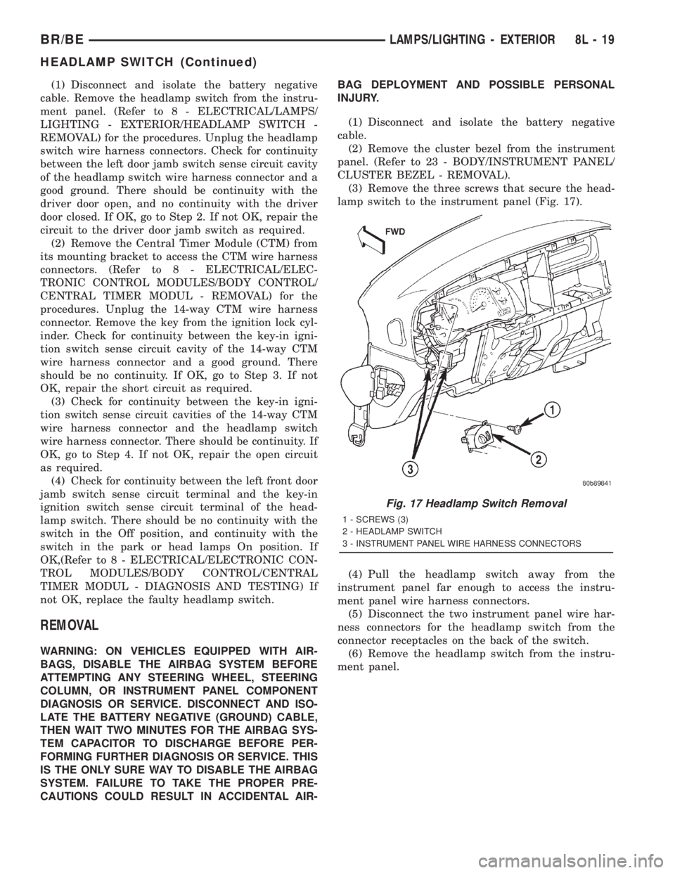
(3) Remove the three screws that secure the head-
lamp switch to the instrument panel (Fig. 17).
(4) Pull the headlamp switch away from the
instrument panel far enough to access the instru-
ment panel wire harness connectors.
(5) Disconnect the two instrument panel wire har-
ness connectors for the headlamp switch from the
connector receptacles on the back of the switch.
(6) Remove the headlamp switch from the instru-
ment panel.
Fig. 17 Headlamp Switch Removal
1 - SCREWS (3)
2 - HEADLAMP SWITCH
3 - INSTRUMENT PANEL WIRE HARNESS CONNECTORS
BR/BELAMPS/LIGHTING - EXTERIOR 8L - 19
HEADLAMP SWITCH (Continued)
Page 621 of 2889
includes momentary switching of the headlamp high
beam circuits to provide an optical horn feature
(sometimes referred to as flash-to-pass), which allows
the vehicle operator to momentarily flash the head-
lamp high beams as an optical signalling device.
²Intermittent Wipe Mode- The control knob of
the multi-function switch provides an intermittent
wipe mode with multiple delay interval positions.
²Turn Signal Control- The internal circuitry
and hardware of the multi-function switch provide
both momentary non-detent switching and detent
switching with automatic cancellation for both the
left and right turn signals.
²Washer Mode- A button on the end of the con-
trol stalk of the multi-function switch provides
washer system operation when the button is
depressed towards the steering column.
The multi-function switch cannot be adjusted or
repaired. If any function of the switch is faulty, or if
the switch is damaged, the entire switch unit must
be replaced.
OPERATION
The multi-function switch uses conventionally
switched outputs and a variable resistor to control
the many functions and features it provides using
hard wired circuitry. The switch is grounded at all
times through a single wire take out with an eyelet
terminal connector of the instrument panel wire har-
ness that is secured by a nut to a ground stud
located on the instrument panel armature, just above
and to the left of the glove box opening. When the
ignition switch is in the Accessory or On positions,
battery current from a fuse in the Junction Block
(JB) is provided through a fused ignition switch out-
put (run-acc) circuit. Following are descriptions of
the how the multi-function switch operates to control
the many functions and features it provides:
²Continuous Wipe Modes- When the control
knob of the multi-function switch is rotated to the
High or Low positions, the circuitry within the
switch provides a battery current output directly to
the high or low speed brush of the wiper motor.
When the control knob is in the Off position, the cir-
cuitry within the switch connects the output of the
wiper motor park switch to the low speed brush of
the wiper motor.
²Hazard Warning Control- The hazard warn-
ing push button is pushed down to unlatch the
switch and activate the hazard warning system, and
pushed down again to latch the switch and turn the
system off. When the hazard warning switch is
latched (hazard warning off), the push button will be
in a lowered position on the top of the steering col-
umn shroud; and, when the hazard warning switch is
unlatched (hazard warning on), the push button willbe in a raised position. The multi-function switch
hazard warning circuitry simultaneously provides a
signal to the hazard warning sense of the combina-
tion flasher to activate or deactivate the flasher out-
put, and directs the output of the flasher to the
hazard warning lamps.
²Headlamp Beam Selection- The multi-func-
tion switch control stalk is pulled towards the steer-
ing wheel past a detent, then released to actuate the
headlamp beam selection switch. Each time the con-
trol stalk is actuated in this manner, the opposite
headlamp mode from what is currently selected will
be activated. The internal circuitry of the headlamp
beam selection switch directs the output of the head-
lamp switch through hard wired circuitry to activate
the selected headlamp beam.
²Headlamp Optical Horn- The left multi-func-
tion switch control stalk is pulled towards the steer-
ing wheel to just before a detent, to momentarily
activate the headlamp high beams. The high beams
will remain illuminated until the control stalk is
released. The internal circuitry of the headlamp
beam selection switch provides a momentary ground
path to the headlamp high beams.
²Intermittent Wipe Mode- When the multi-
function switch control knob is rotated to the Delay
position, the circuitry within the switch connects the
output of the wiper motor relay to the low speed
brush of the wiper motor and provides a battery cur-
rent signal to the Central Timer Module (CTM). If
the Delay mode is selected, the control knob can then
be rotated to multiple minor detent positions, which
actuates a variable resistor within the switch and
provides a hard wired output to the CTM that sig-
nals the desired delay interval for the intermittent
wiper feature.
²Turn Signal Control- The multi-function
switch control stalk actuates the turn signal switch.
When the control stalk is moved in the upward direc-
tion, the right turn signal circuitry is activated; and,
when the control stalk is moved in the downward
direction, the left turn signal circuitry is activated.
The multi-function switch turn signal circuitry simul-
taneously provides a signal to the turn signal sense
of the combination flasher to activate or deactivate
the flasher output, and directs the output of the
flasher to the proper turn signal lamps. The turn sig-
nal switch has a detent position in each direction
that provides turn signals with automatic cancella-
tion, and an intermediate, momentary position in
each direction that provides turn signals only until
the left multi-function switch control stalk is
released. When the control stalk is moved to a turn
signal switch detent position, the cancel actuator
extends toward the center of the steering column. A
turn signal cancel cam that is integral to the clock-
8L - 24 LAMPS/LIGHTING - EXTERIORBR/BE
MULTI-FUNCTION SWITCH (Continued)
Page 625 of 2889
INSTALLATION
WARNING: ON VEHICLES EQUIPPED WITH AIR-
BAGS, DISABLE THE AIRBAG SYSTEM BEFORE
ATTEMPTING ANY STEERING WHEEL, STEERING
COLUMN, OR INSTRUMENT PANEL COMPONENT
DIAGNOSIS OR SERVICE. DISCONNECT AND ISO-
LATE THE BATTERY NEGATIVE (GROUND) CABLE,
THEN WAIT TWO MINUTES FOR THE AIRBAG SYS-
TEM CAPACITOR TO DISCHARGE BEFORE PER-
FORMING FURTHER DIAGNOSIS OR SERVICE. THIS
IS THE ONLY SURE WAY TO DISABLE THE AIRBAG
SYSTEM. FAILURE TO TAKE THE PROPER PRE-
CAUTIONS COULD RESULT IN ACCIDENTAL AIR-
BAG DEPLOYMENT AND POSSIBLE PERSONAL
INJURY.
(1) Position the multi-function switch next to the
steering column.
(2) Reconnect the instrument panel wire harness
connector for the multi-function switch to the switch
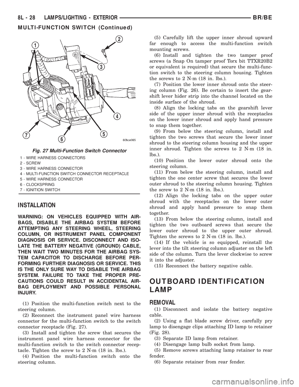
connector receptacle (Fig. 27).
(3) Install and tighten the screw that secures the
instrument panel wire harness connector for the
multi-function switch to the switch connector recep-
tacle. Tighten the screw to 2 N´m (18 in. lbs.).
(4) Position the multi-function switch onto the
steering column.(5) Carefully lift the upper inner shroud upward
far enough to access the multi-function switch
mounting screws.
(6) Install and tighten the two tamper proof
screws (a Snap On tamper proof Torx bit TTXR20B2
or equivalent is required) that secure the multi-func-
tion switch to the steering column housing. Tighten
the screws to 2 N´m (18 in. lbs.).
(7) Position the lower inner shroud onto the steer-
ing column (Fig. 26). Be certain to insert the gear-
shift lever hider strip into the channel located on the
inside surface of the shroud.
(8) Align the locking tabs on the gearshift lever
side of the upper inner shroud with the receptacles
on the lower inner shroud and apply hand pressure
to snap them together.
(9) From below the steering column, install and
tighten the two screws that secure the lower inner
shroud to the steering column housing and the upper
inner shroud. Tighten the screws to 2 N´m (18 in.
lbs.).
(10) Position the lower outer shroud onto the
steering column.
(11) From below the steering column, install and
tighten the one center screw that secures the lower
outer shroud to the steering column housing. Tighten
the screw to 2 N´m (18 in. lbs.).
(12) Align the locking tabs on the upper outer
shroud with the receptacles on the lower outer
shroud and apply hand pressure to snap them
together.
(13) From below the steering column, install and
tighten the two outboard screws that secure the
lower outer shroud to the upper outer shroud.
Tighten the screws to 2 N´m (18 in. lbs.).
(14) If the vehicle is so equipped, reinstall the
lever into the tilt steering column adjuster on the left
side of the column. Turn the lever clockwise to screw
it into the adjuster.
(15) Reconnect the battery negative cable.
OUTBOARD IDENTIFICATION
LAMP
REMOVAL
(1) Disconnect and isolate the battery negative
cable.
(2) Using a flat blade screw driver, carefully pry
lamp to disengage clips attaching ID lamp to retainer
(Fig. 28).
(3) Separate ID lamp from retainer.
(4) Disengage lamp bulb socket from lamp.
(5) Remove screws attaching lamp retainer to rear
fender.
(6) Separate retainer from rear fender.
Fig. 27 Multi-Function Switch Connector
1 - WIRE HARNESS CONNECTORS
2 - SCREW
3 - WIRE HARNESS CONNECTOR
4 - MULTI-FUNCTION SWITCH CONNECTOR RECEPTACLE
5 - WIRE HARNESS CONNECTOR
6 - CLOCKSPRING
7 - IGNITION SWITCH
8L - 28 LAMPS/LIGHTING - EXTERIORBR/BE
MULTI-FUNCTION SWITCH (Continued)
Page 677 of 2889
²Clockspring- The clockspring is located near
the top of the steering column, directly beneath the
steering wheel.
²Driver Airbag- The driver airbag is located in
the center of the steering wheel, beneath the driver
airbag trim cover.
²Driver Knee Blocker- The driver knee blocker
is a molded plastic structural unit secured to the
back side of and integral to the instrument panel
steering column opening cover.
²Passenger Airbag- The passenger airbag is
located on the instrument panel, beneath the passen-
ger airbag door on the instrument panel above the
glove box on the passenger side of the vehicle.
²Passenger Airbag On/Off Switch- The pas-
senger airbag on/off switch is located in a dedicated
opening in the upper right corner of the instrument
panel cluster bezel, to the right of the center panel
outlets of the climate control system.
²Passenger Knee Blocker- The passenger knee
blocker is a structural reinforcement that is integral
to and concealed within the glove box door.
The ACM and the EMIC each contain a central
processing unit and programming that allow them to
communicate with each other using the Chrysler Col-
lision Detection (CCD) data bus network. This
method of communication is used for control of the
airbag indicator on all models. (Refer to 8 - ELEC-
TRICAL/ELECTRONIC CONTROL MODULES/
COMMUNICATION - DESCRIPTION).
Hard wired circuitry connects the airbag system
components to each other through the electrical sys-
tem of the vehicle. These hard wired circuits are
integral to several wire harnesses, which are routed
throughout the vehicle and retained by many differ-
ent methods. These circuits may be connected to each
other, to the vehicle electrical system, and to the air-
bag system components through the use of a combi-
nation of soldered splices, splice block connectors,and many different types of wire harness terminal
connectors and insulators. Refer to the appropriate
wiring information. The wiring information includes
wiring diagrams, proper wire and connector repair
procedures, further details on wire harness routing
and retention, as well as pin-out and location views
for the various wire harness connectors, splices and
grounds.
OPERATION
The airbag system is referred to as a supplemental
restraint system because it was designed and is
intended to enhance the protection for the front seat
occupants of the vehicleonlywhen used in conjunc-
tion with the seat belts. It is referred to as a passive
system because the vehicle occupants are not
required to do anything to make it work. The pri-
mary passenger restraints in this or any other vehi-
cle are the standard equipment factory-installed seat
belts. Seat belts are referred to as an active restraint
because the vehicle occupants are required to physi-
cally fasten and properly adjust these restraints in
order to benefit from them. The vehicle occupants
must be wearing their seat belts in order to obtain
the maximum safety benefit from the factory-in-
stalled airbag system.
The airbag system electrical circuits are continu-
ously monitored and controlled by a microprocessor
and software contained within the Airbag Control
Module (ACM). An airbag indicator in the ElectroMe-
chanical Instrument Cluster (EMIC) lights for about
seven seconds as a bulb test each time the ignition
switch is turned to the On or Start positions. Follow-
ing the bulb test, the airbag indicator is turned on or
off by the ACM to indicate the status of the airbag
system. If the airbag indicator comes on at any time
other than during the bulb test, it indicates that
there is a problem in the airbag system electrical cir-
cuits. Such a problem may cause the airbags not to
deploy when required, or to deploy when not
required.
The clockspring on the top of the steering column
allows a continuous electrical circuit to be main-
tained between the stationary steering column and
the driver airbag inflator, which rotates with the
steering wheel. The passenger airbag on/off switch
allows the passenger side airbag to be disabled when
circumstances necessitate that a child, or an adult
with certain medical conditions be placed in the front
passenger seating position. Refer to the owner's man-
ual in the vehicle glove box for specific recommenda-
tions concerning the specific circumstances where the
passenger airbag on/off switch should be used to dis-
able the passenger airbag.
Fig. 1 SRS Logo
8O - 2 RESTRAINTSBR/BE
RESTRAINTS (Continued)
Page 680 of 2889
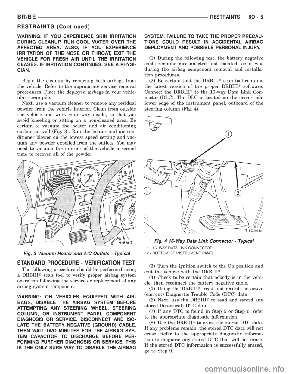
WARNING: IF YOU EXPERIENCE SKIN IRRITATION
DURING CLEANUP, RUN COOL WATER OVER THE
AFFECTED AREA. ALSO, IF YOU EXPERIENCE
IRRITATION OF THE NOSE OR THROAT, EXIT THE
VEHICLE FOR FRESH AIR UNTIL THE IRRITATION
CEASES. IF IRRITATION CONTINUES, SEE A PHYSI-
CIAN.
Begin the cleanup by removing both airbags from
the vehicle. Refer to the appropriate service removal
procedures. Place the deployed airbags in your vehic-
ular scrap pile.
Next, use a vacuum cleaner to remove any residual
powder from the vehicle interior. Clean from outside
the vehicle and work your way inside, so that you
avoid kneeling or sitting on a non-cleaned area. Be
certain to vacuum the heater and air conditioning
outlets as well (Fig. 3). Run the heater and air con-
ditioner blower on the lowest speed setting and vac-
uum any powder expelled from the outlets. You may
need to vacuum the interior of the vehicle a second
time to recover all of the powder.
STANDARD PROCEDURE - VERIFICATION TEST
The following procedure should be performed using
a DRBIIItscan tool to verify proper airbag system
operation following the service or replacement of any
airbag system component.
WARNING: ON VEHICLES EQUIPPED WITH AIR-
BAGS, DISABLE THE AIRBAG SYSTEM BEFORE
ATTEMPTING ANY STEERING WHEEL, STEERING
COLUMN, OR INSTRUMENT PANEL COMPONENT
DIAGNOSIS OR SERVICE. DISCONNECT AND ISO-
LATE THE BATTERY NEGATIVE (GROUND) CABLE,
THEN WAIT TWO MINUTES FOR THE AIRBAG SYS-
TEM CAPACITOR TO DISCHARGE BEFORE PER-
FORMING FURTHER DIAGNOSIS OR SERVICE. THIS
IS THE ONLY SURE WAY TO DISABLE THE AIRBAGSYSTEM. FAILURE TO TAKE THE PROPER PRECAU-
TIONS COULD RESULT IN ACCIDENTAL AIRBAG
DEPLOYMENT AND POSSIBLE PERSONAL INJURY.
(1) During the following test, the battery negative
cable remains disconnected and isolated, as it was
during the airbag component removal and installa-
tion procedures.
(2) Be certain that the DRBIIItscan tool contains
the latest version of the proper DRBIIItsoftware.
Connect the DRBIIItto the 16-way Data Link Con-
nector (DLC). The DLC is located on the driver side
lower edge of the instrument panel, outboard of the
steering column (Fig. 4).
(3) Turn the ignition switch to the On position and
exit the vehicle with the DRBIIIt.
(4) Check to be certain that nobody is in the vehi-
cle, then reconnect the battery negative cable.
(5) Using the DRBIIIt, read and record the active
(current) Diagnostic Trouble Code (DTC) data.
(6) Next, use the DRBIIItto read and record any
stored (historical) DTC data.
(7) If any DTC is found in Step 5 or Step 6, refer
to the appropriate diagnostic information.
(8) Use the DRBIIItto erase the stored DTC data.
If any problems remain, the stored DTC data will not
erase. Refer to the appropriate diagnostic informa-
tion to diagnose any stored DTC that will not erase.
If the stored DTC information is successfully erased,
go to Step 9.
Fig. 3 Vacuum Heater and A/C Outlets - Typical
Fig. 4 16-Way Data Link Connector - Typical
1 - 16±WAY DATA LINK CONNECTOR
2 - BOTTOM OF INSTRUMENT PANEL
BR/BERESTRAINTS 8O - 5
RESTRAINTS (Continued)
Page 699 of 2889
switch is in its installed position, the only compo-
nents visible through the dedicated opening of the
cluster bezel are the switch face plate and nomencla-
ture, the key cylinder actuator, and a small round
lens with the text9Off9imprinted on it. The ªOnº
position of the switch is designated by text imprinted
upon the face plate of the switch, but is not illumi-
nated. The remainder of the switch is concealed
behind the switch face plate and the instrument
panel cluster bezel.
The passenger airbag on-off switch housing is con-
structed of molded plastic and has three integral
mounting tabs. These mounting tabs are used to
secure the switch to the back of the molded plastic
switch face plate with three small screws. The
molded plastic face plate also has three integral
mounting tabs that are used to secure the switch and
face plate unit to the instrument panel carrier with
three additional screws. Two short pigtail wires with
molded plastic connector insulators exit the back of
the switch housing and connect the switch to the
vehicle electrical system through two dedicated take
outs of the instrument panel wire harness. The har-
ness take outs are equipped with molded plastic con-
nector insulators that are keyed and latched to
ensure proper and secure switch electrical connec-
tions. The passenger airbag on/off switch cannot be
adjusted or repaired and, if faulty or damaged, the
switch must be replaced.
OPERATION
The passenger airbag on-off switch allows the cus-
tomer to turn the passenger airbag function On or
Off to accommodate certain uses of the right front
seating position where airbag protection may not be
desired. See the owner's manual in the vehicle glove
box for specific recommendations on when to enable
or disable the passenger airbag. The Off indicator of
the switch will be illuminated whenever the switch is
turned to the Off position. The ignition key is the
only key or object that should ever be inserted into
the switch. The on-off switch requires only a partial
key insertion to fully depress a spring-loaded locking
plunger. The spring-loaded locking plunger prevents
the user from leaving the key in the switch. The key
will be automatically ejected when force is not
applied. To actuate the passenger side airbag on/off
switch, insert the ignition key into the switch key
actuator far enough to fully depress the plunger and
rotate to the desired switch position. When the
switch key actuator is rotated to its clockwise stop
(the key actuator slot will be aligned with the Off
indicator lamp), the Off indicator is illuminated and
the passenger airbag is disabled. When the switch is
rotated to its counterclockwise stop (the key actuator
slot will be in a vertical position), the Off indicatorwill be extinguished and the passenger airbag is
enabled.
The passenger airbag switch is connected in series
between the Airbag Control Module (ACM) and the
passenger airbag inflator unit. When the switch is in
the On position, the switch connects the ACM
directly to the passenger airbag inflator. When the
switch is in the Off position it interrupts the inflator
circuits, but replaces the normal resistance in these
circuits with an internal resistor. Thus, the ACM is
unable to distinguish the mode of the switch and still
sends an electrical signal as though it were deploying
the passenger airbag when it detects a sufficient
impact. However, the switch position should not be
changed while the ignition switch is in the On posi-
tion, as the ACM may detect a fault, record a Diag-
nostic Trouble Code (DTC), and illuminate the Airbag
indicator in response to a momentary open it senses
in the passenger airbag inflator circuits as the on/off
switch changes states.
REMOVAL
WARNING: DISABLE THE AIRBAG SYSTEM
BEFORE ATTEMPTING ANY STEERING WHEEL,
STEERING COLUMN, OR INSTRUMENT PANEL
COMPONENT DIAGNOSIS OR SERVICE. DISCON-
NECT AND ISOLATE THE BATTERY NEGATIVE
(GROUND) CABLE, THEN WAIT TWO MINUTES FOR
THE AIRBAG SYSTEM CAPACITOR TO DISCHARGE
BEFORE PERFORMING FURTHER DIAGNOSIS OR
SERVICE. THIS IS THE ONLY SURE WAY TO DIS-
ABLE THE AIRBAG SYSTEM. FAILURE TO TAKE
THE PROPER PRECAUTIONS COULD RESULT IN
ACCIDENTAL AIRBAG DEPLOYMENT AND POSSI-
BLE PERSONAL INJURY.
(1) Disconnect and isolate the battery negative
cable. If either of the airbags has not been deployed,
wait two minutes for the system capacitor to dis-
charge before further service.
(2) Remove the cluster bezel from the instrument
panel. (Refer to 23 - BODY/INSTRUMENT PANEL/
CLUSTER BEZEL - REMOVAL).
(3) Remove the glove box from the instrument
panel. (Refer to 23 - BODY/INSTRUMENT PANEL/
GLOVE BOX - REMOVAL).
(4) Reach through the glove box opening to access
and disconnect the two passenger airbag on/off
switch pigtail wire harness connectors from the
instrument panel wire harness connectors. These
connectors are retained on a bracket located on the
inboard glove box opening reinforcement (Fig. 20).
(5) Remove the three screws that secure the pas-
senger airbag on/off switch face plate to the instru-
ment panel (Fig. 21).
8O - 24 RESTRAINTSBR/BE
PASSENGER AIRBAG ON/OFF SWITCH (Continued)