Ground terminals DODGE RAM 2001 Service Owner's Manual
[x] Cancel search | Manufacturer: DODGE, Model Year: 2001, Model line: RAM, Model: DODGE RAM 2001Pages: 2889, PDF Size: 68.07 MB
Page 614 of 2889
terminal. The ISO terminal designations are as fol-
lows:
²30 (Common Feed)- This terminal is con-
nected to the movable contact point of the relay.
²85 (Coil Ground)- This terminal is connected
to the ground feed side of the relay control coil.
²86 (Coil Battery)- This terminal is connected
to the battery feed side of the relay control coil.
²87 (Normally Open)- This terminal is con-
nected to the normally open fixed contact point of the
relay.
²87A (Normally Closed)- This terminal is con-
nected to the normally closed fixed contact point of
the relay.
The headlamp relay cannot be adjusted or
repaired. If the relay is damaged or faulty, it must be
replaced.
OPERATION
The headlamp (or security) relay is an electrome-
chanical switch that uses a low current input from
the high-line or premium Central Timer Module
(CTM) to control a high current output to the head-
lamps. The movable common feed contact point is
held against the fixed normally closed contact point
by spring pressure. When the relay coil is energized,
an electromagnetic field is produced by the coil wind-
ings. This electromagnetic field draws the movable
relay contact point away from the fixed normally
closed contact point, and holds it against the fixed
normally open contact point. When the relay coil is
de-energized, spring pressure returns the movable
contact point back against the fixed normally closed
contact point. A resistor or diode is connected in par-
allel with the relay coil in the relay, and helps to dis-
sipate voltage spikes and electromagneticinterference that can be generated as the electromag-
netic field of the relay coil collapses.
The headlamp relay terminals are connected to the
vehicle electrical system through a connector recepta-
cle in the Power Distribution Center (PDC). The
inputs and outputs of the headlamp relay include:
²The common feed terminal (30) is connected to
ground at all times through a take out and eyelet
terminal connector of the right headlamp and dash
wire harness that is secured by a ground screw to
the left fender inner shield near the PDC in the
engine compartment.
²The coil ground terminal (85) is connected to the
Central Timer Module (CTM) through the security
relay control circuit. The CTM energizes the head-
lamp relay control coil by internally pulling this cir-
cuit to ground.
²The coil battery terminal (86) is connected to
battery current at all times through a fused B(+) cir-
cuit that is internal to the PDC.
²The normally open terminal (87) is connected to
the headlamps at all times through the beam select
switch low beam output circuit. This circuit provides
a path to ground for the headlamps through the com-
mon feed terminal when the headlamp relay control
coil is energized by the CTM.
²The normally closed terminal (87A) is not con-
nected to any circuit in this application, but is
grounded through the common feed terminal when
the headlamp relay control coil is de-energized.
The headlamp relay can be diagnosed using con-
ventional diagnostic tools and methods.
DIAGNOSIS AND TESTING - HEADLAMP RELAY
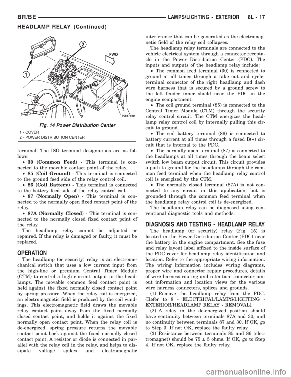
The headlamp (or security) relay (Fig. 15) is
located in the Power Distribution Center (PDC) near
the battery in the engine compartment. See the fuse
and relay layout label affixed to the inside surface of
the PDC cover for headlamp relay identification and
location. Refer to the appropriate wiring information.
The wiring information includes wiring diagrams,
proper wire and connector repair procedures, details
of wire harness routing and retention, connector pin-
out information and location views for the various
wire harness connectors, splices and grounds.
(1) Remove the headlamp relay from the PDC.
(Refer to 8 - ELECTRICAL/LAMPS/LIGHTING -
EXTERIOR/HEADLAMP RELAY - REMOVAL).
(2) A relay in the de-energized position should
have continuity between terminals 87A and 30, and
no continuity between terminals 87 and 30. If OK, go
to Step 3. If not OK, replace the faulty relay.
(3) Resistance between terminals 85 and 86 (elec-
tromagnet) should be 75 5 ohms. If OK, go to Step
4. If not OK, replace the faulty relay.
Fig. 14 Power Distribution Center
1 - COVER
2 - POWER DISTRIBUTION CENTER
BR/BELAMPS/LIGHTING - EXTERIOR 8L - 17
HEADLAMP RELAY (Continued)
Page 615 of 2889
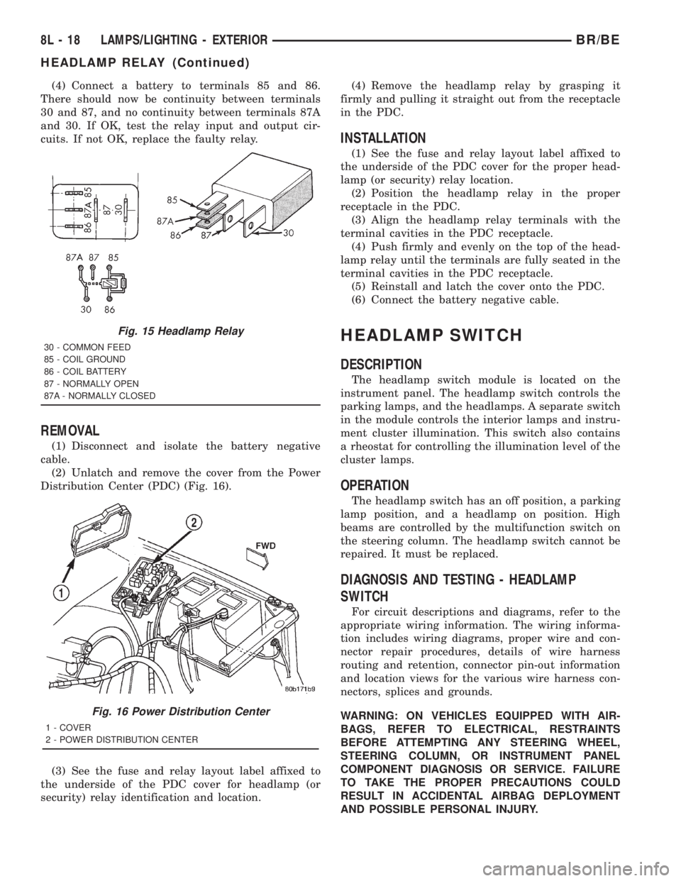
(4) Connect a battery to terminals 85 and 86.
There should now be continuity between terminals
30 and 87, and no continuity between terminals 87A
and 30. If OK, test the relay input and output cir-
cuits. If not OK, replace the faulty relay.
REMOVAL
(1) Disconnect and isolate the battery negative
cable.
(2) Unlatch and remove the cover from the Power
Distribution Center (PDC) (Fig. 16).
(3) See the fuse and relay layout label affixed to
the underside of the PDC cover for headlamp (or
security) relay identification and location.(4) Remove the headlamp relay by grasping it
firmly and pulling it straight out from the receptacle
in the PDC.
INSTALLATION
(1) See the fuse and relay layout label affixed to
the underside of the PDC cover for the proper head-
lamp (or security) relay location.
(2) Position the headlamp relay in the proper
receptacle in the PDC.
(3) Align the headlamp relay terminals with the
terminal cavities in the PDC receptacle.
(4) Push firmly and evenly on the top of the head-
lamp relay until the terminals are fully seated in the
terminal cavities in the PDC receptacle.
(5) Reinstall and latch the cover onto the PDC.
(6) Connect the battery negative cable.
HEADLAMP SWITCH
DESCRIPTION
The headlamp switch module is located on the
instrument panel. The headlamp switch controls the
parking lamps, and the headlamps. A separate switch
in the module controls the interior lamps and instru-
ment cluster illumination. This switch also contains
a rheostat for controlling the illumination level of the
cluster lamps.
OPERATION
The headlamp switch has an off position, a parking
lamp position, and a headlamp on position. High
beams are controlled by the multifunction switch on
the steering column. The headlamp switch cannot be
repaired. It must be replaced.
DIAGNOSIS AND TESTING - HEADLAMP
SWITCH
For circuit descriptions and diagrams, refer to the
appropriate wiring information. The wiring informa-
tion includes wiring diagrams, proper wire and con-
nector repair procedures, details of wire harness
routing and retention, connector pin-out information
and location views for the various wire harness con-
nectors, splices and grounds.
WARNING: ON VEHICLES EQUIPPED WITH AIR-
BAGS, REFER TO ELECTRICAL, RESTRAINTS
BEFORE ATTEMPTING ANY STEERING WHEEL,
STEERING COLUMN, OR INSTRUMENT PANEL
COMPONENT DIAGNOSIS OR SERVICE. FAILURE
TO TAKE THE PROPER PRECAUTIONS COULD
RESULT IN ACCIDENTAL AIRBAG DEPLOYMENT
AND POSSIBLE PERSONAL INJURY.
Fig. 15 Headlamp Relay
30 - COMMON FEED
85 - COIL GROUND
86 - COIL BATTERY
87 - NORMALLY OPEN
87A - NORMALLY CLOSED
Fig. 16 Power Distribution Center
1 - COVER
2 - POWER DISTRIBUTION CENTER
8L - 18 LAMPS/LIGHTING - EXTERIORBR/BE
HEADLAMP RELAY (Continued)
Page 622 of 2889
spring mechanism rotates with the steering wheel
and the cam lobes contact the cancel actuator when
it is extended from the multi-function switch. When
the steering wheel is rotated during a turning
maneuver, one of the two turn signal cancel cam
lobes will contact the turn signal cancel actuator. The
cancel actuator latches against the cancel cam rota-
tion in the direction opposite that which is signaled.
In other words, if the left turn signal detent is
selected, the lobes of the cancel cam will ratchet past
the cancel actuator when the steering wheel is
rotated to the left, but will unlatch the cancel actua-
tor as the steering wheel rotates to the right and
returns to center, which will cancel the turn signal
event and release the control stalk from the detent so
it returns to the neutral Off position.
²Washer Mode- Pushing the button on the end
of the multi-function switch control knob towards the
steering column provides a battery current output
through the momentary single pole, single throw
washer switch circuitry to operate the washer pump/
motor and provides a signal to the CTM. If the wip-
ers are not operating when the washer switch is
actuated, the CTM will operate the wiper motor for
as long as the washer switch is depressed plus about
three additional wipe cycles. If the wipers are oper-
ating in the intermittent mode when the washer
switch is actuated, the CTM will operate the wiper
motor at a fixed low speed for as long as the washer
switch is depressed plus about three additional wipe
cycles before the wipers return to the selected inter-
mittent wipe interval.DIAGNOSIS AND TESTING - MULTI-FUNCTION
SWITCH
Refer to the appropriate wiring information. The
wiring information includes wiring diagrams, proper
wire and connector repair procedures, details of wire
harness routing and retention, connector pin-out
information and location views for the various wire
harness connectors, splices and grounds.
WARNING: ON VEHICLES EQUIPPED WITH AIR-
BAGS, DISABLE THE AIRBAG SYSTEM BEFORE
ATTEMPTING ANY STEERING WHEEL, STEERING
COLUMN, OR INSTRUMENT PANEL COMPONENT
DIAGNOSIS OR SERVICE. DISCONNECT AND ISO-
LATE THE BATTERY NEGATIVE (GROUND) CABLE,
THEN WAIT TWO MINUTES FOR THE AIRBAG SYS-
TEM CAPACITOR TO DISCHARGE BEFORE PER-
FORMING FURTHER DIAGNOSIS OR SERVICE. THIS
IS THE ONLY SURE WAY TO DISABLE THE AIRBAG
SYSTEM. FAILURE TO TAKE THE PROPER PRE-
CAUTIONS COULD RESULT IN ACCIDENTAL AIR-
BAG DEPLOYMENT AND POSSIBLE PERSONAL
INJURY.
(1) Disconnect and isolate the battery negative
cable. Disconnect the instrument panel wire harness
connector from the multi-function switch connector
receptacle.
(2) Using an ohmmeter, perform the continuity
and resistance tests at the terminals in the multi-
function switch connector receptacle as shown in the
Multi-Function Switch Tests chart (Fig. 25).
BR/BELAMPS/LIGHTING - EXTERIOR 8L - 25
MULTI-FUNCTION SWITCH (Continued)
Page 631 of 2889
DOOR AJAR SWITCH
DESCRIPTION
The door ajar switches are mounted to the door
hinge pillars. The switches close a path to ground for
the Central Timer Module (CTM) when a door is
opened, and open the ground path when a door is
closed.
The door ajar switches cannot be repaired and, if
faulty or damaged, they must be replaced.
DIAGNOSIS AND TESTING - DOOR AJAR
SWITCH
For circuit descriptions and diagrams, refer to the
appropriate wiring information. The wiring informa-tion includes wiring diagrams, proper wire and con-
nector repair procedures, details of wire harness
routing and retention, connector pin-out information
and location views for the various wire harness con-
nectors, splices and grounds.
WARNING: ON VEHICLES EQUIPPED WITH AIR-
BAGS, REFER TO ELECTRICAL, RESTRAINTS
BEFORE ATTEMPTING ANY STEERING WHEEL,
STEERING COLUMN, OR INSTRUMENT PANEL
COMPONENT DIAGNOSIS OR SERVICE. FAILURE
TO TAKE THE PROPER PRECAUTIONS COULD
RESULT IN ACCIDENTAL AIRBAG DEPLOYMENT
AND POSSIBLE PERSONAL INJURY.
(1) Rotate the headlamp switch knob counterclock-
wise to ensure that the dome lamps are not switched
off. Open the driver door and note whether the inte-
rior lamps light. They should light. If OK, (Refer to 8
- ELECTRICAL/LAMPS/LIGHTING - EXTERIOR/
HEADLAMP SWITCH - DIAGNOSIS AND TEST-
ING). If not OK, go to Step 2.
(2) Disconnect and isolate the battery negative
cable. Unplug the driver door ajar switch from its
wire harness connector. Check for continuity between
the ground circuit cavity of the driver door ajar
switch wire harness connector and a good ground.
There should be continuity. If OK, go to Step 3. If not
OK, repair the circuit to ground as required.
(3) Check for continuity between the door ajar
switch ground circuit terminal and each of the other
two terminals of the driver door ajar switch. There
should be continuity with the switch plunger
released, and no continuity with the switch plunger
depressed. If OK, go to Step 4. If not OK, replace the
faulty switch.
(4) Remove the Central Timer Module (CTM) from
its mounting bracket to access the CTM wire harness
connectors (Refer to 8 - ELECTRICAL/ELECTRONIC
CONTROL MODULES/BODY CONTROL/CENTRAL
TIMER MODUL - REMOVAL). Unplug the 14-way
CTM wire harness connector. Check for continuity
between the driver door switch sense circuit cavity of
the 14-way CTM wire harness connector and a good
ground. There should be no continuity. If OK, go to
Step 5. If not OK, repair the short circuit as
required.
(5) Check for continuity between the driver door
switch sense circuit cavities of the 14-way CTM wire
harness connector and the driver door ajar switch
wire harness connector. There should be continuity. If
OK, (Refer to 8 - ELECTRICAL/LAMPS/LIGHTING -
EXTERIOR/HEADLAMP SWITCH - DIAGNOSIS
AND TESTING) If not OK, repair the open circuit as
required.
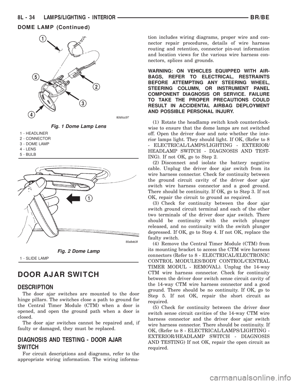
Fig. 1 Dome Lamp Lens
1 - HEADLINER
2 - CONNECTOR
3 - DOME LAMP
4 - LENS
5 - BULB
Fig. 2 Dome Lamp
1 - SLIDE LAMP
8L - 34 LAMPS/LIGHTING - INTERIORBR/BE
DOME LAMP (Continued)
Page 655 of 2889
DOOR CYLINDER LOCK SWITCH
Switch Position
Resistance
Driver Side Passenger Side
Neutral Neutral 12 Kilohms
Lock (Clockwise)Lock (Counter
Clockwise)644 Ohms
Unlock (Counter
Clockwise)Unlock
(Clockwise)1565 Ohms
(3)
If a door cylinder lock switch fails any of the
resistance tests, replace the faulty switch as required.
REMOVAL
(1) Disconnect and isolate the battery negative
cable.
(2) Remove the door outside latch handle mount-
ing hardware and linkage from the inside of the door.
(Refer to 23 - BODY/DOOR - FRONT/EXTERIOR
HANDLE - REMOVAL).
(3) From the outside of the door, pull the door out-
side latch handle out from the door far enough to
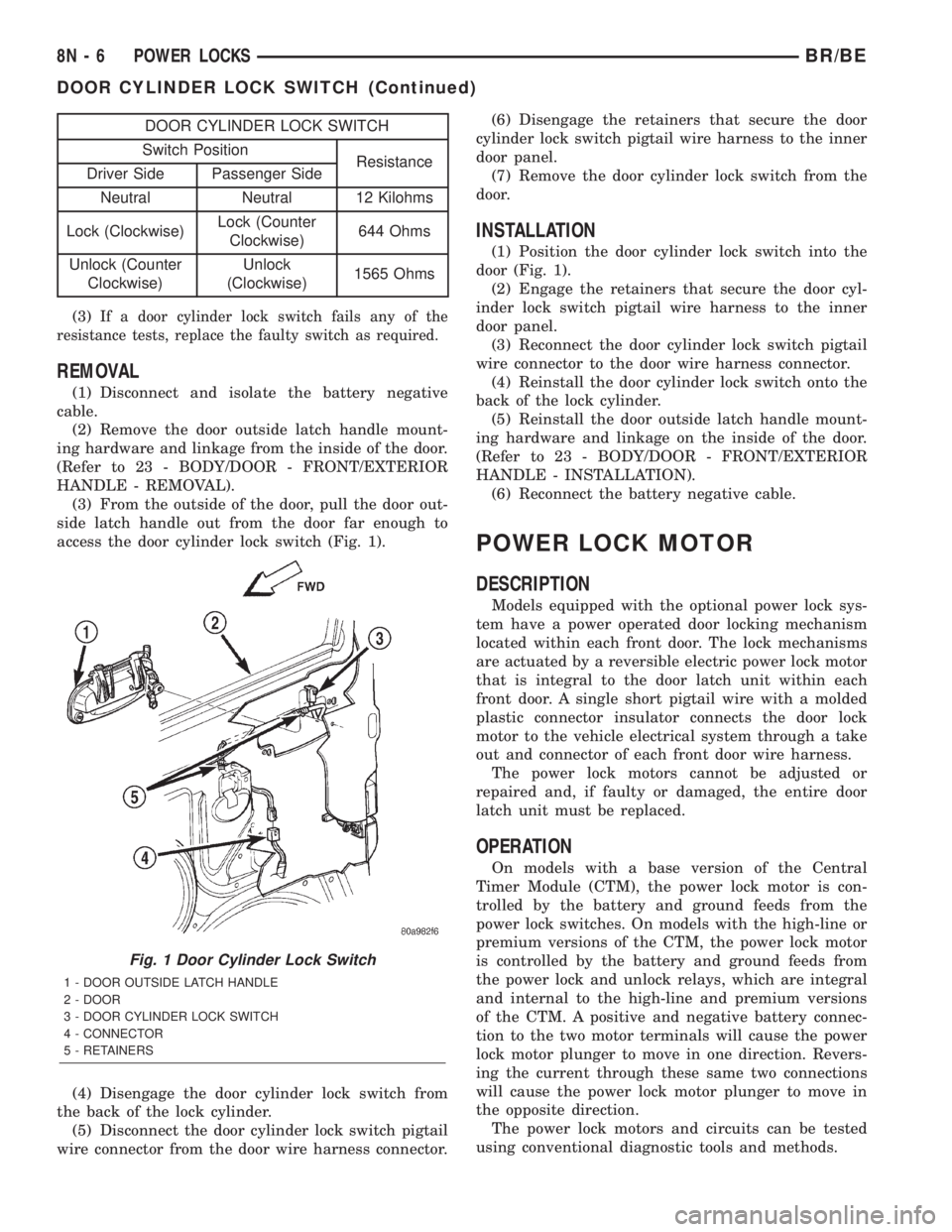
access the door cylinder lock switch (Fig. 1).
(4) Disengage the door cylinder lock switch from
the back of the lock cylinder.
(5) Disconnect the door cylinder lock switch pigtail
wire connector from the door wire harness connector.(6) Disengage the retainers that secure the door
cylinder lock switch pigtail wire harness to the inner
door panel.
(7) Remove the door cylinder lock switch from the
door.
INSTALLATION
(1) Position the door cylinder lock switch into the
door (Fig. 1).
(2) Engage the retainers that secure the door cyl-
inder lock switch pigtail wire harness to the inner
door panel.
(3) Reconnect the door cylinder lock switch pigtail
wire connector to the door wire harness connector.
(4) Reinstall the door cylinder lock switch onto the
back of the lock cylinder.
(5) Reinstall the door outside latch handle mount-
ing hardware and linkage on the inside of the door.
(Refer to 23 - BODY/DOOR - FRONT/EXTERIOR
HANDLE - INSTALLATION).
(6) Reconnect the battery negative cable.
POWER LOCK MOTOR
DESCRIPTION
Models equipped with the optional power lock sys-
tem have a power operated door locking mechanism
located within each front door. The lock mechanisms
are actuated by a reversible electric power lock motor
that is integral to the door latch unit within each
front door. A single short pigtail wire with a molded
plastic connector insulator connects the door lock
motor to the vehicle electrical system through a take
out and connector of each front door wire harness.
The power lock motors cannot be adjusted or
repaired and, if faulty or damaged, the entire door
latch unit must be replaced.
OPERATION
On models with a base version of the Central
Timer Module (CTM), the power lock motor is con-
trolled by the battery and ground feeds from the
power lock switches. On models with the high-line or
premium versions of the CTM, the power lock motor
is controlled by the battery and ground feeds from
the power lock and unlock relays, which are integral
and internal to the high-line and premium versions
of the CTM. A positive and negative battery connec-
tion to the two motor terminals will cause the power
lock motor plunger to move in one direction. Revers-
ing the current through these same two connections
will cause the power lock motor plunger to move in
the opposite direction.
The power lock motors and circuits can be tested
using conventional diagnostic tools and methods.
Fig. 1 Door Cylinder Lock Switch
1 - DOOR OUTSIDE LATCH HANDLE
2 - DOOR
3 - DOOR CYLINDER LOCK SWITCH
4 - CONNECTOR
5 - RETAINERS
8N - 6 POWER LOCKSBR/BE
DOOR CYLINDER LOCK SWITCH (Continued)
Page 675 of 2889
INSTALLATION
(1) Connect the power window switch to the har-
ness connector.
(2) Insert the rear of the switch and bezel unit into
the opening.
(3) Push down on the front of the switch until the
retaining tabs snap into place.
(4) Reconnect the battery negative cable.
WINDOW MOTOR
DESCRIPTION
A permanent magnet reversible motor moves the
window regulator through an integral gearbox mech-
anism. A positive and negative battery connection to
the two motor terminals will cause the motor to
rotate in one direction. Reversing the current
through these same two connections will cause the
motor to rotate in the opposite direction.
In addition, each power window motor is equipped
with an integral self-resetting circuit breaker to pro-
tect the motor from overloads. The power window
motor and gearbox assembly cannot be repaired and,
if faulty or damaged, the entire power window regu-
lator assembly must be replaced.
DIAGNOSIS AND TESTING - WINDOW MOTOR
For circuit descriptions and diagrams, refer to the
appropriate wiring information. The wiring informa-
tion includes wiring diagrams, proper wire and con-
nector repair procedures, details of wire harness
routing and retention, connector pin-out information
and location views for the various wire harness con-
nectors, splices and grounds. Before you proceed withthis diagnosis, confirm proper switch operation.
(Refer to 8 - ELECTRICAL/POWER WINDOWS/
POWER WINDOW SWITCH - DIAGNOSIS AND
TESTING).
(1) Disconnect and isolate the battery negative
cable. Remove the trim panel from the door with the
inoperative power window.
(2) Unplug the power window motor wire harness
connector. Apply 12 volts across the motor terminals
to check its operation in one direction. Reverse the
connections across the motor terminals to check the
operation in the other direction. Remember, if the
window is in the full up or full down position, the
motor will not operate in that direction by design. If
OK, repair the circuits from the power window motor
to the power window switch as required. If not OK,
replace the faulty motor.
(3) If the motor operates in both directions, check
the operation of the window glass and lift mechanism
through its complete up and down travel. There
should be no binding or sticking of the window glass
or lift mechanism through the entire travel range. If
not OK, (Refer to 23 - BODY/DOOR - FRONT/WIN-
DOW REGULATOR - REMOVAL).
REMOVAL
The power window motor and mechanism is inte-
gral to the power window regulator unit. If the power
window motor or mechanism is faulty or damaged,
the entire power window regulator unit must be
replaced. (Refer to 23 - BODY/DOOR - FRONT/WIN-
DOW REGULATOR - REMOVAL) for the window
regulator service procedures.
8N - 26 POWER WINDOWSBR/BE
POWER WINDOW SWITCH (Continued)
Page 738 of 2889
(6) Disconnect the headlamp and dash wire har-
ness connector for the wiper motor from the wiper
motor pigtail wire connector.
(7) Disconnect the headlamp and dash wire har-
ness ground connector from the wiper motor ground
terminal.
(8) Remove the wiper module from the cowl ple-
num as a unit.
INSTALLATION
(1) Position the wiper module into the cowl ple-
num as a unit.
(2) Reconnect the headlamp and dash wire harness
ground connector to the wiper motor ground terminal
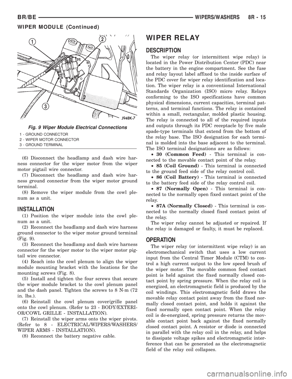
(Fig. 9).
(3) Reconnect the headlamp and dash wire harness
connector for the wiper motor to the wiper motor pig-
tail wire connector.
(4) Reach into the cowl plenum to align the wiper
module mounting bracket with the locations for the
mounting screws (Fig. 8).
(5) Install and tighten the four screws that secure
the wiper module bracket to the cowl plenum panel
and the dash panel. Tighten the screws to 8 N´m (72
in. lbs.).
(6) Reinstall the cowl plenum cover/grille panel
onto the cowl plenum. (Refer to 23 - BODY/EXTERI-
OR/COWL GRILLE - INSTALLATION).
(7) Reinstall the wiper arms onto the wiper pivots.
(Refer to 8 - ELECTRICAL/WIPERS/WASHERS/
WIPER ARMS - INSTALLATION).
(8) Reconnect the battery negative cable.
WIPER RELAY
DESCRIPTION
The wiper relay (or intermittent wipe relay) is
located in the Power Distribution Center (PDC) near
the battery in the engine compartment. See the fuse
and relay layout label affixed to the inside surface of
the PDC cover for wiper relay identification and loca-
tion. The wiper relay is a conventional International
Standards Organization (ISO) micro relay. Relays
conforming to the ISO specifications have common
physical dimensions, current capacities, terminal pat-
terns, and terminal functions. The relay is contained
within a small, rectangular, molded plastic housing.
The relay is connected to all of the required inputs
and outputs through its PDC receptacle by five male
spade-type terminals that extend from the bottom of
the relay base. The ISO designation for each termi-
nal is molded into the base adjacent to the terminal.
The ISO terminal designations are as follows:
²30 (Common Feed)- This terminal is con-
nected to the movable contact point of the relay.
²85 (Coil Ground)- This terminal is connected
to the ground feed side of the relay control coil.
²86 (Coil Battery)- This terminal is connected
to the battery feed side of the relay control coil.
²87 (Normally Open)- This terminal is con-
nected to the normally open fixed contact point of the
relay.
²87A (Normally Closed)- This terminal is con-
nected to the normally closed fixed contact point of
the relay.
The wiper relay cannot be adjusted or repaired. If
the relay is damaged or faulty, it must be replaced.
OPERATION
The wiper relay (or intermittent wipe relay) is an
electromechanical switch that uses a low current
input from the Central Timer Module (CTM) to con-
trol a high current output to the low speed brush of
the wiper motor. The movable common feed contact
point is held against the fixed normally closed con-
tact point by spring pressure. When the relay coil is
energized, an electromagnetic field is produced by the
coil windings. This electromagnetic field draws the
movable relay contact point away from the fixed nor-
mally closed contact point, and holds it against the
fixed normally open contact point. When the relay
coil is de-energized, spring pressure returns the mov-
able contact point back against the fixed normally
closed contact point. A resistor or diode is connected
in parallel with the relay coil in the relay, and helps
to dissipate voltage spikes and electromagnetic inter-
ference that can be generated as the electromagnetic
field of the relay coil collapses.
Fig. 9 Wiper Module Electrical Connections
1 - GROUND CONNECTOR
2 - WIPER MOTOR CONNECTOR
3 - GROUND TERMINAL
BR/BEWIPERS/WASHERS 8R - 15
WIPER MODULE (Continued)
Page 739 of 2889
The wiper relay terminals are connected to the
vehicle electrical system through a connector recepta-
cle in the Power Distribution Center (PDC). The
inputs and outputs of the wiper relay include:
²The common feed terminal (30) is connected to
the wiper motor low speed brush through the wiper
control circuitry of the multi-function switch on the
steering column. When the wiper relay is de-ener-
gized, the common feed terminal is connected to the
wiper park switch output through the wiper park
switch sense circuit. The wiper park switch output
may be battery current (wipers are not parked), or
ground (wipers are parked). When the wiper relay is
energized, the common feed terminal of the wiper is
connected to battery current from a fuse in the Junc-
tion Block (JB) through a fused ignition switch out-
put (run-acc) circuit.
²The coil ground terminal (85) is connected to the
relay control output of the CTM through the wiper
motor relay control circuit. The CTM controls the
ground path for this circuit internally to energize or
de-energize the wiper relay based upon its program-
ming and inputs from the wiper and washer control
circuitry of the multi-function switch and from the
wiper motor park switch.
²The coil battery terminal (86) is connected to
battery current from a fuse in the Junction Block
(JB) through a fused ignition switch output (run-acc)
circuit whenever the ignition switch is in the On or
Accessory positions.
²The normally open terminal (87) is connected to
battery current from a fuse in the Junction Block
(JB) through a fused ignition switch output (run-acc)
circuit whenever the wiper relay control coil is ener-
gized by the CTM. This circuit provides fused igni-
tion switch output (run-acc) current to the wiper
motor low speed brush only when the wiper relay
control coil is energized.
²The normally closed terminal (87A) is connected
to the output of the wiper motor park switch through
the wiper motor park switch sense circuit. This cir-
cuit provides battery current (wipers are not parked)
or ground (wipers are parked) to the wiper motor low
speed brush whenever the wiper relay control coil is
de-energized and the Off position of the wiper control
of the multi-function switch is selected.
The wiper relay can be diagnosed using conven-
tional diagnostic tools and methods.
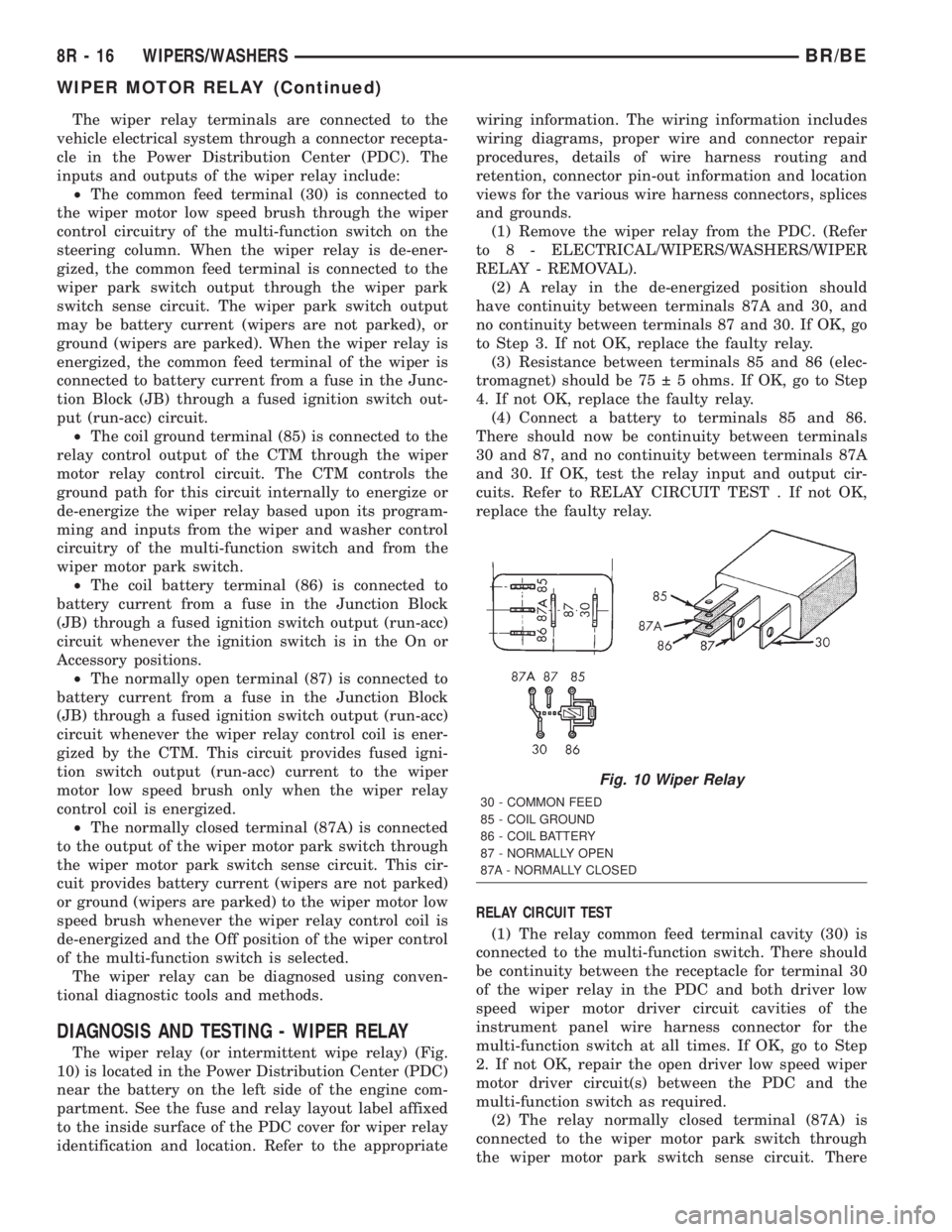
DIAGNOSIS AND TESTING - WIPER RELAY
The wiper relay (or intermittent wipe relay) (Fig.
10) is located in the Power Distribution Center (PDC)
near the battery on the left side of the engine com-
partment. See the fuse and relay layout label affixed
to the inside surface of the PDC cover for wiper relay
identification and location. Refer to the appropriatewiring information. The wiring information includes
wiring diagrams, proper wire and connector repair
procedures, details of wire harness routing and
retention, connector pin-out information and location
views for the various wire harness connectors, splices
and grounds.
(1) Remove the wiper relay from the PDC. (Refer
to 8 - ELECTRICAL/WIPERS/WASHERS/WIPER
RELAY - REMOVAL).
(2) A relay in the de-energized position should
have continuity between terminals 87A and 30, and
no continuity between terminals 87 and 30. If OK, go
to Step 3. If not OK, replace the faulty relay.
(3) Resistance between terminals 85 and 86 (elec-
tromagnet) should be 75 5 ohms. If OK, go to Step
4. If not OK, replace the faulty relay.
(4) Connect a battery to terminals 85 and 86.
There should now be continuity between terminals
30 and 87, and no continuity between terminals 87A
and 30. If OK, test the relay input and output cir-
cuits. Refer to RELAY CIRCUIT TEST . If not OK,
replace the faulty relay.
RELAY CIRCUIT TEST
(1) The relay common feed terminal cavity (30) is
connected to the multi-function switch. There should
be continuity between the receptacle for terminal 30
of the wiper relay in the PDC and both driver low
speed wiper motor driver circuit cavities of the
instrument panel wire harness connector for the
multi-function switch at all times. If OK, go to Step
2. If not OK, repair the open driver low speed wiper
motor driver circuit(s) between the PDC and the
multi-function switch as required.
(2) The relay normally closed terminal (87A) is
connected to the wiper motor park switch through
the wiper motor park switch sense circuit. There
Fig. 10 Wiper Relay
30 - COMMON FEED
85 - COIL GROUND
86 - COIL BATTERY
87 - NORMALLY OPEN
87A - NORMALLY CLOSED
8R - 16 WIPERS/WASHERSBR/BE
WIPER MOTOR RELAY (Continued)
Page 740 of 2889
should be continuity between the receptacle for ter-
minal 87A of the wiper relay in the PDC and the
wiper motor park switch sense circuit cavity of the
headlamp and dash wire harness connector for the
wiper motor at all times. If OK, go to Step 3. If not
OK, repair the open wiper motor park switch sense
circuit between the PDC and the wiper motor as
required.
(3) The relay normally open terminal (87) is con-
nected to a fused ignition switch output (run-acc)
fuse in the Junction Block (JB) through a fused igni-
tion switch output (run-acc) circuit. There should be
battery voltage at the receptacle for terminal 87 of
the wiper relay in the PDC whenever the ignition
switch is in the On or Accessory positions. If OK, go
to Step 4. If not OK, repair the open fused ignition
switch output (run-acc) circuit between the PDC and
the JB as required.
(4) The coil battery terminal (86) is connected to a
fused ignition switch output (run-acc) fuse in the JB
through a fused ignition switch output (run-acc) cir-
cuit. There should be battery voltage at the recepta-
cle for terminal 86 of the wiper relay in the PDC
whenever the ignition switch is in the On or Acces-
sory positions. If OK, go to Step 5. If not OK, repair
the open fused ignition switch output (run-acc) cir-
cuit between the PDC and the JB as required.
(5) The coil ground terminal (85) is connected to
the output of the Central Timer Module (CTM)
through the wiper motor relay control circuit. There
should be continuity between the receptacle for ter-
minal 85 of the wiper relay in the PDC and the wiper
motor relay control circuit cavity of the instrument
panel wire harness connector (Connector C1) for the
CTM at all times. If not OK, repair the open wiper
motor relay control circuit between the PDC and the
CTM as required.
REMOVAL
(1) Disconnect and isolate the battery negative
cable.(2) Remove the cover from the Power Distribution
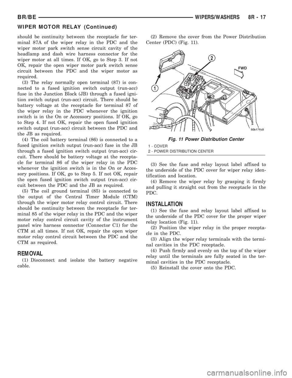
Center (PDC) (Fig. 11).
(3) See the fuse and relay layout label affixed to
the underside of the PDC cover for wiper relay iden-
tification and location.
(4) Remove the wiper relay by grasping it firmly
and pulling it straight out from the receptacle in the
PDC.
INSTALLATION
(1) See the fuse and relay layout label affixed to
the underside of the PDC cover for the proper wiper
relay location (Fig. 11).
(2) Position the wiper relay in the proper recepta-
cle in the PDC.
(3) Align the wiper relay terminals with the termi-
nal cavities in the PDC receptacle.
(4) Push firmly and evenly on the top of the wiper
relay until the terminals are fully seated in the ter-
minal cavities in the PDC receptacle.
(5) Reinstall the cover onto the PDC.
Fig. 11 Power Distribution Center
1 - COVER
2 - POWER DISTRIBUTION CENTER
BR/BEWIPERS/WASHERS 8R - 17
WIPER MOTOR RELAY (Continued)
Page 748 of 2889
TERMINOLOGY
This is a list of terms and definitions used in the
wiring diagrams.
LHD .................Left Hand Drive Vehicles
RHD................Right Hand Drive Vehicles
ATX . . Automatic Transmissions-Front Wheel Drive
MTX....Manual Transmissions-Front Wheel Drive
AT ....Automatic Transmissions-Rear Wheel Drive
MT .....Manual Transmissions-Rear Wheel Drive
SOHC...........Single Over Head Cam Engine
DOHC..........Double Over Head Cam Engine
Built-Up-Export........ Vehicles Built For Sale In
Markets Other Than North America
Except-Built-Up-Export . . Vehicles Built For Sale In
North America
WARNINGS - GENERAL
WARNINGSprovide information to prevent per-
sonal injury and vehicle damage. Below is a list of
general warnings that should be followed any time a
vehicle is being serviced.
WARNING:: ALWAYS WEAR SAFETY GLASSES FOR
EYE PROTECTION.
WARNING: USE SAFETY STANDS ANYTIME A PRO-
CEDURE REQUIRES BEING UNDER A VEHICLE.
WARNING: BE SURE THAT THE IGNITION SWITCH
ALWAYS IS IN THE OFF POSITION, UNLESS THE
PROCEDURE REQUIRES IT TO BE ON.
WARNING: SET THE PARKING BRAKE WHEN
WORKING ON ANY VEHICLE. AN AUTOMATIC
TRANSMISSION SHOULD BE IN PARK. A MANUAL
TRANSMISSION SHOULD BE IN NEUTRAL.
WARNING: OPERATE THE ENGINE ONLY IN A
WELL-VENTILATED AREA.
WARNING: KEEP AWAY FROM MOVING PARTS
WHEN THE ENGINE IS RUNNING, ESPECIALLY THE
FAN AND BELTS.
WARNING: TO PREVENT SERIOUS BURNS, AVOID
CONTACT WITH HOT PARTS SUCH AS THE RADIA-
TOR, EXHAUST MANIFOLD(S), TAIL PIPE, CATA-
LYTIC CONVERTER AND MUFFLER.WARNING: DO NOT ALLOW FLAME OR SPARKS
NEAR THE BATTERY. GASES ARE ALWAYS
PRESENT IN AND AROUND THE BATTERY.
WARNING: ALWAYS REMOVE RINGS, WATCHES,
LOOSE HANGING JEWELRY AND LOOSE CLOTH-
ING.
DIAGNOSIS AND TESTING - WIRING HARNESS
TROUBLESHOOTING TOOLS
When diagnosing a problem in an electrical circuit
there are several common tools necessary. These tools
are listed and explained below.
²Jumper Wire - This is a test wire used to con-
nect two points of a circuit. It can be used to bypass
an open in a circuit.
WARNING: NEVER USE A JUMPER WIRE ACROSS
A LOAD, SUCH AS A MOTOR, CONNECTED
BETWEEN A BATTERY FEED AND GROUND.
²Voltmeter - Used to check for voltage on a cir-
cuit. Always connect the black lead to a known good
ground and the red lead to the positive side of the
circuit.
CAUTION: Most of the electrical components used
in today's vehicles are Solid State. When checking
voltages in these circuits, use a meter with a 10 -
megohm or greater impedance rating.
²Ohmmeter - Used to check the resistance
between two points of a circuit. Low or no resistance
in a circuit means good continuity.
CAUTION: Most of the electrical components used
in today's vehicles are Solid State. When checking
resistance in these circuits use a meter with a 10 -
megohm or greater impedance rating. In addition,
make sure the power is disconnected from the cir-
cuit. Circuits that are powered up by the vehicle's
electrical system can cause damage to the equip-
ment and provide false readings.
²Probing Tools - These tools are used for probing
terminals in connectors (Fig. 4)Select the proper size
tool from Special Tool Package 6807, and insert it
into the terminal being tested. Use the other end of
the tool to insert the meter probe.
BR/BE8W-01 WIRING DIAGRAM INFORMATION 8W - 01 - 5
WIRING DIAGRAM INFORMATION (Continued)