Ground terminals DODGE RAM 2001 Service User Guide
[x] Cancel search | Manufacturer: DODGE, Model Year: 2001, Model line: RAM, Model: DODGE RAM 2001Pages: 2889, PDF Size: 68.07 MB
Page 540 of 2889
SPARK PLUG CABLE RESISTANCE
MINIMUM MAXIMUM
250 Ohms Per Inch 1000 Ohms Per Inch
3000 Ohms Per Foot 12,000 Ohms Per Foot
SPARK PLUGS
ENGINE PLUG TYPE ELECTRODE GAP
3.9L V-6 RC12LC4 1.01 mm (.040 in.)
5.2L/5.9L V-8 RC12LC4 1.01 mm (.040 in.)
8.0L V-10 QC9MC4 1.14 mm (.045 in.)
IGNITION COIL RESISTANCEÐ3.9L/5.2L/5.9L ENGINES
COIL MANUFACTURERPRIMARY RESISTANCE
21-27ÉC (70-80ÉF)SECONDARY RESISTANCE 21-27ÉC
(70-80ÉF)
Diamond 0.97 - 1.18 Ohms 11,300 - 15,300 Ohms
Toyodenso 0.95 - 1.20 Ohms 11,300 - 13,300 Ohms
IGNITION COIL RESISTANCEÐ8.0L V-10
ENGINE
Primary Resistance: 0.53-0.65 Ohms. Test across the
primary connector. Refer to text for test procedures.
Secondary Resistance: 10.9-14.7K Ohms. Test
across the individual coil towers. Refer to text for test
procedures.
IGNITION TIMING
Ignition timing is not adjustable on any engine.
AUTOMATIC SHUT DOWN
RELAY
DESCRIPTION - PCM OUTPUT
The 5±pin, 12±volt, Automatic Shutdown (ASD)
relay is located in the Power Distribution Center
(PDC). Refer to label on PDC cover for relay location.
OPERATION - PCM OUTPUT
The ASD relay supplies battery voltage (12+ volts)
to the fuel injectors and ignition coil(s). With certain
emissions packages it also supplies 12±volts to the
oxygen sensor heating elements.
The ground circuit for the coil within the ASD
relay is controlled by the Powertrain Control Module
(PCM). The PCM operates the ASD relay by switch-
ing its ground circuit on and off.The ASD relay will be shut±down, meaning the
12±volt power supply to the ASD relay will be de-ac-
tivated by the PCM if:
²the ignition key is left in the ON position. This
is if the engine has not been running for approxi-
mately 1.8 seconds.
²there is a crankshaft position sensor signal to
the PCM that is lower than pre-determined values.
OPERATION - ASD SENSE - PCM INPUT
A 12 volt signal at this input indicates to the PCM
that the ASD has been activated. The relay is used to
connect the oxygen sensor heater element, ignition
coil and fuel injectors to 12 volt + power supply.
This input is used only to sense that the ASD relay
is energized. If the Powertrain Control Module
(PCM) does not see 12 volts at this input when the
ASD should be activated, it will set a Diagnostic
Trouble Code (DTC).
DIAGNOSIS AND TESTING - ASD AND FUEL
PUMP RELAYS
The following description of operation and
tests apply only to the Automatic Shutdown
(ASD) and fuel pump relays. The terminals on the
bottom of each relay are numbered. Two different
types of relays may be used, (Fig. 1) or (Fig. 2).
²Terminal number 30 is connected to battery volt-
age. For both the ASD and fuel pump relays, termi-
nal 30 is connected to battery voltage at all times.
BR/BEIGNITION CONTROL 8I - 3
IGNITION CONTROL (Continued)
Page 541 of 2889
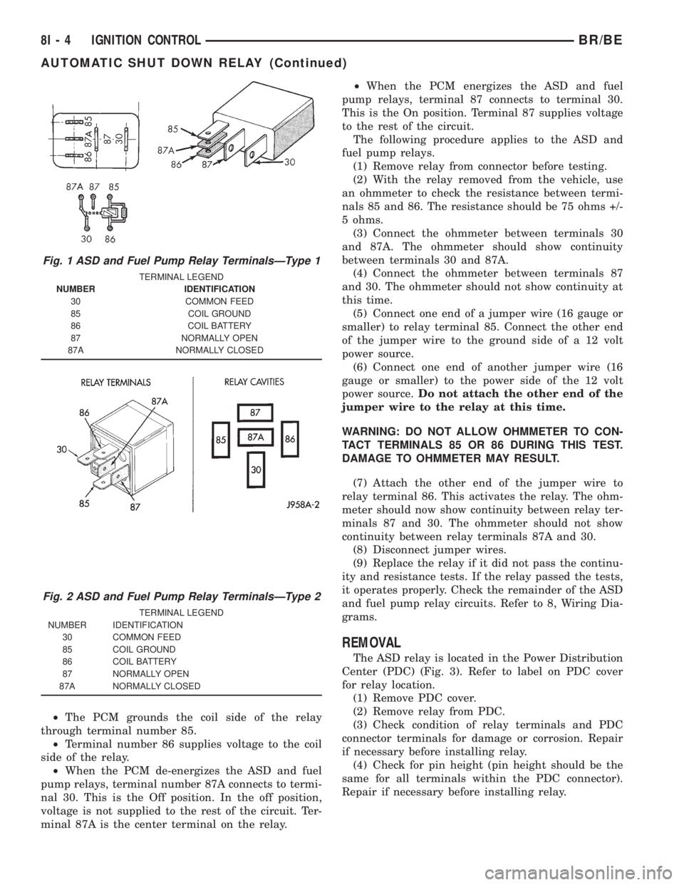
²The PCM grounds the coil side of the relay
through terminal number 85.
²Terminal number 86 supplies voltage to the coil
side of the relay.
²When the PCM de-energizes the ASD and fuel
pump relays, terminal number 87A connects to termi-
nal 30. This is the Off position. In the off position,
voltage is not supplied to the rest of the circuit. Ter-
minal 87A is the center terminal on the relay.²When the PCM energizes the ASD and fuel
pump relays, terminal 87 connects to terminal 30.
This is the On position. Terminal 87 supplies voltage
to the rest of the circuit.
The following procedure applies to the ASD and
fuel pump relays.
(1) Remove relay from connector before testing.
(2) With the relay removed from the vehicle, use
an ohmmeter to check the resistance between termi-
nals 85 and 86. The resistance should be 75 ohms +/-
5 ohms.
(3) Connect the ohmmeter between terminals 30
and 87A. The ohmmeter should show continuity
between terminals 30 and 87A.
(4) Connect the ohmmeter between terminals 87
and 30. The ohmmeter should not show continuity at
this time.
(5) Connect one end of a jumper wire (16 gauge or
smaller) to relay terminal 85. Connect the other end
of the jumper wire to the ground side of a 12 volt
power source.
(6) Connect one end of another jumper wire (16
gauge or smaller) to the power side of the 12 volt
power source.Do not attach the other end of the
jumper wire to the relay at this time.
WARNING: DO NOT ALLOW OHMMETER TO CON-
TACT TERMINALS 85 OR 86 DURING THIS TEST.
DAMAGE TO OHMMETER MAY RESULT.
(7) Attach the other end of the jumper wire to
relay terminal 86. This activates the relay. The ohm-
meter should now show continuity between relay ter-
minals 87 and 30. The ohmmeter should not show
continuity between relay terminals 87A and 30.
(8) Disconnect jumper wires.
(9) Replace the relay if it did not pass the continu-
ity and resistance tests. If the relay passed the tests,
it operates properly. Check the remainder of the ASD
and fuel pump relay circuits. Refer to 8, Wiring Dia-
grams.
REMOVAL
The ASD relay is located in the Power Distribution
Center (PDC) (Fig. 3). Refer to label on PDC cover
for relay location.
(1) Remove PDC cover.
(2) Remove relay from PDC.
(3) Check condition of relay terminals and PDC
connector terminals for damage or corrosion. Repair
if necessary before installing relay.
(4) Check for pin height (pin height should be the
same for all terminals within the PDC connector).
Repair if necessary before installing relay.
Fig. 1 ASD and Fuel Pump Relay TerminalsÐType 1
TERMINAL LEGEND
NUMBER IDENTIFICATION
30 COMMON FEED
85 COIL GROUND
86 COIL BATTERY
87 NORMALLY OPEN
87A NORMALLY CLOSED
Fig. 2 ASD and Fuel Pump Relay TerminalsÐType 2
TERMINAL LEGEND
NUMBER IDENTIFICATION
30 COMMON FEED
85 COIL GROUND
86 COIL BATTERY
87 NORMALLY OPEN
87A NORMALLY CLOSED
8I - 4 IGNITION CONTROLBR/BE
AUTOMATIC SHUT DOWN RELAY (Continued)
Page 551 of 2889
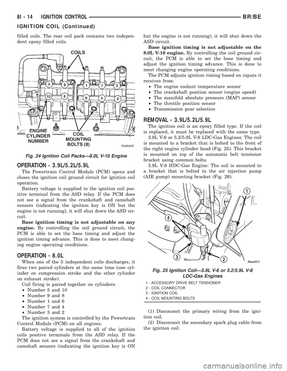
filled coils. The rear coil pack contains two indepen-
dent epoxy filled coils.
OPERATION - 3.9L/5.2L/5.9L
The Powertrain Control Module (PCM) opens and
closes the ignition coil ground circuit for ignition coil
operation.
Battery voltage is supplied to the ignition coil pos-
itive terminal from the ASD relay. If the PCM does
not see a signal from the crankshaft and camshaft
sensors (indicating the ignition key is ON but the
engine is not running), it will shut down the ASD cir-
cuit.
Base ignition timing is not adjustable on any
engine.By controlling the coil ground circuit, the
PCM is able to set the base timing and adjust the
ignition timing advance. This is done to meet chang-
ing engine operating conditions.
OPERATION - 8.0L
When one of the 5 independent coils discharges, it
fires two paired cylinders at the same time (one cyl-
inder on compression stroke and the other cylinder
on exhaust stroke).
Coil firing is paired together on cylinders:
²Number 5 and 10
²Number 9 and 8
²Number 1 and 6
²Number 7 and 4
²Number 3 and 2
The ignition system is controlled by the Powertrain
Control Module (PCM) on all engines.
Battery voltage is supplied to all of the ignition
coils positive terminals from the ASD relay. If the
PCM does not see a signal from the crankshaft and
camshaft sensors (indicating the ignition key is ONbut the engine is not running), it will shut down the
ASD circuit.
Base ignition timing is not adjustable on the
8.0L V-10 engine.By controlling the coil ground cir-
cuit, the PCM is able to set the base timing and
adjust the ignition timing advance. This is done to
meet changing engine operating conditions.
The PCM adjusts ignition timing based on inputs it
receives from:
²The engine coolant temperature sensor
²The crankshaft position sensor (engine speed)
²The manifold absolute pressure (MAP) sensor
²The throttle position sensor
²Transmission gear selection
REMOVAL - 3.9L/5.2L/5.9L
The ignition coil is an epoxy filled type. If the coil
is replaced, it must be replaced with the same type.
3.9L V-6 or 5.2/5.9L V-8 LDC-Gas Engines: The coil
is mounted to a bracket that is bolted to the front of
the right engine cylinder head (Fig. 25). This bracket
is mounted on top of the automatic belt tensioner
bracket using common bolts.
5.9L V-8 HDC-Gas Engine: The coil is mounted to
a bracket that is bolted to the air injection pump
(AIR pump) mounting bracket (Fig. 26).
(1) Disconnect the primary wiring from the igni-
tion coil.
(2) Disconnect the secondary spark plug cable from
the ignition coil.
Fig. 24 Ignition Coil PacksÐ8.0L V-10 Engine
Fig. 25 Ignition CoilÐ3.9L V-6 or 5.2/5.9L V-8
LDC-Gas Engines
1 - ACCESSORY DRIVE BELT TENSIONER
2 - COIL CONNECTOR
3 - IGNITION COIL
4 - COIL MOUNTING BOLTS
8I - 14 IGNITION CONTROLBR/BE
IGNITION COIL (Continued)
Page 556 of 2889
CLEANING
The plugs may be cleaned using commercially
available spark plug cleaning equipment. After clean-
ing, file center electrode flat with a small point file or
jewelers file before adjusting gap.
CAUTION: Never use a motorized wire wheel brush
to clean spark plugs. Metallic deposits will remain
on spark plug insulator and will cause plug misfire.
INSTALLATION
Special care should be taken when installing spark
plugs into the cylinder head spark plug wells. Be
sure the plugs do not drop into the plug wells as elec-
trodes can be damaged.
Always tighten spark plugs to the specified torque.
Over tightening can cause distortion resulting in a
change in the spark plug gap or a cracked porcelain
insulator.
When replacing the spark plug and ignition coil
cables, route the cables correctly and secure them in
the appropriate retainers. Failure to route the cables
properly can cause the radio to reproduce ignition
noise. It could cause cross ignition of the spark plugs
or short circuit the cables to ground.
(1) Start the spark plug into the cylinder head by
hand to avoid cross threading.
(2) Tighten spark plugs to 35-41 N´m (26-30 ft.
lbs.) torque.
(3) Install spark plug cables over spark plugs.
SPARK PLUG CABLE
DESCRIPTION
Spark plug cables are sometimes referred to as sec-
ondary ignition wires.
OPERATION
The spark plug cables transfer electrical current
from the ignition coil(s) and/or distributor, to individ-
ual spark plugs at each cylinder. The resistive spark
plug cables are of nonmetallic construction. The
cables provide suppression of radio frequency emis-
sions from the ignition system.
DIAGNOSIS AND TESTING - SPARK PLUG
CABLES
Cable routing is important on certain engines. To
prevent possible ignition crossfire, be sure the cables
are clipped into the plastic routing looms. Try to pre-
vent any one cable from contacting another. Before
removing cables, note their original location and
routing. Never allow one cable to be twisted around
another.
Check the spark plug cable connections for good
contact at the coil(s), distributor cap towers, and
spark plugs. Terminals should be fully seated. The
insulators should be in good condition and should fit
tightly on the coil, distributor and spark plugs. Spark
plug cables with insulators that are cracked or torn
must be replaced.
Clean high voltage ignition cables with a cloth
moistened with a non-flammable solvent. Wipe the
cables dry. Check for brittle or cracked insulation.
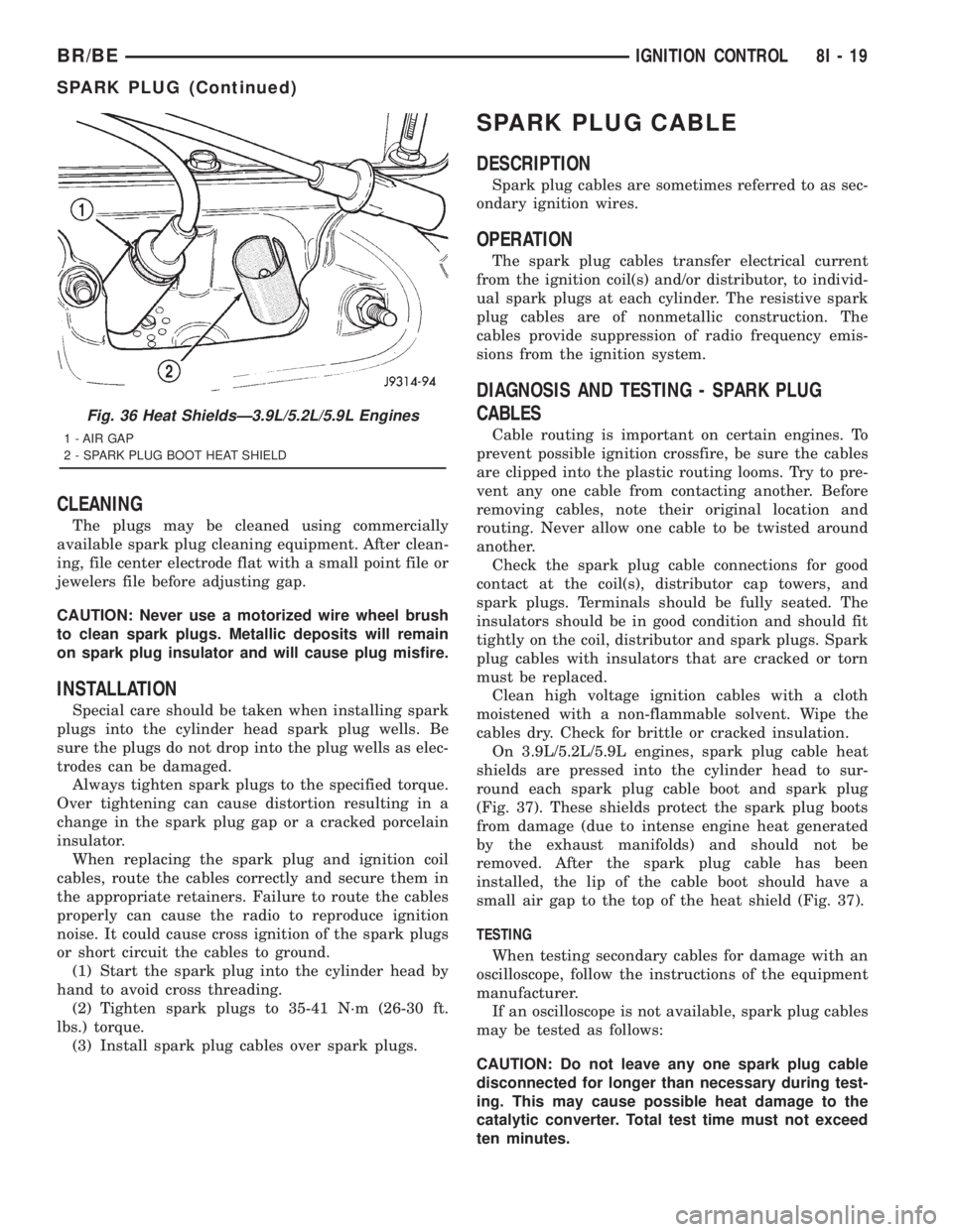
On 3.9L/5.2L/5.9L engines, spark plug cable heat
shields are pressed into the cylinder head to sur-
round each spark plug cable boot and spark plug
(Fig. 37). These shields protect the spark plug boots
from damage (due to intense engine heat generated
by the exhaust manifolds) and should not be
removed. After the spark plug cable has been
installed, the lip of the cable boot should have a
small air gap to the top of the heat shield (Fig. 37).
TESTING
When testing secondary cables for damage with an
oscilloscope, follow the instructions of the equipment
manufacturer.
If an oscilloscope is not available, spark plug cables
may be tested as follows:
CAUTION: Do not leave any one spark plug cable
disconnected for longer than necessary during test-
ing. This may cause possible heat damage to the
catalytic converter. Total test time must not exceed
ten minutes.
Fig. 36 Heat ShieldsÐ3.9L/5.2L/5.9L Engines
1 - AIR GAP
2 - SPARK PLUG BOOT HEAT SHIELD
BR/BEIGNITION CONTROL 8I - 19
SPARK PLUG (Continued)
Page 557 of 2889
With the engine running, remove spark plug cable
from spark plug (one at a time) and hold next to a
good engine ground. If the cable and spark plug are
in good condition, the engine rpm should drop and
the engine will run poorly. If engine rpm does not
drop, the cable and/or spark plug may not be operat-
ing properly and should be replaced. Also check
engine cylinder compression.
With the engine not running, connect one end of a
test probe to a good ground. Start the engine and run
the other end of the test probe along the entire
length of all spark plug cables. If cables are cracked
or punctured, there will be a noticeable spark jump
from the damaged area to the test probe. The cable
running from the ignition coil to the distributor cap
can be checked in the same manner. Cracked, dam-
aged or faulty cables should be replaced with resis-
tance type cable. This can be identified by the words
ELECTRONIC SUPPRESSION printed on the cable
jacket.
Use an ohmmeter to test for open circuits, exces-
sive resistance or loose terminals. If equipped,
remove the distributor cap from the distributor.Do
not remove cables from cap.Remove cable from
spark plug. Connect ohmmeter to spark plug termi-
nal end of cable and to corresponding electrode in
distributor cap. Resistance should be 250 to 1000
Ohms per inch of cable. If not, remove cable from dis-
tributor cap tower and connect ohmmeter to the ter-
minal ends of cable. If resistance is not within
specifications as found in the SPARK PLUG CABLE
RESISTANCE chart, replace the cable. Test all spark
plug cables in this manner.
SPARK PLUG CABLE RESISTANCE
MINIMUM MAXIMUM
250 Ohms Per Inch 1000 Ohms Per Inch
3000 Ohms Per Foot 12,000 Ohms Per Foot
To test ignition coil-to-distributor cap cable, do not
remove the cable from the cap. Connect ohmmeter to
rotor button (center contact) of distributor cap and
terminal at ignition coil end of cable. If resistance is
not within specifications as found in the Spark Plug
Cable Resistance chart, remove the cable from the
distributor cap. Connect the ohmmeter to the termi-
nal ends of the cable. If resistance is not within spec-
ifications as found in the Spark Plug Cable
Resistance chart, replace the cable. Inspect the igni-
tion coil tower for cracks, burns or corrosion.
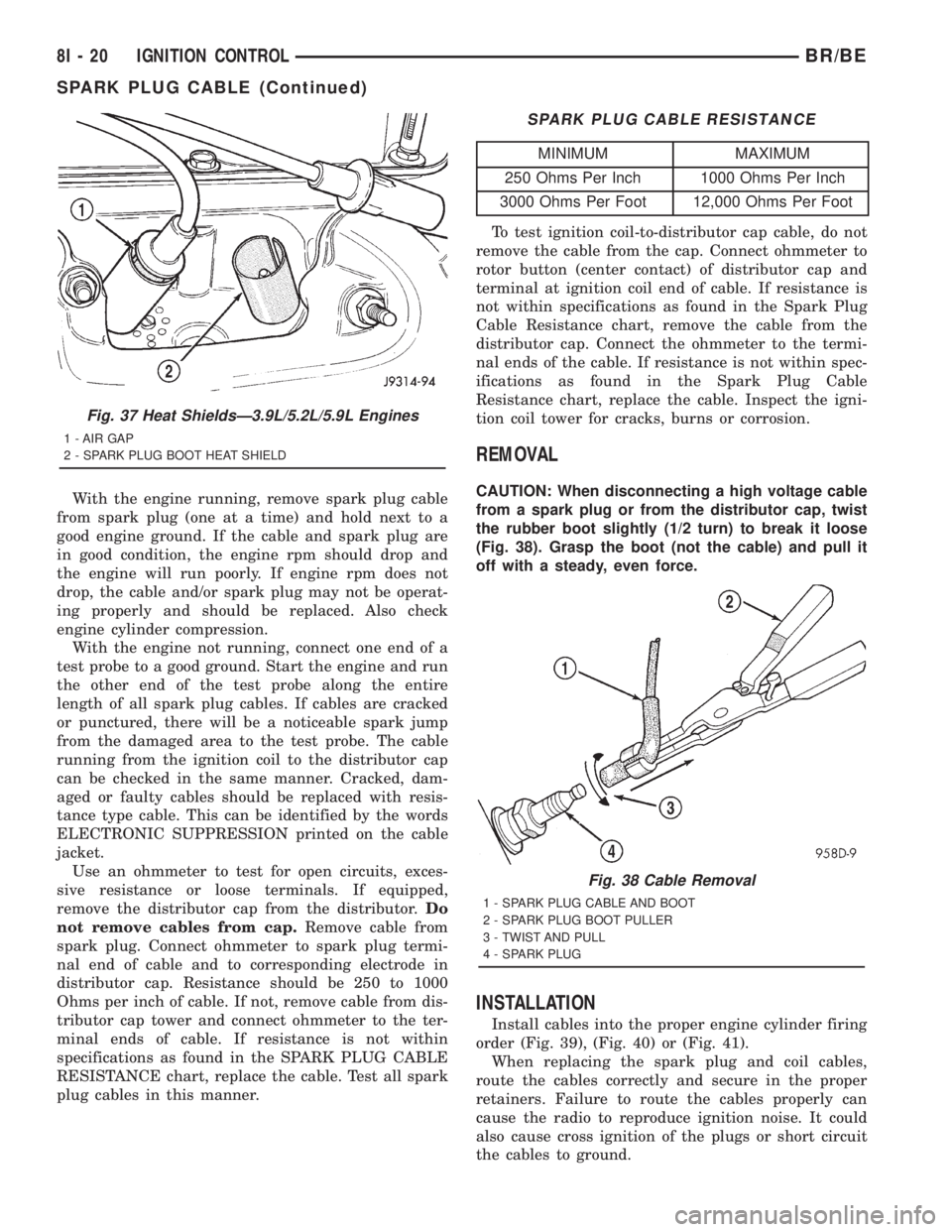
REMOVAL
CAUTION: When disconnecting a high voltage cable
from a spark plug or from the distributor cap, twist
the rubber boot slightly (1/2 turn) to break it loose
(Fig. 38). Grasp the boot (not the cable) and pull it
off with a steady, even force.
INSTALLATION
Install cables into the proper engine cylinder firing
order (Fig. 39), (Fig. 40) or (Fig. 41).
When replacing the spark plug and coil cables,
route the cables correctly and secure in the proper
retainers. Failure to route the cables properly can
cause the radio to reproduce ignition noise. It could
also cause cross ignition of the plugs or short circuit
the cables to ground.
Fig. 37 Heat ShieldsÐ3.9L/5.2L/5.9L Engines
1 - AIR GAP
2 - SPARK PLUG BOOT HEAT SHIELD
Fig. 38 Cable Removal
1 - SPARK PLUG CABLE AND BOOT
2 - SPARK PLUG BOOT PULLER
3 - TWIST AND PULL
4 - SPARK PLUG
8I - 20 IGNITION CONTROLBR/BE
SPARK PLUG CABLE (Continued)
Page 605 of 2889
will become high and the IC signals the PNP transis-
tor to de-energize the circuit. This cycling will con-
tinue until the right or left turn signal switch is
turned off.
A special design feature of the combination flasher
allows it to9sense9that a turn signal circuit or bulb
is not operating, and provide the driver an indication
of the condition by flashing the remaining bulbs in
the affected circuit at a higher rate (120 flashes-per-
minute or higher). Conventional flashers either con-
tinue flashing at their typical rate (heavy-duty type),
or discontinue flashing the affected circuit entirely
(standard-duty type). During turn signal operation,
the combination flasher IC compares normal battery
voltage input on pin 2 with the shunt resistor voltage
input on pin 7. If the IC9senses9that the voltage dif-
ference between pin 2 and pin 7 is different than the
pre-calibrated value of the IC, it will increase the
rate at which it signals the PNP transistor to ener-
gize the pin 1 output. Thus, the inoperative half (left
or right side) of the turn signal circuit will flash
faster.
Because of the active electronic elements within
the combination flasher, it cannot be tested with con-
ventional automotive electrical test equipment. If the
combination flasher is believed to be faulty, test the
turn signal system and hazard warning system. Then
replace the combination flasher with a known good
unit to confirm system operation. (Refer to 8 - ELEC-
TRICAL/LAMPS/LIGHTING - EXTERIOR/TURN
SIGNAL & HAZARD WARNING SYSTEM - DIAG-
NOSIS AND TESTING).
REMOVAL
WARNING: ON VEHICLES EQUIPPED WITH AIR-
BAGS, DISABLE THE AIRBAG SYSTEM BEFORE
ATTEMPTING ANY STEERING WHEEL, STEERING
COLUMN, OR INSTRUMENT PANEL COMPONENT
DIAGNOSIS OR SERVICE. DISCONNECT AND ISO-
LATE THE BATTERY NEGATIVE (GROUND) CABLE,
THEN WAIT TWO MINUTES FOR THE AIRBAG SYS-
TEM CAPACITOR TO DISCHARGE BEFORE PER-
FORMING FURTHER DIAGNOSIS OR SERVICE. THIS
IS THE ONLY SURE WAY TO DISABLE THE AIRBAG
SYSTEM. FAILURE TO TAKE THE PROPER PRE-
CAUTIONS COULD RESULT IN ACCIDENTAL AIR-
BAG DEPLOYMENT AND POSSIBLE PERSONAL
INJURY.
(1) Disconnect and isolate the battery negative
cable.
(2) Remove the fuse access panel by unsnapping it
from the left outboard end of the instrument panel.
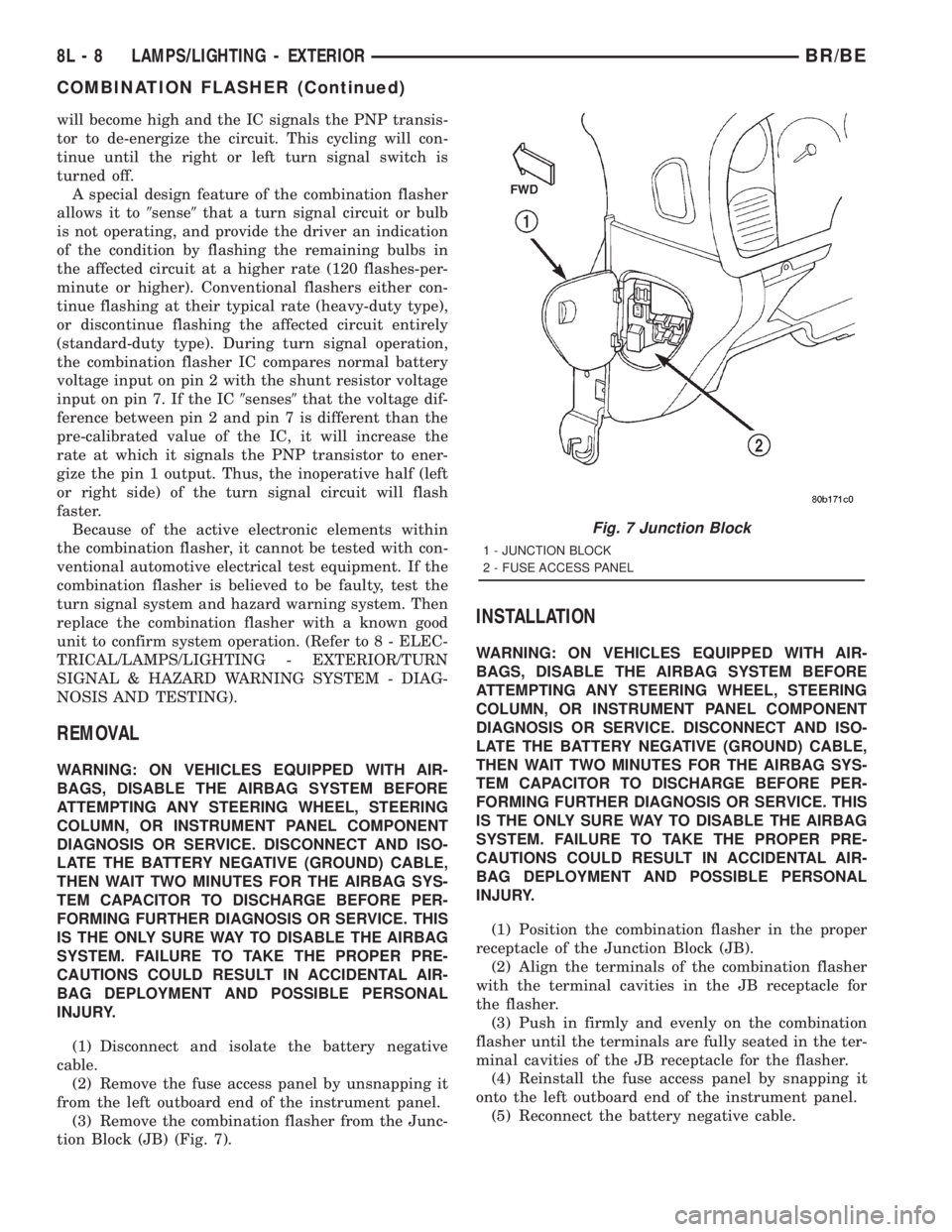
(3) Remove the combination flasher from the Junc-
tion Block (JB) (Fig. 7).
INSTALLATION
WARNING: ON VEHICLES EQUIPPED WITH AIR-
BAGS, DISABLE THE AIRBAG SYSTEM BEFORE
ATTEMPTING ANY STEERING WHEEL, STEERING
COLUMN, OR INSTRUMENT PANEL COMPONENT
DIAGNOSIS OR SERVICE. DISCONNECT AND ISO-
LATE THE BATTERY NEGATIVE (GROUND) CABLE,
THEN WAIT TWO MINUTES FOR THE AIRBAG SYS-
TEM CAPACITOR TO DISCHARGE BEFORE PER-
FORMING FURTHER DIAGNOSIS OR SERVICE. THIS
IS THE ONLY SURE WAY TO DISABLE THE AIRBAG
SYSTEM. FAILURE TO TAKE THE PROPER PRE-
CAUTIONS COULD RESULT IN ACCIDENTAL AIR-
BAG DEPLOYMENT AND POSSIBLE PERSONAL
INJURY.
(1) Position the combination flasher in the proper
receptacle of the Junction Block (JB).
(2) Align the terminals of the combination flasher
with the terminal cavities in the JB receptacle for
the flasher.
(3) Push in firmly and evenly on the combination
flasher until the terminals are fully seated in the ter-
minal cavities of the JB receptacle for the flasher.
(4) Reinstall the fuse access panel by snapping it
onto the left outboard end of the instrument panel.
(5) Reconnect the battery negative cable.
Fig. 7 Junction Block
1 - JUNCTION BLOCK
2 - FUSE ACCESS PANEL
8L - 8 LAMPS/LIGHTING - EXTERIORBR/BE
COMBINATION FLASHER (Continued)
Page 606 of 2889
DAYTIME RUNNING LAMP
MODULE
DESCRIPTION
The Daytime Running Lights (Headlamps) System
is installed on vehicles manufactured for sale in Can-
ada only. A separate module, mounted on the cowl,
controls the DRL.
OPERATION
The headlamps are illuminated when the ignition
switch is turned to the ON position. The DRL module
receives a vehicle-moving signal from the vehicle
speed sensor. This provides a constanthead-
lamps-oncondition as long as the vehicle is moving.
The lamps are illuminated at less than 50 percent of
normal intensity.
REMOVAL
(1) Disconnect and isolate the battery negative
cable.
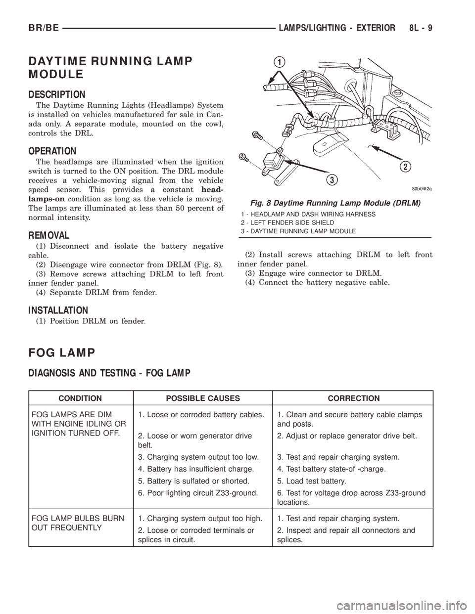
(2) Disengage wire connector from DRLM (Fig. 8).
(3) Remove screws attaching DRLM to left front
inner fender panel.
(4) Separate DRLM from fender.
INSTALLATION
(1) Position DRLM on fender.(2) Install screws attaching DRLM to left front
inner fender panel.
(3) Engage wire connector to DRLM.
(4) Connect the battery negative cable.
FOG LAMP
DIAGNOSIS AND TESTING - FOG LAMP
CONDITION POSSIBLE CAUSES CORRECTION
FOG LAMPS ARE DIM
WITH ENGINE IDLING OR
IGNITION TURNED OFF.1. Loose or corroded battery cables. 1. Clean and secure battery cable clamps
and posts.
2. Loose or worn generator drive
belt.2. Adjust or replace generator drive belt.
3. Charging system output too low. 3. Test and repair charging system.
4. Battery has insufficient charge. 4. Test battery state-of -charge.
5. Battery is sulfated or shorted. 5. Load test battery.
6. Poor lighting circuit Z33-ground. 6. Test for voltage drop across Z33-ground
locations.
FOG LAMP BULBS BURN
OUT FREQUENTLY1. Charging system output too high. 1. Test and repair charging system.
2. Loose or corroded terminals or
splices in circuit.2. Inspect and repair all connectors and
splices.
Fig. 8 Daytime Running Lamp Module (DRLM)
1 - HEADLAMP AND DASH WIRING HARNESS
2 - LEFT FENDER SIDE SHIELD
3 - DAYTIME RUNNING LAMP MODULE
BR/BELAMPS/LIGHTING - EXTERIOR 8L - 9
Page 607 of 2889
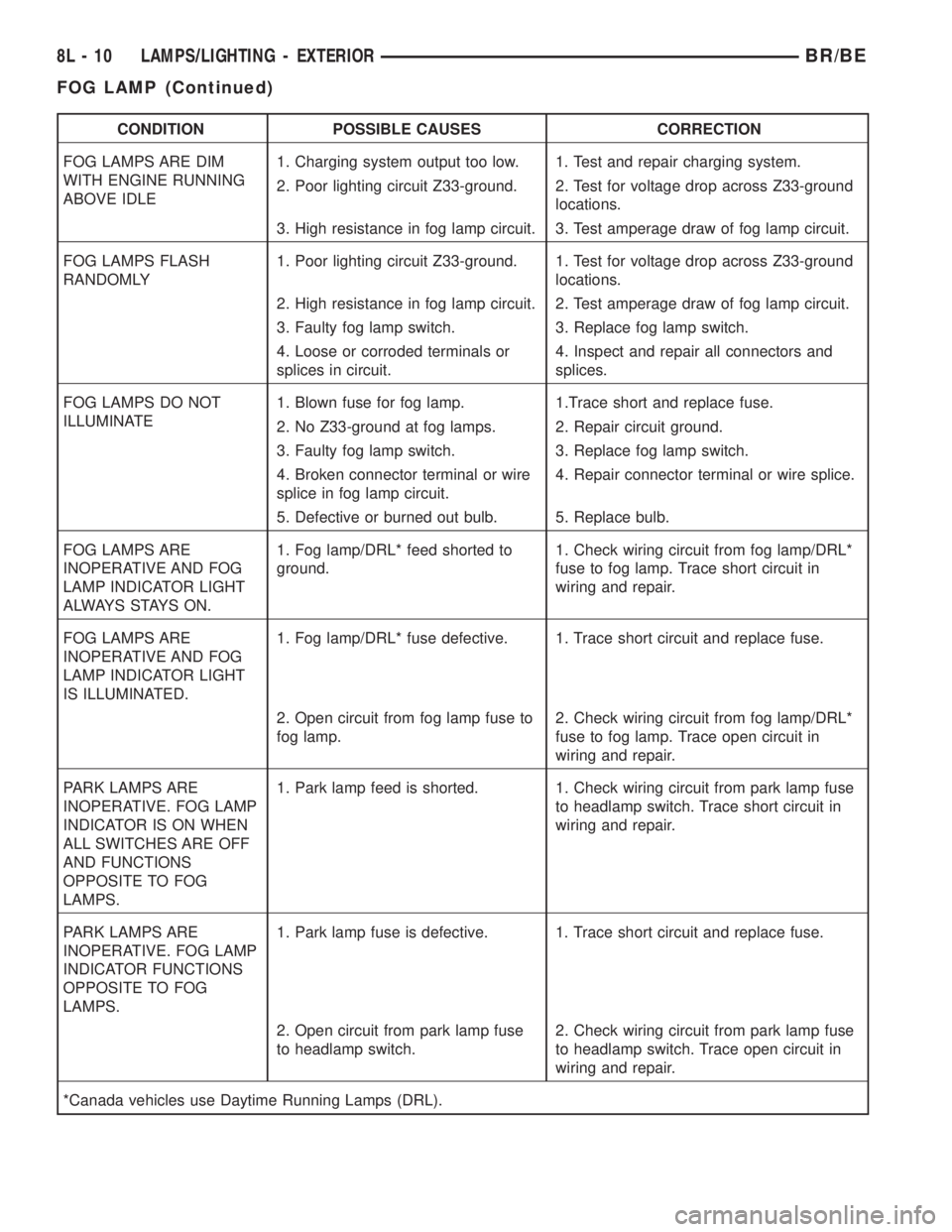
CONDITION POSSIBLE CAUSES CORRECTION
FOG LAMPS ARE DIM
WITH ENGINE RUNNING
ABOVE IDLE1. Charging system output too low. 1. Test and repair charging system.
2. Poor lighting circuit Z33-ground. 2. Test for voltage drop across Z33-ground
locations.
3. High resistance in fog lamp circuit. 3. Test amperage draw of fog lamp circuit.
FOG LAMPS FLASH
RANDOMLY1. Poor lighting circuit Z33-ground. 1. Test for voltage drop across Z33-ground
locations.
2. High resistance in fog lamp circuit. 2. Test amperage draw of fog lamp circuit.
3. Faulty fog lamp switch. 3. Replace fog lamp switch.
4. Loose or corroded terminals or
splices in circuit.4. Inspect and repair all connectors and
splices.
FOG LAMPS DO NOT
ILLUMINATE1. Blown fuse for fog lamp. 1.Trace short and replace fuse.
2. No Z33-ground at fog lamps. 2. Repair circuit ground.
3. Faulty fog lamp switch. 3. Replace fog lamp switch.
4. Broken connector terminal or wire
splice in fog lamp circuit.4. Repair connector terminal or wire splice.
5. Defective or burned out bulb. 5. Replace bulb.
FOG LAMPS ARE
INOPERATIVE AND FOG
LAMP INDICATOR LIGHT
ALWAYS STAYS ON.1. Fog lamp/DRL* feed shorted to
ground.1. Check wiring circuit from fog lamp/DRL*
fuse to fog lamp. Trace short circuit in
wiring and repair.
FOG LAMPS ARE
INOPERATIVE AND FOG
LAMP INDICATOR LIGHT
IS ILLUMINATED.1. Fog lamp/DRL* fuse defective. 1. Trace short circuit and replace fuse.
2. Open circuit from fog lamp fuse to
fog lamp.2. Check wiring circuit from fog lamp/DRL*
fuse to fog lamp. Trace open circuit in
wiring and repair.
PARK LAMPS ARE
INOPERATIVE. FOG LAMP
INDICATOR IS ON WHEN
ALL SWITCHES ARE OFF
AND FUNCTIONS
OPPOSITE TO FOG
LAMPS.1. Park lamp feed is shorted. 1. Check wiring circuit from park lamp fuse
to headlamp switch. Trace short circuit in
wiring and repair.
PARK LAMPS ARE
INOPERATIVE. FOG LAMP
INDICATOR FUNCTIONS
OPPOSITE TO FOG
LAMPS.1. Park lamp fuse is defective. 1. Trace short circuit and replace fuse.
2. Open circuit from park lamp fuse
to headlamp switch.2. Check wiring circuit from park lamp fuse
to headlamp switch. Trace open circuit in
wiring and repair.
*Canada vehicles use Daytime Running Lamps (DRL).
8L - 10 LAMPS/LIGHTING - EXTERIORBR/BE
FOG LAMP (Continued)
Page 611 of 2889
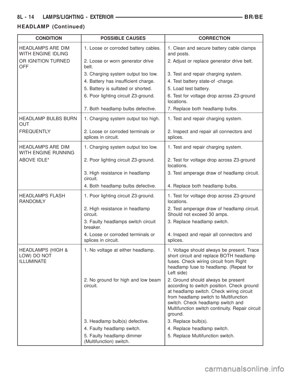
CONDITION POSSIBLE CAUSES CORRECTION
HEADLAMPS ARE DIM
WITH ENGINE IDLING1. Loose or corroded battery cables. 1. Clean and secure battery cable clamps
and posts.
OR IGNITION TURNED
OFF2. Loose or worn generator drive
belt.2. Adjust or replace generator drive belt.
3. Charging system output too low. 3. Test and repair charging system.
4. Battery has insufficient charge. 4. Test battery state-of -charge.
5. Battery is sulfated or shorted. 5. Load test battery.
6. Poor lighting circuit Z3-ground. 6. Test for voltage drop across Z3-ground
locations.
7. Both headlamp bulbs defective. 7. Replace both headlamp bulbs.
HEADLAMP BULBS BURN
OUT1. Charging system output too high. 1. Test and repair charging system.
FREQUENTLY 2. Loose or corroded terminals or
splices in circuit.2. Inspect and repair all connectors and
splices.
HEADLAMPS ARE DIM
WITH ENGINE RUNNING1. Charging system output too low. 1. Test and repair charging system.
ABOVE IDLE* 2. Poor lighting circuit Z3-ground. 2. Test for voltage drop across Z3-ground
locations.
3. High resistance in headlamp
circuit.3. Test amperage draw of headlamp circuit.
4. Both headlamp bulbs defective. 4. Replace both headlamp bulbs.
HEADLAMPS FLASH
RANDOMLY1. Poor lighting circuit Z3-ground. 1. Test for voltage drop across Z3-ground
locations.
2. High resistance in headlamp
circuit.2. Test amperage draw of headlamp circuit.
Should not exceed 30 amps.
3. Faulty headlamps switch circuit
breaker.3. Replace headlamp switch.
4. Loose or corroded terminals or
splices in circuit.4. Inspect and repair all connectors and
splices.
HEADLAMPS (HIGH &
LOW) DO NOT
ILLUMINATE1. No voltage at either headlamp. 1. Voltage should always be present. Trace
short circuit and replace BOTH headlamp
fuses. Check wiring circuit from Right
headlamp fuse to headlamp. (Repeat for
Left side)
2. No ground for high and low beam
circuit.2. Ground should always be present
according to switch position. Check ground
at headlamp switch. Check wiring circuit
from headlamp switch to Multifunction
switch. Check headlamp switch and
Multifunction switch continuity. Repair circuit
ground.
3. Headlamp bulb(s) defective. 3. Replace bulb(s).
4. Faulty headlamp switch. 4. Replace headlamp switch.
5. Faulty headlamp dimmer
(Multifunction) switch.5. Replace Multifunction switch.
8L - 14 LAMPS/LIGHTING - EXTERIORBR/BE
HEADLAMP (Continued)
Page 613 of 2889
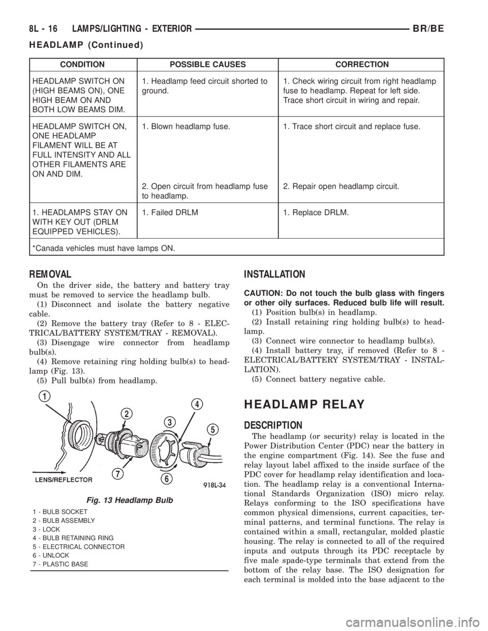
CONDITION POSSIBLE CAUSES CORRECTION
HEADLAMP SWITCH ON
(HIGH BEAMS ON), ONE
HIGH BEAM ON AND
BOTH LOW BEAMS DIM.1. Headlamp feed circuit shorted to
ground.1. Check wiring circuit from right headlamp
fuse to headlamp. Repeat for left side.
Trace short circuit in wiring and repair.
HEADLAMP SWITCH ON,
ONE HEADLAMP
FILAMENT WILL BE AT
FULL INTENSITY AND ALL
OTHER FILAMENTS ARE
ON AND DIM.1. Blown headlamp fuse. 1. Trace short circuit and replace fuse.
2. Open circuit from headlamp fuse
to headlamp.2. Repair open headlamp circuit.
1. HEADLAMPS STAY ON
WITH KEY OUT (DRLM
EQUIPPED VEHICLES).1. Failed DRLM 1. Replace DRLM.
*Canada vehicles must have lamps ON.
REMOVAL
On the driver side, the battery and battery tray
must be removed to service the headlamp bulb.
(1) Disconnect and isolate the battery negative
cable.
(2) Remove the battery tray (Refer to 8 - ELEC-
TRICAL/BATTERY SYSTEM/TRAY - REMOVAL).
(3) Disengage wire connector from headlamp
bulb(s).
(4) Remove retaining ring holding bulb(s) to head-
lamp (Fig. 13).
(5) Pull bulb(s) from headlamp.
INSTALLATION
CAUTION: Do not touch the bulb glass with fingers
or other oily surfaces. Reduced bulb life will result.
(1) Position bulb(s) in headlamp.
(2) Install retaining ring holding bulb(s) to head-
lamp.
(3) Connect wire connector to headlamp bulb(s).
(4) Install battery tray, if removed (Refer to 8 -
ELECTRICAL/BATTERY SYSTEM/TRAY - INSTAL-
LATION).
(5) Connect battery negative cable.
HEADLAMP RELAY
DESCRIPTION
The headlamp (or security) relay is located in the
Power Distribution Center (PDC) near the battery in
the engine compartment (Fig. 14). See the fuse and
relay layout label affixed to the inside surface of the
PDC cover for headlamp relay identification and loca-
tion. The headlamp relay is a conventional Interna-
tional Standards Organization (ISO) micro relay.
Relays conforming to the ISO specifications have
common physical dimensions, current capacities, ter-
minal patterns, and terminal functions. The relay is
contained within a small, rectangular, molded plastic
housing. The relay is connected to all of the required
inputs and outputs through its PDC receptacle by
five male spade-type terminals that extend from the
bottom of the relay base. The ISO designation for
each terminal is molded into the base adjacent to the
Fig. 13 Headlamp Bulb
1 - BULB SOCKET
2 - BULB ASSEMBLY
3 - LOCK
4 - BULB RETAINING RING
5 - ELECTRICAL CONNECTOR
6 - UNLOCK
7 - PLASTIC BASE
8L - 16 LAMPS/LIGHTING - EXTERIORBR/BE
HEADLAMP (Continued)