interior DODGE RAM 2001 Service Manual PDF
[x] Cancel search | Manufacturer: DODGE, Model Year: 2001, Model line: RAM, Model: DODGE RAM 2001Pages: 2889, PDF Size: 68.07 MB
Page 2574 of 2889
BODY
TABLE OF CONTENTS
page page
BODY
DESCRIPTION............................1
WARNING...............................1
DIAGNOSIS AND TESTING..................2
WATER LEAKS..........................2
WIND NOISE...........................3
SPECIFICATIONS.........................4
DECKLID/HATCH/LIFTGATE/TAILGATE........62
DOOR - FRONT..........................67DOOR - CARGO.........................77
EXTERIOR..............................86
HOOD.................................99
INSTRUMENT PANEL SYSTEM.............104
INTERIOR.............................118
PAINT................................129
SEATS................................131
STATIONARY GLASS.....................145
WEATHERSTRIP/SEALS..................152
BODY
DESCRIPTION ± PUSH-IN FASTENERS
DaimlerChrysler Corporation uses many different
types of push-in fasteners to secure the interior and
exterior trim to the body. Most of these fasteners can
be reused to assemble the trim during various repair
procedures. At times, a push-in fastener cannot be
removed without damaging the fastener or the com-
ponent it is holding. If it is not possible to remove a
fastener without damaging a component or body, cut
or break the fastener and use a new one when
installing the component. Never pry or pound on a
plastic or pressed-board trim component. Using a
suitable fork-type prying device, pry the fastener
from the retaining hole behind the component being
removed. When installing, verify fastener alignment
with the retaining hole by hand. Push directly on or
over the fastener until it seats. Apply a low-force pull
to the panel to verify that it is secure.
When it is necessary to remove components to ser-
vice another, it should not be necessary to apply
excessive force or bend a component to remove it.
Before damaging a trim component, verify hidden
fasteners or captured edges holding the component in
place.
DESCRIPTION ± LOCK CYLINDERS
Ignition, door, deck lid, and rear hatch lock cylin-
ders are all codable to the key. Lock barrels, tum-
blers, and tumbler springs are available to allow the
technician to change replacement locks cylinders to
match the customer's original key set. See the appro-
priate section in this manual for lock cylinder
removal. See the Moparž catalogue for part numbers
and lock coding procedures.
SAFETY PRECAUTIONS AND WARNINGS
WARNING: USE A OSHA APPROVED BREATHING
FILTER WHEN SPRAYING PAINT OR SOLVENTS IN
A CONFINED AREA. PERSONAL INJURY CAN
RESULT.
AVOID PROLONGED SKIN CONTACT WITH PETRO-
LEUM OR ALCOHOL ± BASED CLEANING SOL-
VENTS. PERSONAL INJURY CAN RESULT.
DO NOT STAND UNDER A HOISTED VEHICLE THAT
IS NOT PROPERLY SUPPORTED ON SAFETY
STANDS. PERSONAL INJURY CAN RESULT.
CAUTION: When holes must be drilled or punched
in an inner body panel, verify depth of space to the
outer body panel, electrical wiring, or other compo-
nents. Damage to vehicle can result.
Do not weld exterior panels unless combustible
material on the interior of vehicle is removed from
the repair area. Fire or hazardous conditions, can
result.
Always have a fire extinguisher ready for use when
welding.
Disconnect the negative (-) cable clamp from the
battery when servicing electrical components that
are live when the ignition is OFF. Damage to electri-
cal system can result.
Do not use abrasive chemicals or compounds on
painted surfaces. Damage to finish can result.
Do not use harsh alkaline based cleaning solvents
on painted or upholstered surfaces. Damage to fin-
ish or color can result.
Do not hammer or pound on plastic trim panel
when servicing interior trim. Plastic panels can
break.
BR/BEBODY 23 - 1
Page 2575 of 2889
DIAGNOSIS AND TESTING ± WATER LEAKS
Water leaks can be caused by poor sealing,
improper body component alignment, body seam
porosity, missing plugs, or blocked drain holes. Cen-
trifugal and gravitational force can cause water to
drip from a location away from the actual leak point,
making leak detection difficult. All body sealing
points should be water tight in normal wet-driving
conditions. Water flowing downward from the front of
the vehicle should not enter the passenger or luggage
compartment. Moving sealing surfaces will not
always seal water tight under all conditions. At
times, side glass or door seals will allow water to
enter the passenger compartment during high pres-
sure washing or hard driving rain (severe) condi-
tions. Overcompensating on door or glass
adjustments to stop a water leak that occurs under
severe conditions can cause premature seal wear and
excessive closing or latching effort. After completing
a repair, water test vehicle to verify leak has stopped
before returning vehicle to use.
VISUAL INSPECTION BEFORE WATER LEAK TESTS
Verify that floor and body plugs are in place, body
drains are clear, and body components are properly
aligned and sealed. If component alignment or seal-
ing is necessary, refer to the appropriate section of
this group for proper procedures.
WATER LEAK TESTS
WARNING: DO NOT USE ELECTRIC SHOP LIGHTS
OR TOOLS IN WATER TEST AREA. PERSONAL
INJURY CAN RESULT.
When the conditions causing a water leak have
been determined, simulate the conditions as closely
as possible.
²If a leak occurs with the vehicle parked in a
steady light rain, flood the leak area with an open-
ended garden hose.
²If a leak occurs while driving at highway speeds
in a steady rain, test the leak area with a reasonable
velocity stream or fan spray of water. Direct the
spray in a direction comparable to actual conditions.
²If a leak occurs when the vehicle is parked on an
incline, hoist the end or side of the vehicle to simu-
late this condition. This method can be used when
the leak occurs when the vehicle accelerates, stops or
turns. If the leak occurs on acceleration, hoist the
front of the vehicle. If the leak occurs when braking,
hoist the back of the vehicle. If the leak occurs on left
turns, hoist the left side of the vehicle. If the leak
occurs on right turns, hoist the right side of the vehi-
cle. For hoisting recommendations refer to Group 0,
Lubrication and Maintenance, General Information
section.
WATER LEAK DETECTION
To detect a water leak point-of-entry, do a water
test and watch for water tracks or droplets forming
on the inside of the vehicle. If necessary, remove inte-
rior trim covers or panels to gain visual access to the
leak area. If the hose cannot be positioned without
being held, have someone help do the water test.
Some water leaks must be tested for a considerable
length of time to become apparent. When a leak
appears, find the highest point of the water track or
drop. The highest point usually will show the point of
entry. After leak point has been found, repair the
leak and water test to verify that the leak has
stopped.
Locating the entry point of water that is leaking
into a cavity between panels can be difficult. The
trapped water may splash or run from the cavity,
often at a distance from the entry point. Most water
leaks of this type become apparent after accelerating,
stopping, turning, or when on an incline.
MIRROR INSPECTION METHOD
When a leak point area is visually obstructed, use
a suitable mirror to gain visual access. A mirror can
also be used to deflect light to a limited-access area
to assist in locating a leak point.
BRIGHT LIGHT LEAK TEST METHOD
Some water leaks in the luggage compartment can
be detected without water testing. Position the vehi-
cle in a brightly lit area. From inside the darkened
luggage compartment inspect around seals and body
seams. If necessary, have a helper direct a drop light
over the suspected leak areas around the luggage
compartment. If light is visible through a normally
sealed location, water could enter through the open-
ing.
PRESSURIZED LEAK TEST METHOD
When a water leak into the passenger compart-
ment cannot be detected by water testing, pressurize
the passenger compartment and soap test exterior of
the vehicle. To pressurize the passenger compart-
ment, close all doors and windows, start engine, and
set heater control to high blower in HEAT position. If
engine can not be started, connect a charger to the
battery to ensure adequate voltage to the blower.
With interior pressurized, apply dish detergent solu-
tion to suspected leak area on the exterior of the
vehicle. Apply detergent solution with spray device or
soft bristle brush. If soap bubbles occur at a body
seam, joint, seal or gasket, the leak entry point could
be at that location.
23 - 2 BODYBR/BE
BODY (Continued)
Page 2641 of 2889
(15) Install outer belt weatherstrip (Refer to 23 -
BODY/WEATHERSTRIP/SEALS/FDR OUTER BELT
WEATHERSTRIP - INSTALLATION).
(16) Install glass run weatherstrip (Refer to 23 -
BODY/WEATHERSTRIP/SEALS/FDR GLASS RUN
WEATHERSTRIP - INSTALLATION).
DOOR
REMOVAL
(1) Remove cowl trim panel (Refer to 23 - BODY/
INTERIOR/COWL TRIM COVER - REMOVAL).
(2) Disengage door wire harness connector of
instrument panel harness and push door harness
through access hole in pillar.
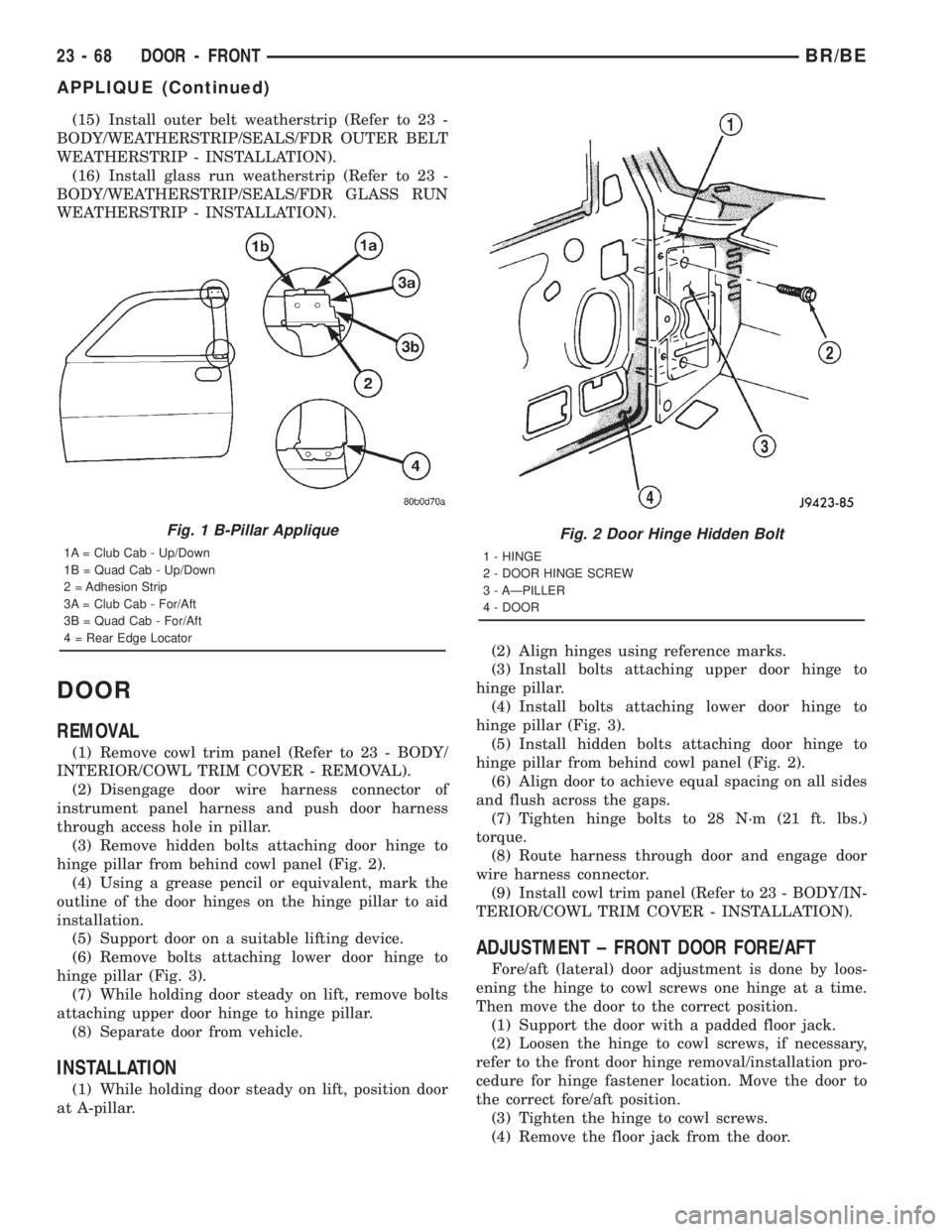
(3) Remove hidden bolts attaching door hinge to
hinge pillar from behind cowl panel (Fig. 2).
(4) Using a grease pencil or equivalent, mark the
outline of the door hinges on the hinge pillar to aid
installation.
(5) Support door on a suitable lifting device.
(6) Remove bolts attaching lower door hinge to
hinge pillar (Fig. 3).
(7) While holding door steady on lift, remove bolts
attaching upper door hinge to hinge pillar.
(8) Separate door from vehicle.
INSTALLATION
(1) While holding door steady on lift, position door
at A-pillar.(2) Align hinges using reference marks.
(3) Install bolts attaching upper door hinge to
hinge pillar.
(4) Install bolts attaching lower door hinge to
hinge pillar (Fig. 3).
(5) Install hidden bolts attaching door hinge to
hinge pillar from behind cowl panel (Fig. 2).
(6) Align door to achieve equal spacing on all sides
and flush across the gaps.
(7) Tighten hinge bolts to 28 N´m (21 ft. lbs.)
torque.
(8) Route harness through door and engage door
wire harness connector.
(9) Install cowl trim panel (Refer to 23 - BODY/IN-
TERIOR/COWL TRIM COVER - INSTALLATION).
ADJUSTMENT ± FRONT DOOR FORE/AFT
Fore/aft (lateral) door adjustment is done by loos-
ening the hinge to cowl screws one hinge at a time.
Then move the door to the correct position.
(1) Support the door with a padded floor jack.
(2) Loosen the hinge to cowl screws, if necessary,
refer to the front door hinge removal/installation pro-
cedure for hinge fastener location. Move the door to
the correct fore/aft position.
(3) Tighten the hinge to cowl screws.
(4) Remove the floor jack from the door.
Fig. 1 B-Pillar Applique
1A = Club Cab - Up/Down
1B = Quad Cab - Up/Down
2 = Adhesion Strip
3A = Club Cab - For/Aft
3B = Quad Cab - For/Aft
4 = Rear Edge Locator
Fig. 2 Door Hinge Hidden Bolt
1 - HINGE
2 - DOOR HINGE SCREW
3 - AÐPILLER
4 - DOOR
23 - 68 DOOR - FRONTBR/BE
APPLIQUE (Continued)
Page 2643 of 2889
EXTERIOR HANDLE
REMOVAL
(1) Remove the waterdam (Refer to 23 - BODY/
DOOR - FRONT/WATERDAM - REMOVAL).
(2) Raise the window to the closed position.
(3) Remove fastener access plug from door end
panel.
(4) Disengage clips holding latch and lock rods to
door latch.
(5) Separate latch and lock rods from door latch.
(6) Remove nuts attaching outside door handle to
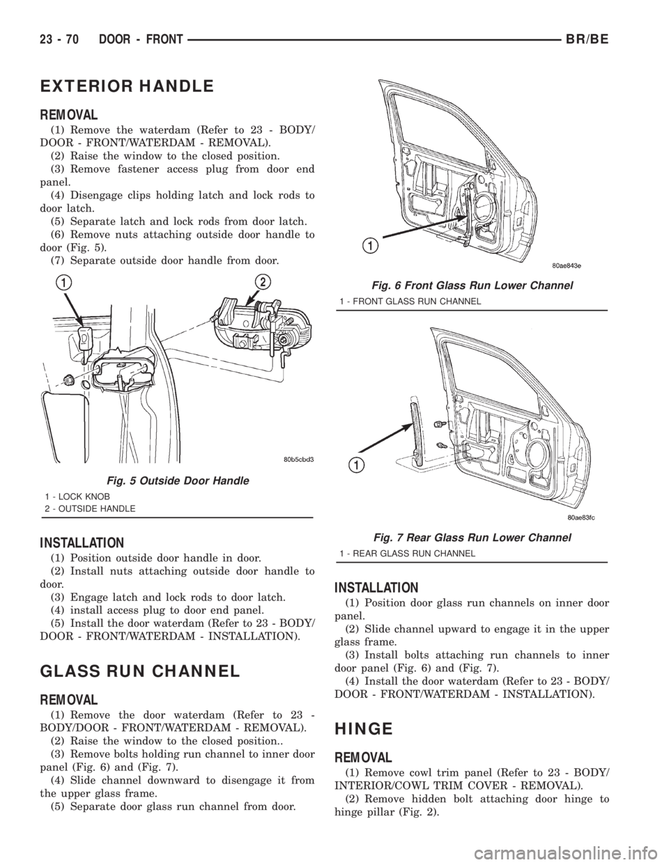
door (Fig. 5).
(7) Separate outside door handle from door.
INSTALLATION
(1) Position outside door handle in door.
(2) Install nuts attaching outside door handle to
door.
(3) Engage latch and lock rods to door latch.
(4) install access plug to door end panel.
(5) Install the door waterdam (Refer to 23 - BODY/
DOOR - FRONT/WATERDAM - INSTALLATION).
GLASS RUN CHANNEL
REMOVAL
(1) Remove the door waterdam (Refer to 23 -
BODY/DOOR - FRONT/WATERDAM - REMOVAL).
(2) Raise the window to the closed position..
(3) Remove bolts holding run channel to inner door
panel (Fig. 6) and (Fig. 7).
(4) Slide channel downward to disengage it from
the upper glass frame.
(5) Separate door glass run channel from door.
INSTALLATION
(1) Position door glass run channels on inner door
panel.
(2) Slide channel upward to engage it in the upper
glass frame.
(3) Install bolts attaching run channels to inner
door panel (Fig. 6) and (Fig. 7).
(4) Install the door waterdam (Refer to 23 - BODY/
DOOR - FRONT/WATERDAM - INSTALLATION).
HINGE
REMOVAL
(1) Remove cowl trim panel (Refer to 23 - BODY/
INTERIOR/COWL TRIM COVER - REMOVAL).
(2) Remove hidden bolt attaching door hinge to
hinge pillar (Fig. 2).
Fig. 5 Outside Door Handle
1 - LOCK KNOB
2 - OUTSIDE HANDLE
Fig. 6 Front Glass Run Lower Channel
1 - FRONT GLASS RUN CHANNEL
Fig. 7 Rear Glass Run Lower Channel
1 - REAR GLASS RUN CHANNEL
23 - 70 DOOR - FRONTBR/BE
Page 2652 of 2889
(5) If necessary, loosen the bolts attaching the
lower striker and move striker to the correct position.
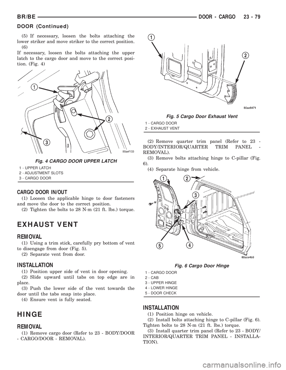
(6)
If necessary, loosen the bolts attaching the upper
latch to the cargo door and move to the correct posi-
tion. (Fig. 4)
CARGO DOOR IN/OUT
(1) Loosen the applicable hinge to door fasteners
and move the door to the correct position.
(2) Tighten the bolts to 28 N´m (21 ft. lbs.) torque.
EXHAUST VENT
REMOVAL
(1) Using a trim stick, carefully pry bottom of vent
to disengage from door (Fig. 5).
(2) Separate vent from door.
INSTALLATION
(1) Position upper side of vent in door opening.
(2) Slide upward until tabs on top edge are in
place.
(3) Push the lower side of the vent towards the
door until the tabs snap into place.
(4) Ensure vent is fully seated.
HINGE
REMOVAL
(1) Remove cargo door (Refer to 23 - BODY/DOOR
- CARGO/DOOR - REMOVAL).(2) Remove quarter trim panel (Refer to 23 -
BODY/INTERIOR/QUARTER TRIM PANEL -
REMOVAL).
(3) Remove bolts attaching hinge to C-pillar (Fig.
6).
(4) Separate hinge from vehicle.
INSTALLATION
(1) Position hinge on vehicle.
(2) Install bolts attaching hinge to C-pillar (Fig. 6).
Tighten bolts to 28 N´m (21 ft. lbs.) torque.
(3) Install quarter trim panel (Refer to 23 - BODY/
INTERIOR/QUARTER TRIM PANEL - INSTALLA-
TION).
Fig. 4 CARGO DOOR UPPER LATCH
1 - UPPER LATCH
2 - ADJUSTMENT SLOTS
3 - CARGO DOOR
Fig. 5 Cargo Door Exhaust Vent
1 - CARGO DOOR
2 - EXHAUST VENT
Fig. 6 Cargo Door Hinge
1 - CARGO DOOR
2 - CAB
3 - UPPER HINGE
4 - LOWER HINGE
5 - DOOR CHECK
BR/BEDOOR - CARGO 23 - 79
DOOR (Continued)
Page 2679 of 2889
REMOVAL
WARNING: ON VEHICLES EQUIPPED WITH AIR-
BAGS, DISABLE THE AIRBAG SYSTEM BEFORE
ATTEMPTING ANY STEERING WHEEL, STEERING
COLUMN, OR INSTRUMENT PANEL COMPONENT
DIAGNOSIS OR SERVICE. DISCONNECT AND ISO-
LATE THE BATTERY NEGATIVE (GROUND) CABLE,
THEN WAIT TWO MINUTES FOR THE AIRBAG SYS-
TEM CAPACITOR TO DISCHARGE BEFORE PER-
FORMING FURTHER DIAGNOSIS OR SERVICE. THIS
IS THE ONLY SURE WAY TO DISABLE THE AIRBAG
SYSTEM. FAILURE TO TAKE THE PROPER PRE-
CAUTIONS COULD RESULT IN ACCIDENTAL AIR-
BAG DEPLOYMENT AND POSSIBLE PERSONAL
INJURY.
NOTE: Before starting this procedure, be certain to
turn the steering wheel until the front wheels are in
the straight-ahead position.
(1) Disconnect and isolate the battery negative
cable.
(2) Remove the Airbag Control Module (ACM) and
bracket from the floor panel transmission tunnel.
(Refer to 8 - ELECTRICAL/RESTRAINTS/AIRBAG
CONTROL MODULE - REMOVAL).
(3) Remove the trim from the left and right cowl
side inner panels. (Refer to 23 - BODY/INTERIOR/
COWL TRIM COVER - REMOVAL).
(4) Remove the steering column opening cover
from the instrument panel. (Refer to 23 - BODY/IN-
STRUMENT PANEL/STEERING COLUMN OPEN-
ING COVER - REMOVAL).
(5) Remove the two screws that secure the inside
hood latch release handle to the instrument panel
lower reinforcement and lower the release handle to
the floor.
(6) Disconnect the clockspring pigtail wire connec-
tor from the instrument panel wire harness connec-
tor located on the instrument panel lower
reinforcement.
(7) If the vehicle is so equipped, disconnect the
overdrive lockout switch pigtail wire connector from
the instrument panel wire harness connector near
the instrument panel lower reinforcement.
(8) Remove the steering column from the vehicle,
but do not remove the driver airbag, the steering
wheel, or the switches from the column. Be certain
that the steering wheel is locked and secured from
rotation to prevent the loss of clockspring centering.
(Refer to 19 - STEERING/COLUMN - REMOVAL).
(9) From under the driver side of the instrument
panel, perform the following:
(a) Disengage the park brake release handle
linkage rod from the park brake mechanism on theleft cowl side inner panel. (Refer to 5 - BRAKES/
PARKING BRAKE/RELEASE - REMOVAL).
(b) Disconnect the instrument panel wire har-
ness connector from the park brake switch on the
park brake mechanism.
(c) Disconnect the three connectors (one from the
body wire harness, and two from the headlamp and
dash wire harness) from the three connector recep-
tacles located closest to the dash panel on the back
of the Junction Block (JB).
(d) Remove the screw from the center of the
headlamp and dash wire harness to instrument
panel wire harness bulkhead connector and discon-
nect the connector.
(e) Disconnect the instrument panel wire har-
ness to door wire harness connector located directly
below the instrument panel wire harness to head-
lamp and dash wire harness bulkhead connector.
(f) If the vehicle is equipped with the Infinity
sound system option, disconnect the Infinity wire
harness connector from the instrument panel wire
harness connector that is secured to the outboard
side of the instrument panel wire harness to head-
lamp and dash wire harness bulkhead connector.
(g) Disconnect the instrument panel wire har-
ness connector from the stop lamp switch.
(h) Disconnect the heater-A/C housing vacuum
harness connector from the heater-A/C control vac-
uum harness connector located near the left end of
the heater-A/C housing.
(10) From under the passenger side of the instru-
ment panel, disconnect the two halves of the radio
antenna coaxial cable connector.
(11) Loosen the right and left instrument panel
cowl side roll-down bracket screws about 13 mm
(0.50 inch) (Fig. 1).
(12) Remove the five screws that secure the top of
the instrument panel to the top of the dash panel,
removing the center screw last.
(13) Roll down the instrument panel and install a
temporary hook in the center hole on top of the
instrument panel. Secure the other end of the hook
to the center hole in the top of the dash panel. The
hook should support the instrument panel in its
rolled down position about 46 cm (18 inches) from
the dash panel.
(14) With the instrument panel supported in the
roll-down position, disconnect the instrument panel
wire harness connectors from the heater-A/C housing
wire harness connectors.
(15) With the aid of an assistant, remove the tem-
porary hook and lift the instrument panel assembly
off of the roll-down bracket screws and remove it
from the vehicle.
23 - 106 INSTRUMENT PANEL SYSTEMBR/BE
INSTRUMENT PANEL SYSTEM (Continued)
Page 2681 of 2889
cowl side inner panel. (Refer to 5 - BRAKES/PARK-
ING BRAKE/RELEASE - INSTALLATION).
(b) Reconnect the instrument panel wire harness
connector to the park brake switch on the park
brake mechanism.
(c) Reconnect the three connectors (one from the
body wire harness, and two from the headlamp and
dash wire harness) to the three connector recepta-
cles located closest to the dash panel on the back of
the Junction Block (JB).
(d) Reconnect the headlamp and dash wire har-
ness to instrument panel wire harness bulkhead
connector and tighten the screw in the center of
the connector. Tighten the screw to 3.5 N´m (31 in.
lbs.).
(e) Reconnect the instrument panel wire harness
to door wire harness connector located directly
below the instrument panel wire harness to head-
lamp and dash wire harness bulkhead connector.
(f) If the vehicle is equipped with the Infinity
sound system option, reconnect the Infinity wire
harness connector to the instrument panel wire
harness connector that is secured to the outboard
side of the instrument panel wire harness to head-
lamp and dash wire harness bulkhead connector.
(g) Reconnect the instrument panel wire harness
connector to the stop lamp switch.
(h) Reconnect the heater-A/C housing vacuum
harness connector to the heater-A/C control vac-
uum harness connector located near the left end of
the heater-A/C housing.
(8) Reinstall the steering column into the vehicle.
Be certain that the steering wheel was locked and
secured from rotation to prevent the loss of clock-
spring centering. (Refer to 19 - STEERING/COL-
UMN - INSTALLATION).
(9) If the vehicle is so equipped, reconnect the
overdrive lockout switch pigtail wire connector to the
instrument panel wire harness connector near the
instrument panel lower reinforcement.
(10) Reconnect the clockspring pigtail wire connec-
tor to the instrument panel wire harness connector
at the instrument panel lower reinforcement.
(11) Position the inside hood latch release handle
to the instrument panel lower reinforcement.
(12) Install and tighten the two screws that secure
the inside hood latch release handle to the instru-
ment panel lower reinforcement. Tighten the screws
to 2.8 N´m (25 in. lbs.).
(13) Reinstall the steering column opening cover
onto the instrument panel. (Refer to 23 - BODY/IN-
STRUMENT PANEL/STEERING COLUMN OPEN-
ING COVER - INSTALLATION).
(14) Reinstall the trim onto the left and right cowl
side inner panels. (Refer to 23 - BODY/INTERIOR/
COWL TRIM COVER - INSTALLATION).(15) Reinstall the Airbag Control Module (ACM)
and bracket onto the floor panel transmission tunnel.
(Refer to 8 - ELECTRICAL/RESTRAINTS/AIRBAG
CONTROL MODULE - INSTALLATION).
(16) Reconnect the battery negative cable.
ASH RECEIVER
REMOVAL
WARNING: ON VEHICLES EQUIPPED WITH AIR-
BAGS, DISABLE THE AIRBAG SYSTEM BEFORE
ATTEMPTING ANY STEERING WHEEL, STEERING
COLUMN, OR INSTRUMENT PANEL COMPONENT
DIAGNOSIS OR SERVICE. DISCONNECT AND ISO-
LATE THE BATTERY NEGATIVE (GROUND) CABLE,
THEN WAIT TWO MINUTES FOR THE AIRBAG SYS-
TEM CAPACITOR TO DISCHARGE BEFORE PER-
FORMING FURTHER DIAGNOSIS OR SERVICE. THIS
IS THE ONLY SURE WAY TO DISABLE THE AIRBAG
SYSTEM. FAILURE TO TAKE THE PROPER PRE-
CAUTIONS COULD RESULT IN ACCIDENTAL AIR-
BAG DEPLOYMENT AND POSSIBLE PERSONAL
INJURY.
(1) Disconnect and isolate the battery negative
cable.
(2) Open the instrument panel ash receiver.
(3) From the open position, close the ash receiver
slightly and pull it straight back far enough to disen-
gage it from the pivot pins in the lower instrument
panel.
(4) Remove the three screws that secure the ash
receiver flame shield to the lower instrument panel
(Fig. 2).
(5) Pull the ash receiver flame shield out from the
instrument panel far enough to disengage the two
retaining tabs on the top of the shield from the
mounting holes in the instrument panel.
(6) Lower the flame shield from the instrument
panel far enough to access the ash receiver lamp and
hood.
(7) Squeeze the ash receiver lamp and hood
bracket to disengage the unit from the mounting hole
in the flame shield.
(8) Remove the ash receiver flame shield from the
instrument panel.
23 - 108 INSTRUMENT PANEL SYSTEMBR/BE
INSTRUMENT PANEL SYSTEM (Continued)
Page 2691 of 2889
INTERIOR
TABLE OF CONTENTS
page page
INTERIOR
CAUTION..............................118
A-PILLAR GRAB HANDLE
REMOVAL.............................119
INSTALLATION..........................119
A-PILLAR TRIM
REMOVAL.............................119
INSTALLATION..........................119
COWL TRIM COVER
REMOVAL.............................119
INSTALLATION..........................120
B-PILLAR TRIM
REMOVAL.............................120
INSTALLATION..........................120
REAR CLOSURE PANEL TRIM
REMOVAL.............................120
INSTALLATION..........................121
REAR FLOOR STOWAGE TRAY
REMOVAL.............................121
INSTALLATION..........................121
DOOR SILL TRIM
REMOVAL.............................121
INSTALLATION..........................121
SHIFT BOOT - MANUAL TRANSMISSION
REMOVAL.............................122
INSTALLATION..........................122
4WD FLOOR SHIFT BOOT
REMOVAL.............................122
INSTALLATION..........................122
CENTER CONSOLE
REMOVAL.............................122INSTALLATION..........................122
CARPETS AND FLOOR MATS
REMOVAL.............................123
INSTALLATION..........................123
ASSIST HANDLE
REMOVAL.............................124
INSTALLATION..........................124
COAT HOOK
REMOVAL.............................124
INSTALLATION..........................125
HEADLINER
REMOVAL.............................125
INSTALLATION..........................125
BODY VENT
REMOVAL.............................126
INSTALLATION..........................126
REAR VIEW MIRROR
REMOVAL.............................126
INSTALLATION..........................126
SUN VISOR
REMOVAL.............................127
INSTALLATION..........................127
QUARTER TRIM PANEL
REMOVAL.............................127
INSTALLATION..........................128
C-PILLAR TRIM
REMOVAL.............................128
INSTALLATION..........................128
INTERIOR
CAUTION
CAUTION: Do not attempt to remove interior trim
panels/moldings without first removing the neces-sary adjacent panels. To avoid damaging the pan-
els, ensure that all the screws and clips are
removed before attempting to remove an interior
trim panel/molding. Trim panels are somewhat flex-
ible but can be damaged if handled improperly.
23 - 118 INTERIORBR/BE
Page 2692 of 2889
A-PILLAR GRAB HANDLE
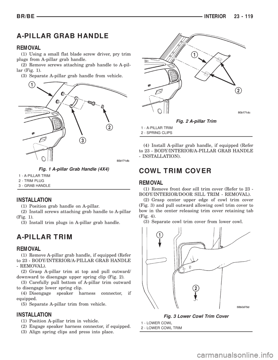
REMOVAL
(1) Using a small flat blade screw driver, pry trim
plugs from A-pillar grab handle.
(2) Remove screws attaching grab handle to A-pil-
lar (Fig. 1).
(3) Separate A-pillar grab handle from vehicle.
INSTALLATION
(1) Position grab handle on A-pillar.
(2) Install screws attaching grab handle to A-pillar
(Fig. 1).
(3) Install trim plugs in A-pillar grab handle.
A-PILLAR TRIM
REMOVAL
(1) Remove A-pillar grab handle, if equipped (Refer
to 23 - BODY/INTERIOR/A-PILLAR GRAB HANDLE
- REMOVAL).
(2) Grasp A-pillar trim at top and pull outward/
downward to disengage upper spring clip (Fig. 2).
(3) Carefully pull bottom of A-pillar trim outward
to disengage lower spring clip.
(4) Disengage speaker harness connector, if
equipped.
(5) Separate A-pillar trim from vehicle.
INSTALLATION
(1) Position A-pillar trim in vehicle.
(2) Engage speaker harness connector, if equipped.
(3) Align spring clips and press into place.(4) Install A-pillar grab handle, if equipped (Refer
to 23 - BODY/INTERIOR/A-PILLAR GRAB HANDLE
- INSTALLATION).
COWL TRIM COVER
REMOVAL
(1) Remove front door sill trim cover (Refer to 23 -
BODY/INTERIOR/DOOR SILL TRIM - REMOVAL).
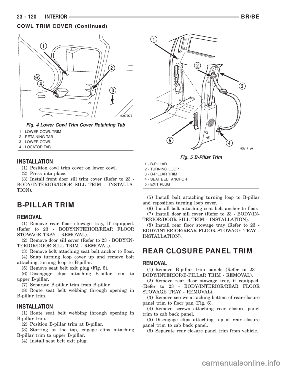
(2) Grasp center upper edge of cowl trim cover
(Fig. 3) and pull outward allowing cowl trim cover to
bow in the center releasing trim cover retaining tab
(Fig. 4).
(3) Separate cowl trim cover from lower cowl.
Fig. 1 A-pillar Grab Handle (4X4)
1 - A-PILLAR TRIM
2 - TRIM PLUG
3 - GRAB HANDLE
Fig. 2 A-pillar Trim
1 - A-PILLAR TRIM
2 - SPRING CLIPS
Fig. 3 Lower Cowl Trim Cover
1 - LOWER COWL
2 - LOWER COWL TRIM
BR/BEINTERIOR 23 - 119
Page 2693 of 2889
INSTALLATION
(1) Position cowl trim cover on lower cowl.
(2) Press into place.
(3) Install front door sill trim cover (Refer to 23 -
BODY/INTERIOR/DOOR SILL TRIM - INSTALLA-
TION).
B-PILLAR TRIM
REMOVAL
(1) Remove rear floor stowage tray, If equipped.
(Refer to 23 - BODY/INTERIOR/REAR FLOOR
STOWAGE TRAY - REMOVAL).
(2) Remove door sill cover (Refer to 23 - BODY/IN-
TERIOR/DOOR SILL TRIM - REMOVAL).
(3) Remove bolt attaching seat belt anchor to floor.
(4) Snap turning loop cover up and remove bolt
attaching turning loop to B-pillar.
(5) Remove seat belt exit plug (Fig. 5).
(6) Disengage clips attaching B-pillar trim to
upper B-pillar.
(7) Separate B-pillar trim from B-pillar.
(8) Route seat belt webbing through opening in
B-pillar trim.
INSTALLATION
(1) Route seat belt webbing through opening in
B-pillar trim.
(2) Position B-pillar trim at B-pillar.
(3) Starting at the top, engage clips attaching
B-pillar trim to upper B-pillar.
(4) Install seat belt exit plug.(5) Install bolt attaching turning loop to B-pillar
and reposition turning loop cover.
(6) Install bolt attaching seat belt anchor to floor.
(7) Install door sill cover (Refer to 23 - BODY/IN-
TERIOR/DOOR SILL TRIM - INSTALLATION).
(8) Install rear floor stowage tray (Refer to 23 -
BODY/INTERIOR/REAR FLOOR STOWAGE TRAY -
INSTALLATION).
REAR CLOSURE PANEL TRIM
REMOVAL
(1) Remove B-pillar trim panels (Refer to 23 -
BODY/INTERIOR/B-PILLAR TRIM - REMOVAL).
(2) Remove rear floor stowage tray, if equipped.
(Refer to 23 - BODY/INTERIOR/REAR FLOOR
STOWAGE TRAY - REMOVAL).
(3) Remove screws attaching bottom of rear closure
panel trim to floor pan (Fig. 6).
(4) Remove screws attaching rear closure panel
trim to cab back panel.
(5) Disengage clips attaching top of rear closure
panel trim to cab back panel.
(6) Separate rear closure panel trim from vehicle.
Fig. 4 Lower Cowl Trim Cover Retaining Tab
1 - LOWER COWL TRIM
2 - RETAINING TAB
3 - LOWER COWL
4 - LOCATOR TAB
Fig. 5 B-Pillar Trim
1 - B-PILLAR
2 - TURNING LOOP
3 - B-PILLAR TRIM
4 - SEAT BELT ANCHOR
5 - EXIT PLUG
23 - 120 INTERIORBR/BE
COWL TRIM COVER (Continued)