boot DODGE RAM 2001 Service Repair Manual
[x] Cancel search | Manufacturer: DODGE, Model Year: 2001, Model line: RAM, Model: DODGE RAM 2001Pages: 2889, PDF Size: 68.07 MB
Page 82 of 2889
PROPELLER SHAFT - REAR
REMOVAL
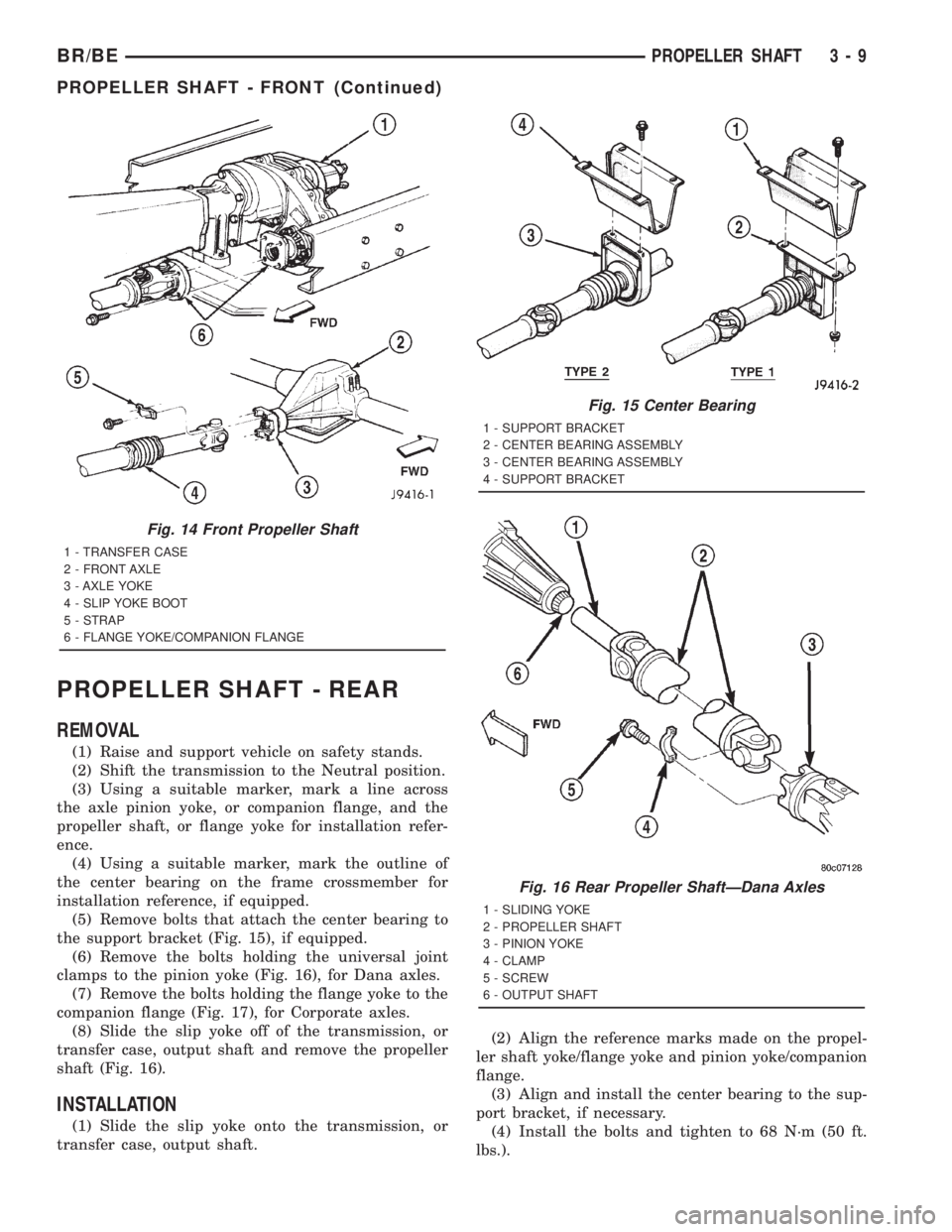
(1) Raise and support vehicle on safety stands.
(2) Shift the transmission to the Neutral position.
(3) Using a suitable marker, mark a line across
the axle pinion yoke, or companion flange, and the
propeller shaft, or flange yoke for installation refer-
ence.
(4) Using a suitable marker, mark the outline of
the center bearing on the frame crossmember for
installation reference, if equipped.
(5) Remove bolts that attach the center bearing to
the support bracket (Fig. 15), if equipped.
(6) Remove the bolts holding the universal joint
clamps to the pinion yoke (Fig. 16), for Dana axles.
(7) Remove the bolts holding the flange yoke to the
companion flange (Fig. 17), for Corporate axles.
(8) Slide the slip yoke off of the transmission, or
transfer case, output shaft and remove the propeller
shaft (Fig. 16).
INSTALLATION
(1) Slide the slip yoke onto the transmission, or
transfer case, output shaft.(2) Align the reference marks made on the propel-
ler shaft yoke/flange yoke and pinion yoke/companion
flange.
(3) Align and install the center bearing to the sup-
port bracket, if necessary.
(4) Install the bolts and tighten to 68 N´m (50 ft.
lbs.).
Fig. 14 Front Propeller Shaft
1 - TRANSFER CASE
2 - FRONT AXLE
3 - AXLE YOKE
4 - SLIP YOKE BOOT
5 - STRAP
6 - FLANGE YOKE/COMPANION FLANGE
Fig. 15 Center Bearing
1 - SUPPORT BRACKET
2 - CENTER BEARING ASSEMBLY
3 - CENTER BEARING ASSEMBLY
4 - SUPPORT BRACKET
Fig. 16 Rear Propeller ShaftÐDana Axles
1 - SLIDING YOKE
2 - PROPELLER SHAFT
3 - PINION YOKE
4 - CLAMP
5 - SCREW
6 - OUTPUT SHAFT
BR/BEPROPELLER SHAFT 3 - 9
PROPELLER SHAFT - FRONT (Continued)
Page 83 of 2889
(5) Position universal joint into pinion yoke for
Dana axles and tighten strap bolts to 29 N´m (22 ft.
lbs.).
(6) Position companion yoke onto the companion
flange for Corporate axles and tighten the bolts to
108 N´m (80 ft. lbs.).
(7) Lower the vehicle.
CENTER BEARING
DESCRIPTION
The two±piece propeller shaft uses a center bearing
to support the shafts. Two types of center bearings
are used. Type 1 is used with the 9 1/4 axle. Type 2
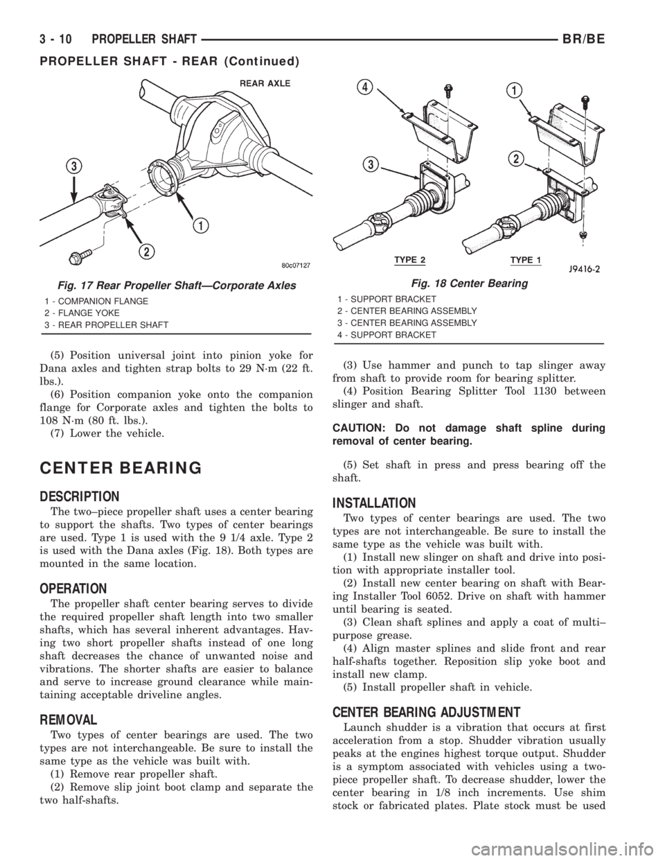
is used with the Dana axles (Fig. 18). Both types are
mounted in the same location.
OPERATION
The propeller shaft center bearing serves to divide
the required propeller shaft length into two smaller
shafts, which has several inherent advantages. Hav-
ing two short propeller shafts instead of one long
shaft decreases the chance of unwanted noise and
vibrations. The shorter shafts are easier to balance
and serve to increase ground clearance while main-
taining acceptable driveline angles.
REMOVAL
Two types of center bearings are used. The two
types are not interchangeable. Be sure to install the
same type as the vehicle was built with.
(1) Remove rear propeller shaft.
(2) Remove slip joint boot clamp and separate the
two half-shafts.(3) Use hammer and punch to tap slinger away
from shaft to provide room for bearing splitter.
(4) Position Bearing Splitter Tool 1130 between
slinger and shaft.
CAUTION: Do not damage shaft spline during
removal of center bearing.
(5) Set shaft in press and press bearing off the
shaft.
INSTALLATION
Two types of center bearings are used. The two
types are not interchangeable. Be sure to install the
same type as the vehicle was built with.
(1) Install new slinger on shaft and drive into posi-
tion with appropriate installer tool.
(2) Install new center bearing on shaft with Bear-
ing Installer Tool 6052. Drive on shaft with hammer
until bearing is seated.
(3) Clean shaft splines and apply a coat of multi±
purpose grease.
(4) Align master splines and slide front and rear
half-shafts together. Reposition slip yoke boot and
install new clamp.
(5) Install propeller shaft in vehicle.
CENTER BEARING ADJUSTMENT
Launch shudder is a vibration that occurs at first
acceleration from a stop. Shudder vibration usually
peaks at the engines highest torque output. Shudder
is a symptom associated with vehicles using a two-
piece propeller shaft. To decrease shudder, lower the
center bearing in 1/8 inch increments. Use shim
stock or fabricated plates. Plate stock must be used
Fig. 17 Rear Propeller ShaftÐCorporate Axles
1 - COMPANION FLANGE
2 - FLANGE YOKE
3 - REAR PROPELLER SHAFT
Fig. 18 Center Bearing
1 - SUPPORT BRACKET
2 - CENTER BEARING ASSEMBLY
3 - CENTER BEARING ASSEMBLY
4 - SUPPORT BRACKET
3 - 10 PROPELLER SHAFTBR/BE
PROPELLER SHAFT - REAR (Continued)
Page 275 of 2889
DESCRIPTION N´m Ft. Lbs. In. Lbs.
Park Brake Pedal
Assembly
Mounting Bolts/Nuts28 21 250
Hub/Bearing
LD 4x2 Spindle Nut251 185 Ð
Hub/Bearing
HD 4x2 Spindle Nut380 280 Ð
Hub/Bearing
4x4 Hub/Bearing Bolts170 125 Ð
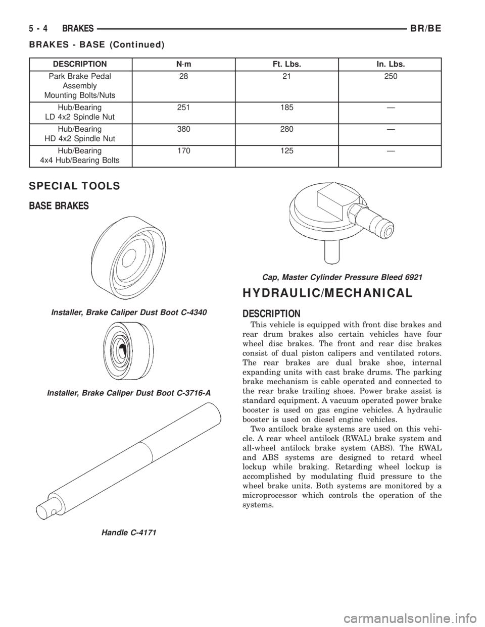
SPECIAL TOOLS
BASE BRAKES
HYDRAULIC/MECHANICAL
DESCRIPTION
This vehicle is equipped with front disc brakes and
rear drum brakes also certain vehicles have four
wheel disc brakes. The front and rear disc brakes
consist of dual piston calipers and ventilated rotors.
The rear brakes are dual brake shoe, internal
expanding units with cast brake drums. The parking
brake mechanism is cable operated and connected to
the rear brake trailing shoes. Power brake assist is
standard equipment. A vacuum operated power brake
booster is used on gas engine vehicles. A hydraulic
booster is used on diesel engine vehicles.
Two antilock brake systems are used on this vehi-
cle. A rear wheel antilock (RWAL) brake system and
all-wheel antilock brake system (ABS). The RWAL
and ABS systems are designed to retard wheel
lockup while braking. Retarding wheel lockup is
accomplished by modulating fluid pressure to the
wheel brake units. Both systems are monitored by a
microprocessor which controls the operation of the
systems.
Installer, Brake Caliper Dust Boot C-4340
Installer, Brake Caliper Dust Boot C-3716-A
Handle C-4171
Cap, Master Cylinder Pressure Bleed 6921
5 - 4 BRAKESBR/BE
BRAKES - BASE (Continued)
Page 282 of 2889
DISASSEMBLY
(1) Drain the brake fluid from caliper.
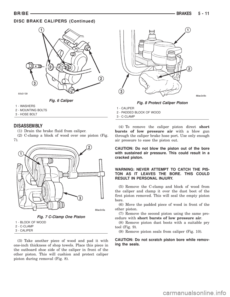
(2) C-clamp a block of wood over one piston (Fig.
7).
(3) Take another piece of wood and pad it with
one-inch thickness of shop towels. Place this piece in
the outboard shoe side of the caliper in front of the
other piston. This will cushion and protect caliper
piston during removal (Fig. 8).(4) To remove the caliper piston directshort
bursts of low pressure airwith a blow gun
through the caliper brake hose port. Use only enough
air pressure to ease the piston out.
CAUTION: Do not blow the piston out of the bore
with sustained air pressure. This could result in a
cracked piston.
WARNING: NEVER ATTEMPT TO CATCH THE PIS-
TON AS IT LEAVES THE BORE. THIS COULD
RESULT IN PERSONAL INJURY.
(5) Remove the C-clamp and block of wood from
the caliper and clamp it over the dust boot of the
first piston removed. This will seal the empty piston
bore.
(6) Move the padded piece of wood in front of the
other piston.
(7) Remove the second piston using the same pro-
cedure withshort bursts of low pressure air.
(8) Remove piston dust boots with a suitable pry
tool (Fig. 9).
(9) Remove piston seals from caliper (Fig. 10).
CAUTION: Do not scratch piston bore while remov-
ing the seals.
Fig. 6 Caliper
1 - WASHERS
2 - MOUNTING BOLTS
3 - HOSE BOLT
Fig. 7 C-Clamp One Piston
1 - BLOCK OF WOOD
2 - C-CLAMP
3 - CALIPER
Fig. 8 Protect Caliper Piston
1 - CALIPER
2 - PADDED BLOCK OF WOOD
3 - C-CLAMP
BR/BEBRAKES 5 - 11
DISC BRAKE CALIPERS (Continued)
Page 283 of 2889
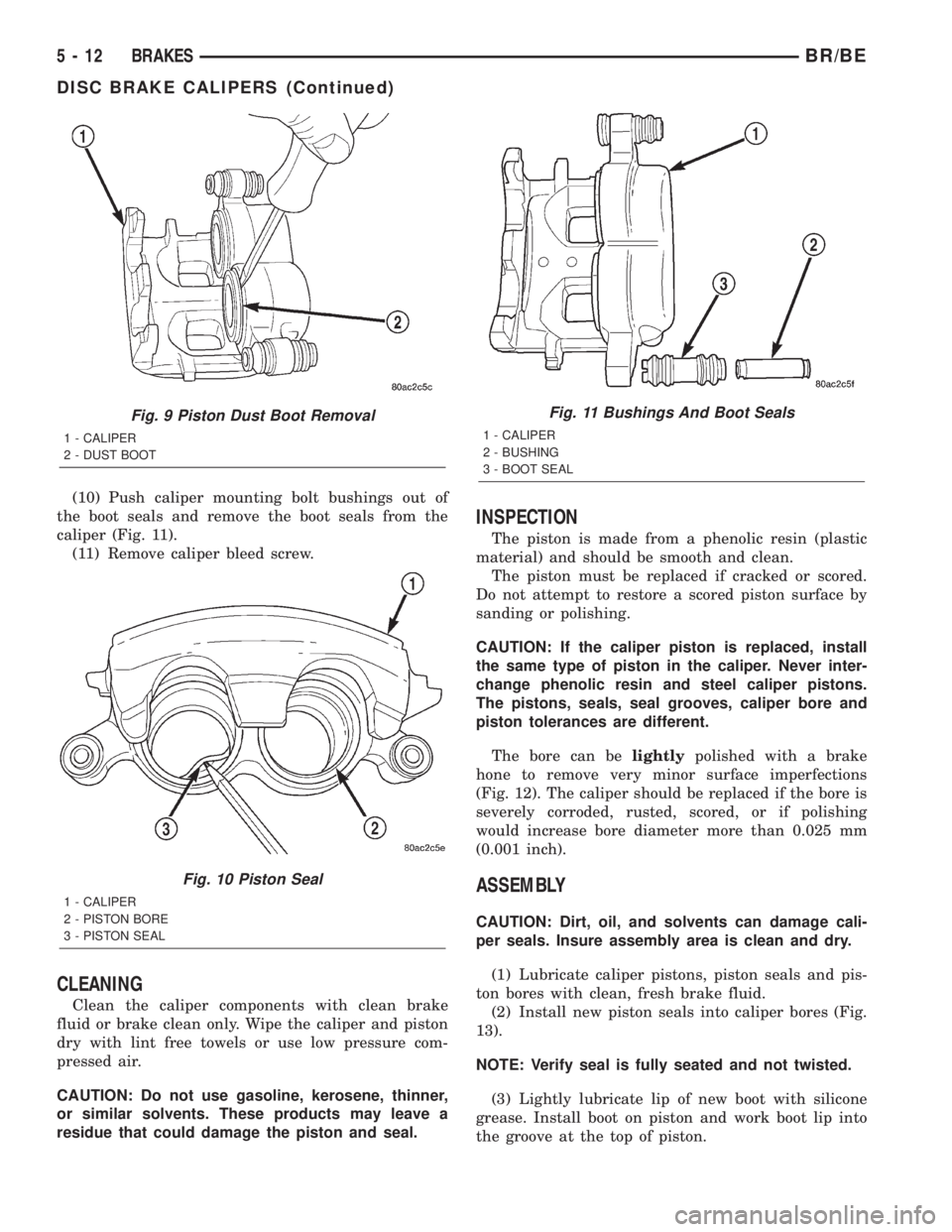
(10) Push caliper mounting bolt bushings out of
the boot seals and remove the boot seals from the
caliper (Fig. 11).
(11) Remove caliper bleed screw.
CLEANING
Clean the caliper components with clean brake
fluid or brake clean only. Wipe the caliper and piston
dry with lint free towels or use low pressure com-
pressed air.
CAUTION: Do not use gasoline, kerosene, thinner,
or similar solvents. These products may leave a
residue that could damage the piston and seal.
INSPECTION
The piston is made from a phenolic resin (plastic
material) and should be smooth and clean.
The piston must be replaced if cracked or scored.
Do not attempt to restore a scored piston surface by
sanding or polishing.
CAUTION: If the caliper piston is replaced, install
the same type of piston in the caliper. Never inter-
change phenolic resin and steel caliper pistons.
The pistons, seals, seal grooves, caliper bore and
piston tolerances are different.
The bore can belightlypolished with a brake
hone to remove very minor surface imperfections
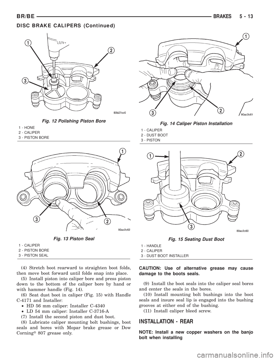
(Fig. 12). The caliper should be replaced if the bore is
severely corroded, rusted, scored, or if polishing
would increase bore diameter more than 0.025 mm
(0.001 inch).
ASSEMBLY
CAUTION: Dirt, oil, and solvents can damage cali-
per seals. Insure assembly area is clean and dry.
(1) Lubricate caliper pistons, piston seals and pis-
ton bores with clean, fresh brake fluid.
(2) Install new piston seals into caliper bores (Fig.
13).
NOTE: Verify seal is fully seated and not twisted.
(3) Lightly lubricate lip of new boot with silicone
grease. Install boot on piston and work boot lip into
the groove at the top of piston.
Fig. 9 Piston Dust Boot Removal
1 - CALIPER
2 - DUST BOOT
Fig. 10 Piston Seal
1 - CALIPER
2 - PISTON BORE
3 - PISTON SEAL
Fig. 11 Bushings And Boot Seals
1 - CALIPER
2 - BUSHING
3 - BOOT SEAL
5 - 12 BRAKESBR/BE
DISC BRAKE CALIPERS (Continued)
Page 284 of 2889
(4) Stretch boot rearward to straighten boot folds,
then move boot forward until folds snap into place.
(5) Install piston into caliper bore and press piston
down to the bottom of the caliper bore by hand or
with hammer handle (Fig. 14).
(6) Seat dust boot in caliper (Fig. 15) with Handle
C-4171 and Installer:
²HD 56 mm caliper: Installer C-4340
²LD 54 mm caliper: Installer C-3716-A
(7) Install the second piston and dust boot.
(8) Lubricate caliper mounting bolt bushings, boot
seals and bores with Mopar brake grease or Dow
Corningt807 grease only.CAUTION: Use of alternative grease may cause
damage to the boots seals.
(9) Install the boot seals into the caliper seal bores
and center the seals in the bores.
(10) Install mounting bolt bushings into the boot
seals and insure seal lip is engaged into the bushing
grooves at either end of the bushing.
(11) Install caliper bleed screw.
INSTALLATION - REAR
NOTE: Install a new copper washers on the banjo
bolt when installing
Fig. 12 Polishing Piston Bore
1 - HONE
2 - CALIPER
3 - PISTON BORE
Fig. 13 Piston Seal
1 - CALIPER
2 - PISTON BORE
3 - PISTON SEAL
Fig. 14 Caliper Piston Installation
1 - CALIPER
2 - DUST BOOT
3 - PISTON
Fig. 15 Seating Dust Boot
1 - HANDLE
2 - CALIPER
3 - DUST BOOT INSTALLER
BR/BEBRAKES 5 - 13
DISC BRAKE CALIPERS (Continued)
Page 302 of 2889
(4) Bleed base brake system, (Refer to 5 -
BRAKES/HYDRAULIC/MECHANICAL - STAN-
DARD PROCEDURE)
WHEEL CYLINDERS
REMOVAL
(1) Raise vehicle and remove tire and wheel
assembly.
(2) Remove brake drum.
(3) Lift adjuster lever away from adjuster screw.
Then turn screw star wheel until screw is fully
retracted.
(4) Remove brake shoe return springs, adjuster
spring and adjuster screw. Move upper ends of brake
shoes apart to provide removal clearance for wheel
cylinder links.
(5) Disconnect brake line from wheel cylinder.
(6) Remove wheel cylinder attaching screws and
remove cylinder from support plate
DISASSEMBLY
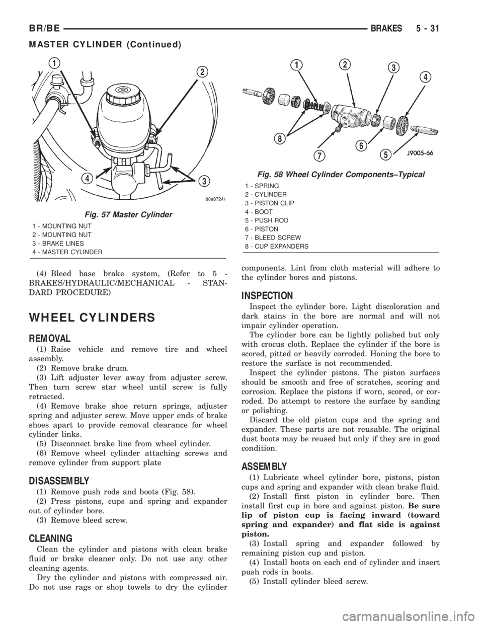
(1) Remove push rods and boots (Fig. 58).
(2) Press pistons, cups and spring and expander
out of cylinder bore.
(3) Remove bleed screw.
CLEANING
Clean the cylinder and pistons with clean brake
fluid or brake cleaner only. Do not use any other
cleaning agents.
Dry the cylinder and pistons with compressed air.
Do not use rags or shop towels to dry the cylindercomponents. Lint from cloth material will adhere to
the cylinder bores and pistons.
INSPECTION
Inspect the cylinder bore. Light discoloration and
dark stains in the bore are normal and will not
impair cylinder operation.
The cylinder bore can be lightly polished but only
with crocus cloth. Replace the cylinder if the bore is
scored, pitted or heavily corroded. Honing the bore to
restore the surface is not recommended.
Inspect the cylinder pistons. The piston surfaces
should be smooth and free of scratches, scoring and
corrosion. Replace the pistons if worn, scored, or cor-
roded. Do attempt to restore the surface by sanding
or polishing.
Discard the old piston cups and the spring and
expander. These parts are not reusable. The original
dust boots may be reused but only if they are in good
condition.
ASSEMBLY
(1) Lubricate wheel cylinder bore, pistons, piston
cups and spring and expander with clean brake fluid.
(2) Install first piston in cylinder bore. Then
install first cup in bore and against piston.Be sure
lip of piston cup is facing inward (toward
spring and expander) and flat side is against
piston.
(3) Install spring and expander followed by
remaining piston cup and piston.
(4) Install boots on each end of cylinder and insert
push rods in boots.
(5) Install cylinder bleed screw.
Fig. 57 Master Cylinder
1 - MOUNTING NUT
2 - MOUNTING NUT
3 - BRAKE LINES
4 - MASTER CYLINDER
Fig. 58 Wheel Cylinder Components±Typical
1 - SPRING
2 - CYLINDER
3 - PISTON CLIP
4 - BOOT
5 - PUSH ROD
6 - PISTON
7 - BLEED SCREW
8 - CUP EXPANDERS
BR/BEBRAKES 5 - 31
MASTER CYLINDER (Continued)
Page 326 of 2889
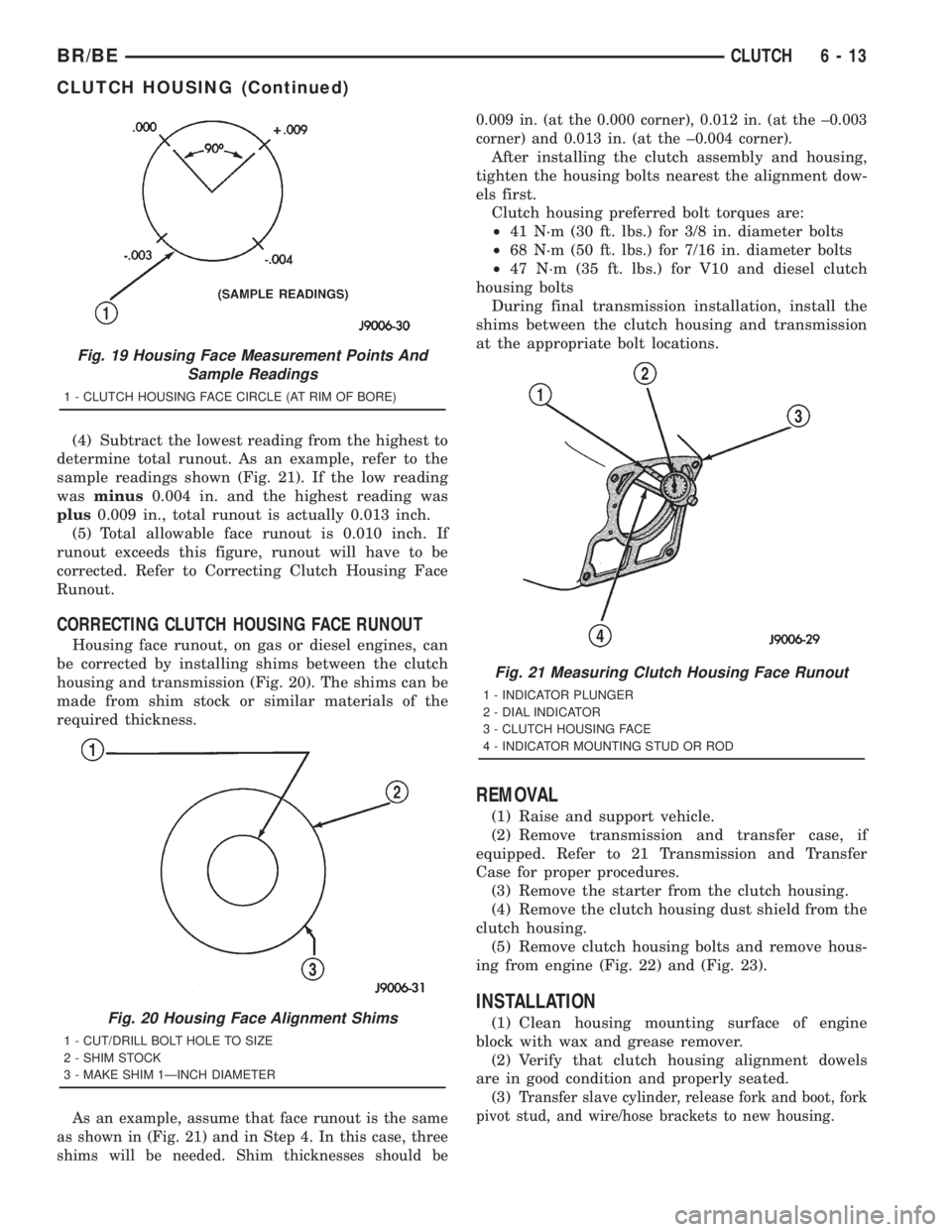
(4) Subtract the lowest reading from the highest to
determine total runout. As an example, refer to the
sample readings shown (Fig. 21). If the low reading
wasminus0.004 in. and the highest reading was
plus0.009 in., total runout is actually 0.013 inch.
(5) Total allowable face runout is 0.010 inch. If
runout exceeds this figure, runout will have to be
corrected. Refer to Correcting Clutch Housing Face
Runout.
CORRECTING CLUTCH HOUSING FACE RUNOUT
Housing face runout, on gas or diesel engines, can
be corrected by installing shims between the clutch
housing and transmission (Fig. 20). The shims can be
made from shim stock or similar materials of the
required thickness.
As an example, assume that face runout is the same
as shown in (Fig. 21) and in Step 4. In this case, three
shims will be needed. Shim thicknesses should be0.009 in. (at the 0.000 corner), 0.012 in. (at the ±0.003
corner) and 0.013 in. (at the ±0.004 corner).
After installing the clutch assembly and housing,
tighten the housing bolts nearest the alignment dow-
els first.
Clutch housing preferred bolt torques are:
²41 N´m (30 ft. lbs.) for 3/8 in. diameter bolts
²68 N´m (50 ft. lbs.) for 7/16 in. diameter bolts
²47 N´m (35 ft. lbs.) for V10 and diesel clutch
housing bolts
During final transmission installation, install the
shims between the clutch housing and transmission
at the appropriate bolt locations.
REMOVAL
(1) Raise and support vehicle.
(2) Remove transmission and transfer case, if
equipped. Refer to 21 Transmission and Transfer
Case for proper procedures.
(3) Remove the starter from the clutch housing.
(4) Remove the clutch housing dust shield from the
clutch housing.
(5) Remove clutch housing bolts and remove hous-
ing from engine (Fig. 22) and (Fig. 23).
INSTALLATION
(1) Clean housing mounting surface of engine
block with wax and grease remover.
(2) Verify that clutch housing alignment dowels
are in good condition and properly seated.
(3)
Transfer slave cylinder, release fork and boot, fork
pivot stud, and wire/hose brackets to new housing.
Fig. 19 Housing Face Measurement Points And
Sample Readings
1 - CLUTCH HOUSING FACE CIRCLE (AT RIM OF BORE)
Fig. 20 Housing Face Alignment Shims
1 - CUT/DRILL BOLT HOLE TO SIZE
2 - SHIM STOCK
3 - MAKE SHIM 1ÐINCH DIAMETER
Fig. 21 Measuring Clutch Housing Face Runout
1 - INDICATOR PLUNGER
2 - DIAL INDICATOR
3 - CLUTCH HOUSING FACE
4 - INDICATOR MOUNTING STUD OR ROD
BR/BECLUTCH 6 - 13
CLUTCH HOUSING (Continued)
Page 511 of 2889
REMOVAL
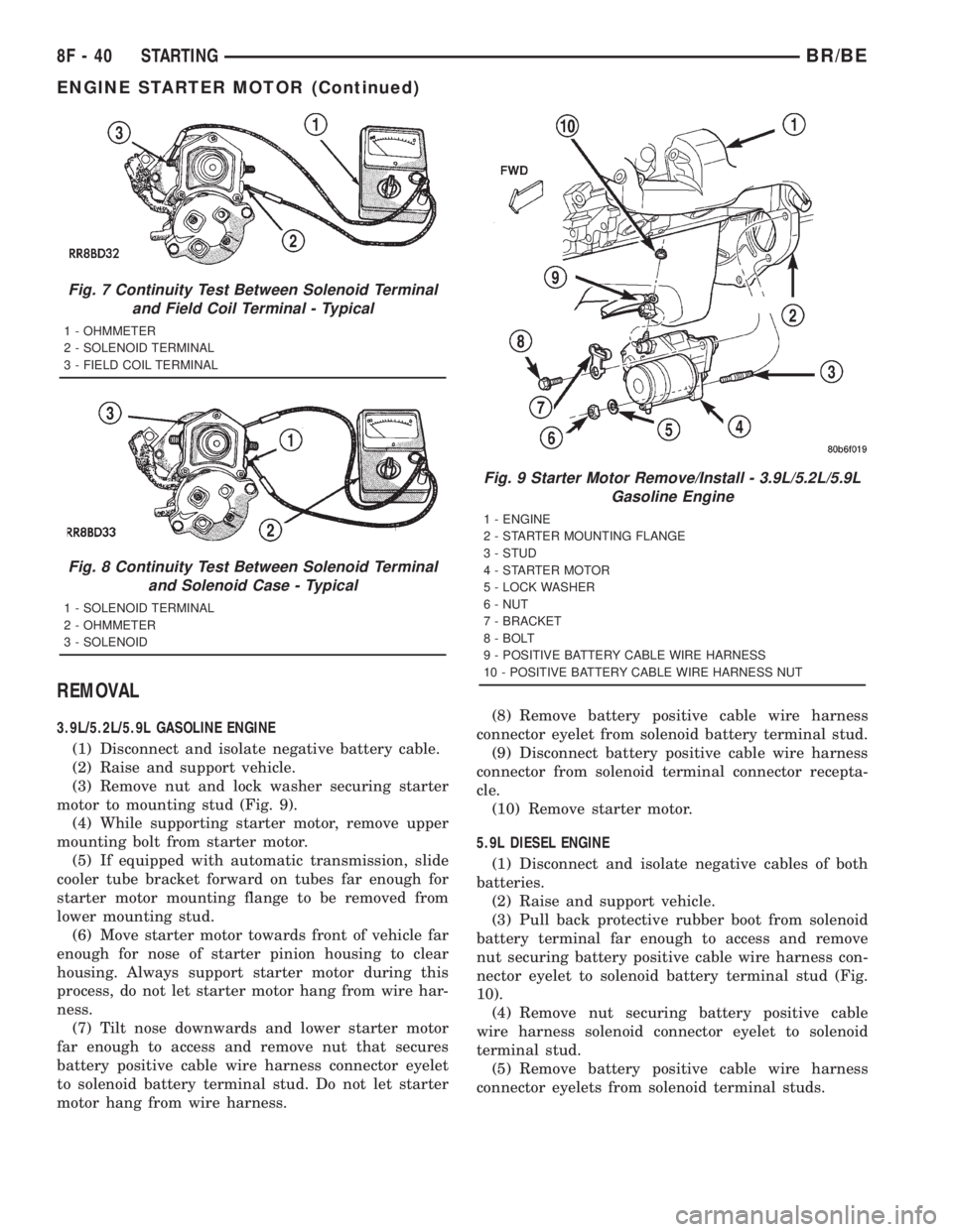
3.9L/5.2L/5.9L GASOLINE ENGINE
(1) Disconnect and isolate negative battery cable.
(2) Raise and support vehicle.
(3) Remove nut and lock washer securing starter
motor to mounting stud (Fig. 9).
(4) While supporting starter motor, remove upper
mounting bolt from starter motor.
(5) If equipped with automatic transmission, slide
cooler tube bracket forward on tubes far enough for
starter motor mounting flange to be removed from
lower mounting stud.
(6) Move starter motor towards front of vehicle far
enough for nose of starter pinion housing to clear
housing. Always support starter motor during this
process, do not let starter motor hang from wire har-
ness.
(7) Tilt nose downwards and lower starter motor
far enough to access and remove nut that secures
battery positive cable wire harness connector eyelet
to solenoid battery terminal stud. Do not let starter
motor hang from wire harness.(8) Remove battery positive cable wire harness
connector eyelet from solenoid battery terminal stud.
(9) Disconnect battery positive cable wire harness
connector from solenoid terminal connector recepta-
cle.
(10) Remove starter motor.
5.9L DIESEL ENGINE
(1) Disconnect and isolate negative cables of both
batteries.
(2) Raise and support vehicle.
(3) Pull back protective rubber boot from solenoid
battery terminal far enough to access and remove
nut securing battery positive cable wire harness con-
nector eyelet to solenoid battery terminal stud (Fig.
10).
(4) Remove nut securing battery positive cable
wire harness solenoid connector eyelet to solenoid
terminal stud.
(5) Remove battery positive cable wire harness
connector eyelets from solenoid terminal studs.
Fig. 7 Continuity Test Between Solenoid Terminal
and Field Coil Terminal - Typical
1 - OHMMETER
2 - SOLENOID TERMINAL
3 - FIELD COIL TERMINAL
Fig. 8 Continuity Test Between Solenoid Terminal
and Solenoid Case - Typical
1 - SOLENOID TERMINAL
2 - OHMMETER
3 - SOLENOID
Fig. 9 Starter Motor Remove/Install - 3.9L/5.2L/5.9L
Gasoline Engine
1 - ENGINE
2 - STARTER MOUNTING FLANGE
3 - STUD
4 - STARTER MOTOR
5 - LOCK WASHER
6 - NUT
7 - BRACKET
8 - BOLT
9 - POSITIVE BATTERY CABLE WIRE HARNESS
10 - POSITIVE BATTERY CABLE WIRE HARNESS NUT
8F - 40 STARTINGBR/BE
ENGINE STARTER MOTOR (Continued)
Page 513 of 2889
5.9L DIESEL ENGINE
(1) If equipped, position aluminum spacer to rear
of starter.
(2) Position starter motor to engine.
(3) Support starter and loosely install three
mounting bolts.
(4) Tighten 3 bolts to 43.4 N´m (32 ft. lbs.).
(5) Position wiring eyelets to starter studs and
install nuts. Tighten small nut to 6.2 N´m (55 in.
lbs.). Tighten large nut to 13.6 N´m (120 in. lbs.).
(6) Install protective rubber boot over stud.
(7) Lower vehicle.
(8) Connect battery cables to both batteries.
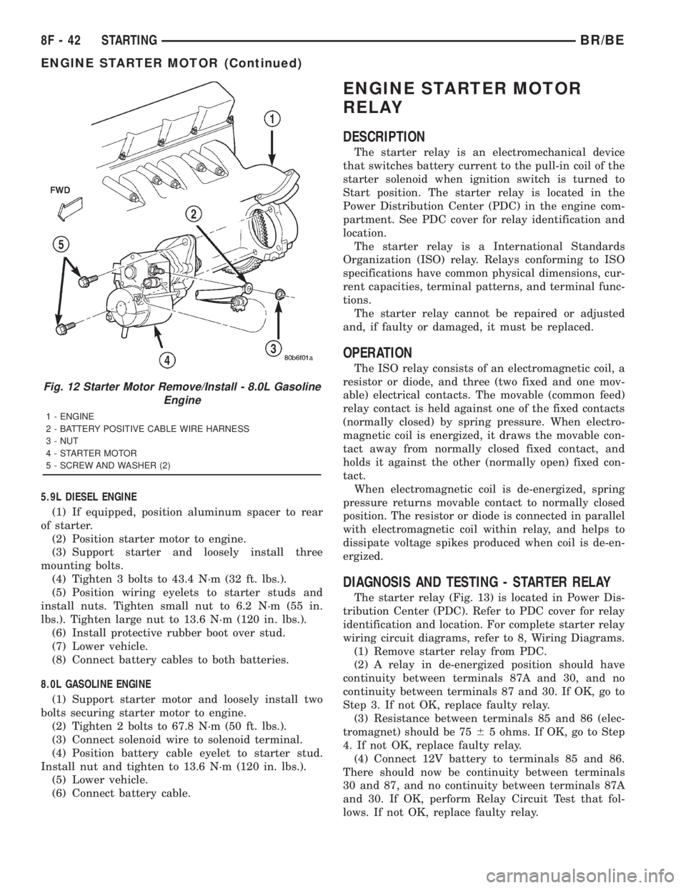
8.0L GASOLINE ENGINE
(1) Support starter motor and loosely install two
bolts securing starter motor to engine.
(2) Tighten 2 bolts to 67.8 N´m (50 ft. lbs.).
(3) Connect solenoid wire to solenoid terminal.
(4) Position battery cable eyelet to starter stud.
Install nut and tighten to 13.6 N´m (120 in. lbs.).
(5) Lower vehicle.
(6) Connect battery cable.
ENGINE STARTER MOTOR
RELAY
DESCRIPTION
The starter relay is an electromechanical device
that switches battery current to the pull-in coil of the
starter solenoid when ignition switch is turned to
Start position. The starter relay is located in the
Power Distribution Center (PDC) in the engine com-
partment. See PDC cover for relay identification and
location.
The starter relay is a International Standards
Organization (ISO) relay. Relays conforming to ISO
specifications have common physical dimensions, cur-
rent capacities, terminal patterns, and terminal func-
tions.
The starter relay cannot be repaired or adjusted
and, if faulty or damaged, it must be replaced.
OPERATION
The ISO relay consists of an electromagnetic coil, a
resistor or diode, and three (two fixed and one mov-
able) electrical contacts. The movable (common feed)
relay contact is held against one of the fixed contacts
(normally closed) by spring pressure. When electro-
magnetic coil is energized, it draws the movable con-
tact away from normally closed fixed contact, and
holds it against the other (normally open) fixed con-
tact.
When electromagnetic coil is de-energized, spring
pressure returns movable contact to normally closed
position. The resistor or diode is connected in parallel
with electromagnetic coil within relay, and helps to
dissipate voltage spikes produced when coil is de-en-
ergized.
DIAGNOSIS AND TESTING - STARTER RELAY
The starter relay (Fig. 13) is located in Power Dis-
tribution Center (PDC). Refer to PDC cover for relay
identification and location. For complete starter relay
wiring circuit diagrams, refer to 8, Wiring Diagrams.
(1) Remove starter relay from PDC.
(2) A relay in de-energized position should have
continuity between terminals 87A and 30, and no
continuity between terminals 87 and 30. If OK, go to
Step 3. If not OK, replace faulty relay.
(3) Resistance between terminals 85 and 86 (elec-
tromagnet) should be 7565 ohms. If OK, go to Step
4. If not OK, replace faulty relay.
(4) Connect 12V battery to terminals 85 and 86.
There should now be continuity between terminals
30 and 87, and no continuity between terminals 87A
and 30. If OK, perform Relay Circuit Test that fol-
lows. If not OK, replace faulty relay.
Fig. 12 Starter Motor Remove/Install - 8.0L Gasoline
Engine
1 - ENGINE
2 - BATTERY POSITIVE CABLE WIRE HARNESS
3 - NUT
4 - STARTER MOTOR
5 - SCREW AND WASHER (2)
8F - 42 STARTINGBR/BE
ENGINE STARTER MOTOR (Continued)