Frame DODGE RAM 2001 Service Repair Manual
[x] Cancel search | Manufacturer: DODGE, Model Year: 2001, Model line: RAM, Model: DODGE RAM 2001Pages: 2889, PDF Size: 68.07 MB
Page 1 of 2889
GROUP TAB LOCATOR
Introduction
0Lubrication & Maintenance
2Suspension
3Differential & Driveline
5Brakes
7Cooling
8AAudio
8BChime/Buzzer
8EElectronic Control Modules
8FEngine Systems
8GHeated Systems
8HHorn
8IIgnition Control
8JInstrument Cluster
8LLamps
8MMessage Systems
8NPower Systems
8ORestraints
8PSpeed Control
8QVehicle Theft Security
8RWipers/Washers
8WWiring
9Engine
11Exhaust System
13Frame & Bumpers
14Fuel System
19Steering
21Transmission/Transaxle
22Tires/Wheels
23Body
24Heating & Air Conditioning
25Emissions Control Systems
30New Vehicle Preparation
Component and System Index
Service Manual Comment Forms (Rear of Manual)
Page 11 of 2889
VECI LABEL
DESCRIPTION
Vehicles equipped with 3.9L V-6 or 5.2L/5.9L V-8
LDC-gas powered engines have a VECI label.
The label combines both emission control informa-
tion and vacuum hose routing. This label is located
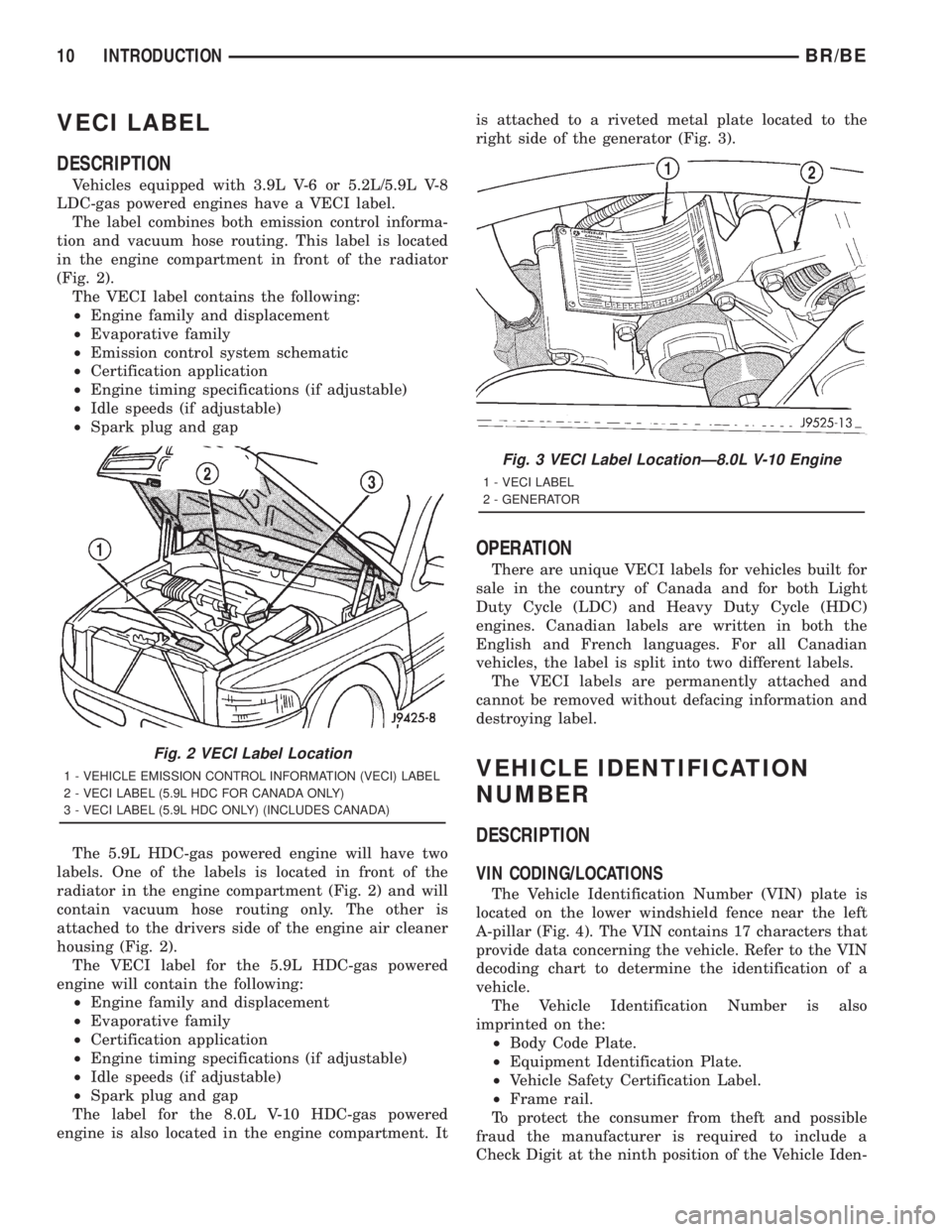
in the engine compartment in front of the radiator
(Fig. 2).
The VECI label contains the following:
²Engine family and displacement
²Evaporative family
²Emission control system schematic
²Certification application
²Engine timing specifications (if adjustable)
²Idle speeds (if adjustable)
²Spark plug and gap
The 5.9L HDC-gas powered engine will have two
labels. One of the labels is located in front of the
radiator in the engine compartment (Fig. 2) and will
contain vacuum hose routing only. The other is
attached to the drivers side of the engine air cleaner
housing (Fig. 2).
The VECI label for the 5.9L HDC-gas powered
engine will contain the following:
²Engine family and displacement
²Evaporative family
²Certification application
²Engine timing specifications (if adjustable)
²Idle speeds (if adjustable)
²Spark plug and gap
The label for the 8.0L V-10 HDC-gas powered
engine is also located in the engine compartment. Itis attached to a riveted metal plate located to the
right side of the generator (Fig. 3).
OPERATION
There are unique VECI labels for vehicles built for
sale in the country of Canada and for both Light
Duty Cycle (LDC) and Heavy Duty Cycle (HDC)
engines. Canadian labels are written in both the
English and French languages. For all Canadian
vehicles, the label is split into two different labels.
The VECI labels are permanently attached and
cannot be removed without defacing information and
destroying label.
VEHICLE IDENTIFICATION
NUMBER
DESCRIPTION
VIN CODING/LOCATIONS
The Vehicle Identification Number (VIN) plate is
located on the lower windshield fence near the left
A-pillar (Fig. 4). The VIN contains 17 characters that
provide data concerning the vehicle. Refer to the VIN
decoding chart to determine the identification of a
vehicle.
The Vehicle Identification Number is also
imprinted on the:
²Body Code Plate.
²Equipment Identification Plate.
²Vehicle Safety Certification Label.
²Frame rail.
To protect the consumer from theft and possible
fraud the manufacturer is required to include a
Check Digit at the ninth position of the Vehicle Iden-
Fig. 2 VECI Label Location
1 - VEHICLE EMISSION CONTROL INFORMATION (VECI) LABEL
2 - VECI LABEL (5.9L HDC FOR CANADA ONLY)
3 - VECI LABEL (5.9L HDC ONLY) (INCLUDES CANADA)
Fig. 3 VECI Label LocationÐ8.0L V-10 Engine
1 - VECI LABEL
2 - GENERATOR
10 INTRODUCTIONBR/BE
Page 41 of 2889
DISCONNECT CABLE CLAMPS AS FOLLOWS:
²Disconnect BLACK cable clamp from engine
ground on disabled vehicle.
²When using a Booster vehicle, disconnect
BLACK cable clamp from battery negative terminal.
Disconnect RED cable clamp from battery positive
terminal.
²Disconnect RED cable clamp from battery posi-
tive terminal on disabled vehicle.
HOISTING
STANDARD PROCEDURE
Refer to the Owner's Manual for emergency vehicle
lifting procedures.
WARNING: THE HOISTING AND JACK LIFTING
POINTS PROVIDED ARE FOR A COMPLETE VEHI-
CLE. WHEN A CHASSIS OR DRIVETRAIN COMPO-
NENT IS REMOVED FROM A VEHICLE, THE
CENTER OF GRAVITY IS ALTERED MAKING SOME
HOISTING CONDITIONS UNSTABLE. PROPERLY
SUPPORT (Fig. 9) OR SECURE VEHICLE TO HOIST-
ING DEVICE WHEN THESE CONDITIONS EXIST.
FLOOR JACK
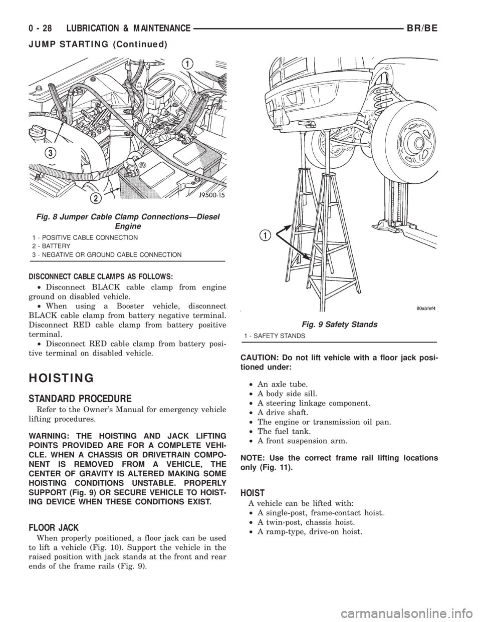
When properly positioned, a floor jack can be used
to lift a vehicle (Fig. 10). Support the vehicle in the
raised position with jack stands at the front and rear
ends of the frame rails (Fig. 9).CAUTION: Do not lift vehicle with a floor jack posi-
tioned under:
²An axle tube.
²A body side sill.
²A steering linkage component.
²A drive shaft.
²The engine or transmission oil pan.
²The fuel tank.
²A front suspension arm.
NOTE: Use the correct frame rail lifting locations
only (Fig. 11).
HOIST
A vehicle can be lifted with:
²A single-post, frame-contact hoist.
²A twin-post, chassis hoist.
²A ramp-type, drive-on hoist.
Fig. 8 Jumper Cable Clamp ConnectionsÐDiesel
Engine
1 - POSITIVE CABLE CONNECTION
2 - BATTERY
3 - NEGATIVE OR GROUND CABLE CONNECTION
Fig. 9 Safety Stands
1 - SAFETY STANDS
0 - 28 LUBRICATION & MAINTENANCEBR/BE
JUMP STARTING (Continued)
Page 42 of 2889
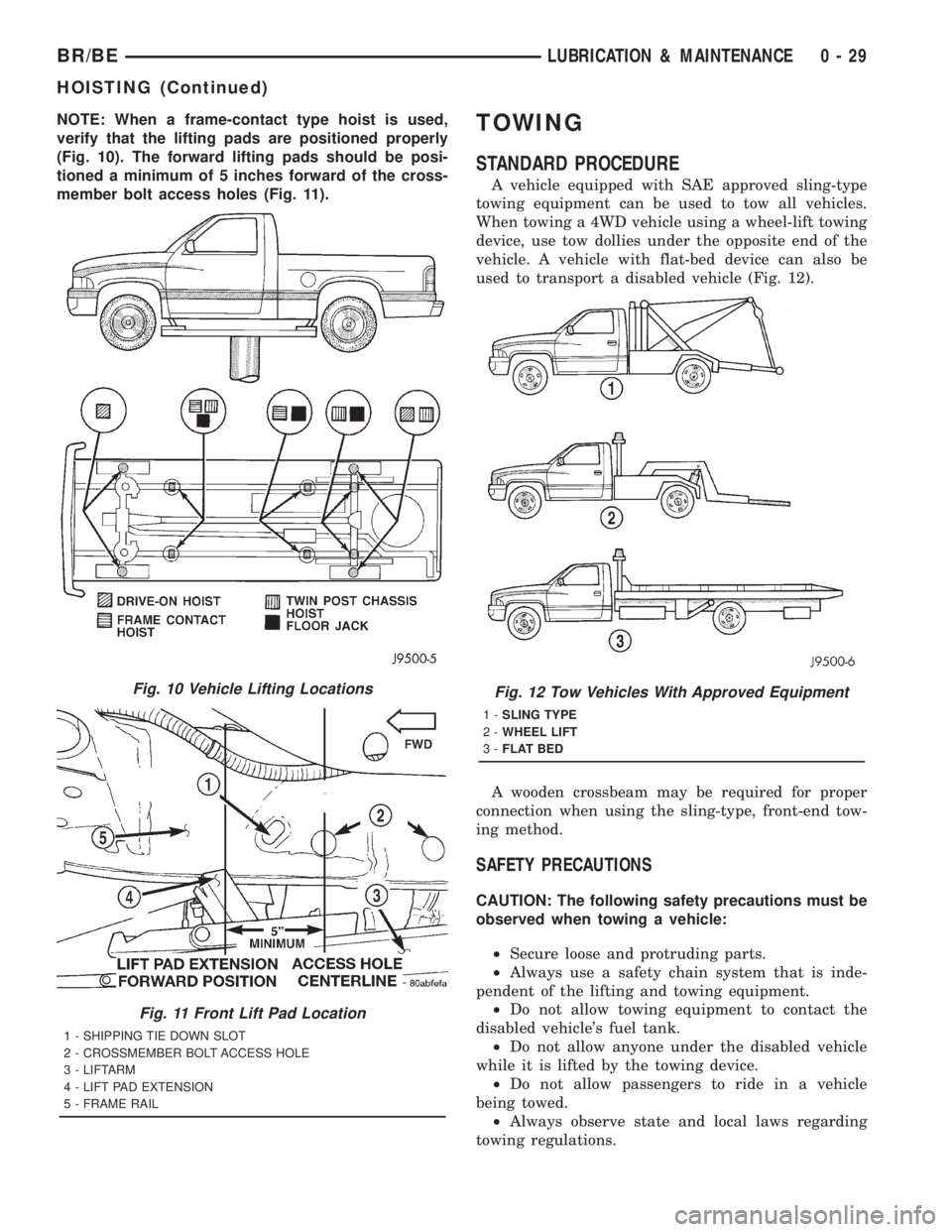
NOTE: When a frame-contact type hoist is used,
verify that the lifting pads are positioned properly
(Fig. 10). The forward lifting pads should be posi-
tioned a minimum of 5 inches forward of the cross-
member bolt access holes (Fig. 11).TOWING
STANDARD PROCEDURE
A vehicle equipped with SAE approved sling-type
towing equipment can be used to tow all vehicles.
When towing a 4WD vehicle using a wheel-lift towing
device, use tow dollies under the opposite end of the
vehicle. A vehicle with flat-bed device can also be
used to transport a disabled vehicle (Fig. 12).
A wooden crossbeam may be required for proper
connection when using the sling-type, front-end tow-
ing method.
SAFETY PRECAUTIONS
CAUTION: The following safety precautions must be
observed when towing a vehicle:
²Secure loose and protruding parts.
²Always use a safety chain system that is inde-
pendent of the lifting and towing equipment.
²Do not allow towing equipment to contact the
disabled vehicle's fuel tank.
²Do not allow anyone under the disabled vehicle
while it is lifted by the towing device.
²Do not allow passengers to ride in a vehicle
being towed.
²Always observe state and local laws regarding
towing regulations.
Fig. 10 Vehicle Lifting Locations
Fig. 11 Front Lift Pad Location
1 - SHIPPING TIE DOWN SLOT
2 - CROSSMEMBER BOLT ACCESS HOLE
3 - LIFTARM
4 - LIFT PAD EXTENSION
5 - FRAME RAIL
Fig. 12 Tow Vehicles With Approved Equipment
1-SLING TYPE
2-WHEEL LIFT
3-FLAT BED
BR/BELUBRICATION & MAINTENANCE 0 - 29
HOISTING (Continued)
Page 43 of 2889
²Do not tow a vehicle in a manner that could
jeopardize the safety of the operator, pedestrians or
other motorists.
²Do not attach tow chains, T-hooks, J-hooks, or a
tow sling to a bumper, steering linkage, drive shafts
or a non-reinforced frame hole.
²Do not tow a heavily loaded vehicle. Damage to
the cab, cargo box or frame may result. Use a flatbed
device to transport a loaded vehicle.
GROUND CLEARANCE
CAUTION: If vehicle is towed with wheels removed,
install lug nuts to retain brake drums or rotors.
A towed vehicle should be raised until lifted wheels
are a minimum 100 mm (4 in) from the ground. Be
sure there is adequate ground clearance at the oppo-
site end of the vehicle, especially when towing over
rough terrain or steep rises in the road. If necessary,
remove the wheels from the lifted end of the vehicle
and lower the vehicle closer to the ground, to
increase the ground clearance at the opposite end of
the vehicle. Install lug nuts on wheel attaching studs
to retain brake drums or rotors.
RAMP ANGLE
If a vehicle with flat-bed towing equipment is used,
the approach ramp angle should not exceed 15
degrees.
TOWING WHEN KEYS ARE NOT AVAILABLE
When the vehicle is locked and keys are not avail-
able, use a flat bed hauler. A Wheel-lift or Sling-type
device can be used on 4WD vehicles providedall the
wheels are lifted off the ground using tow dol-
lies.
FOUR-WHEEL-DRIVE VEHICLE TOWING
Chrysler Corporation recommends that a vehicle be
transported on a flat-bed device. A Wheel-lift or
Sling-type device can be used providedall the
wheels are lifted off the ground using tow dol-
lies.
WARNING: WHEN TOWING A DISABLED VEHICLE
AND THE DRIVE WHEELS ARE SECURED IN A
WHEEL LIFT OR TOW DOLLIES, ENSURE THE
TRANSMISSION IS IN THE PARK POSITION (AUTO-
MATIC TRANSMISSION) OR A FORWARD DRIVE
GEAR (MANUAL TRANSMISSION).
CAUTION: Many vehicles are equipped with air
dams, spoilers, and/or ground effect panels. To
avoid component damage, a wheel-lift towing vehi-
cle or a flat-bed hauling vehicle is recommended.
0 - 30 LUBRICATION & MAINTENANCEBR/BE
TOWING (Continued)
Page 46 of 2889
down several times. Always release the bumper in
the down position.Set the front end alignment to
specifications while the vehicle is in its NOR-
MALLY LOADED CONDITION.
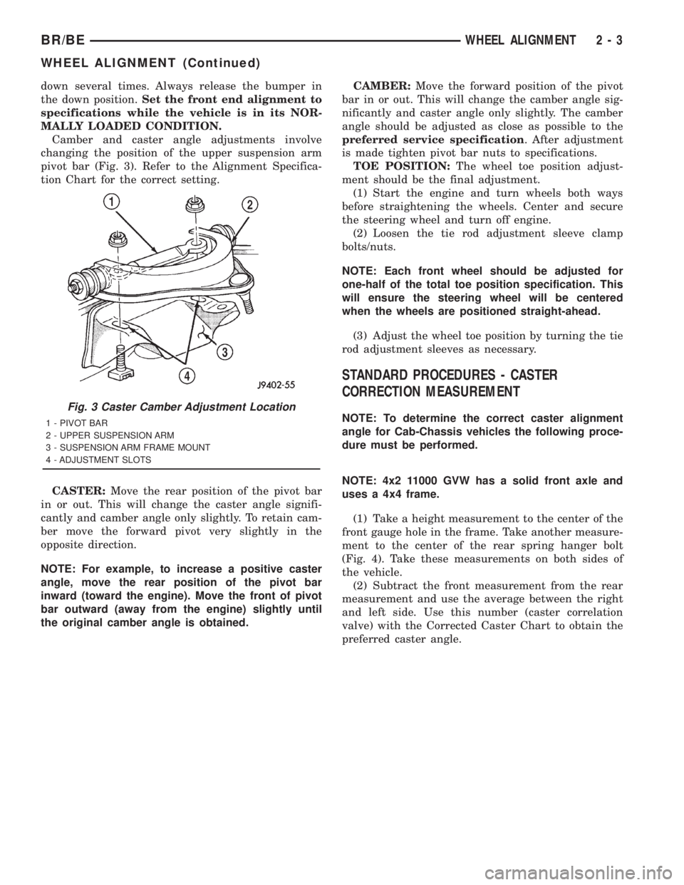
Camber and caster angle adjustments involve
changing the position of the upper suspension arm
pivot bar (Fig. 3). Refer to the Alignment Specifica-
tion Chart for the correct setting.
CASTER:Move the rear position of the pivot bar
in or out. This will change the caster angle signifi-
cantly and camber angle only slightly. To retain cam-
ber move the forward pivot very slightly in the
opposite direction.
NOTE: For example, to increase a positive caster
angle, move the rear position of the pivot bar
inward (toward the engine). Move the front of pivot
bar outward (away from the engine) slightly until
the original camber angle is obtained.CAMBER:Move the forward position of the pivot
bar in or out. This will change the camber angle sig-
nificantly and caster angle only slightly. The camber
angle should be adjusted as close as possible to the
preferred service specification. After adjustment
is made tighten pivot bar nuts to specifications.
TOE POSITION:The wheel toe position adjust-
ment should be the final adjustment.
(1) Start the engine and turn wheels both ways
before straightening the wheels. Center and secure
the steering wheel and turn off engine.
(2) Loosen the tie rod adjustment sleeve clamp
bolts/nuts.
NOTE: Each front wheel should be adjusted for
one-half of the total toe position specification. This
will ensure the steering wheel will be centered
when the wheels are positioned straight-ahead.
(3) Adjust the wheel toe position by turning the tie
rod adjustment sleeves as necessary.
STANDARD PROCEDURES - CASTER
CORRECTION MEASUREMENT
NOTE: To determine the correct caster alignment
angle for Cab-Chassis vehicles the following proce-
dure must be performed.
NOTE: 4x2 11000 GVW has a solid front axle and
uses a 4x4 frame.
(1) Take a height measurement to the center of the
front gauge hole in the frame. Take another measure-
ment to the center of the rear spring hanger bolt
(Fig. 4). Take these measurements on both sides of
the vehicle.
(2) Subtract the front measurement from the rear
measurement and use the average between the right
and left side. Use this number (caster correlation
valve) with the Corrected Caster Chart to obtain the
preferred caster angle.
Fig. 3 Caster Camber Adjustment Location
1 - PIVOT BAR
2 - UPPER SUSPENSION ARM
3 - SUSPENSION ARM FRAME MOUNT
4 - ADJUSTMENT SLOTS
BR/BEWHEEL ALIGNMENT 2 - 3
WHEEL ALIGNMENT (Continued)
Page 51 of 2889
CAUTION: Suspension components with rubber/ure-
thane bushings (except stabilizer bar) should betightened with the vehicle at normal ride height. It is
important to have the springs supporting the weight
of the vehicle when the fasteners are torqued. If
springs are not at their normal ride position, vehicle
ride comfort could be affected and premature bush-
ing wear may occur.
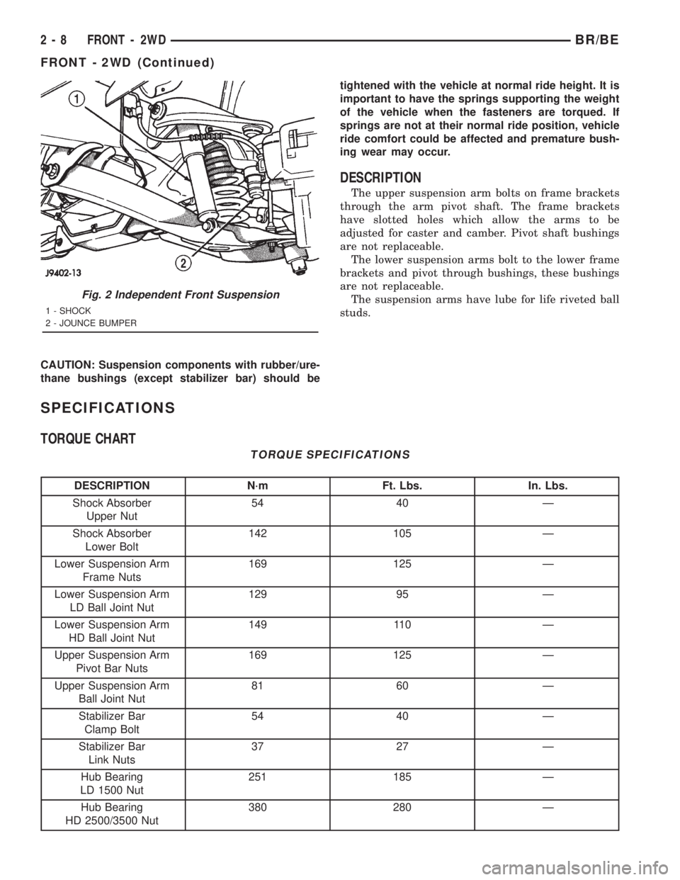
DESCRIPTION
The upper suspension arm bolts on frame brackets
through the arm pivot shaft. The frame brackets
have slotted holes which allow the arms to be
adjusted for caster and camber. Pivot shaft bushings
are not replaceable.
The lower suspension arms bolt to the lower frame
brackets and pivot through bushings, these bushings
are not replaceable.
The suspension arms have lube for life riveted ball
studs.
SPECIFICATIONS
TORQUE CHART
TORQUE SPECIFICATIONS
DESCRIPTION N´m Ft. Lbs. In. Lbs.
Shock Absorber
Upper Nut54 40 Ð
Shock Absorber
Lower Bolt142 105 Ð
Lower Suspension Arm
Frame Nuts169 125 Ð
Lower Suspension Arm
LD Ball Joint Nut129 95 Ð
Lower Suspension Arm
HD Ball Joint Nut149 110 Ð
Upper Suspension Arm
Pivot Bar Nuts169 125 Ð
Upper Suspension Arm
Ball Joint Nut81 60 Ð
Stabilizer Bar
Clamp Bolt54 40 Ð
Stabilizer Bar
Link Nuts37 27 Ð
Hub Bearing
LD 1500 Nut251 185 Ð
Hub Bearing
HD 2500/3500 Nut380 280 Ð
Fig. 2 Independent Front Suspension
1 - SHOCK
2 - JOUNCE BUMPER
2 - 8 FRONT - 2WDBR/BE
FRONT - 2WD (Continued)
Page 53 of 2889
OPERATION
The steering knuckles pivots between the upper
and lower ball joints. The steering linkage is
attached to the knuckles controls vehicle steering.
REMOVAL
(1) Raise and support the vehicle.
(2) Remove the wheel and tire assembly.
(3) Remove the brake caliper and rotor, (Refer to 5
- BRAKES/HYDRAULIC/MECHANICAL/DISC
BRAKE CALIPERS - REMOVAL).
(4) Remove the cotter pin and nut from the tie-rod
end. Remove the tie rod end from the knuckle with
Puller C-3894-A.
(5) Remove the cotter pins and nuts from the
upper and lower ball joints. Separate upper ball joint
from knuckle with remover MD-990635. Separate
lower ball joint with remover C-4150A and remove
knuckle.
INSTALLATION
(1) Position the knuckle on the ball joints and
install the ball joint nuts.
(2) Tighten the upper ball joint nut to 81 N´m (60
ft. lbs.) and install cotter pin.
(3) Tighten the lower ball joint nut to:
²LD: 129 N´m (95 ft. lbs.)
²HD: 149 N´m (110 ft. lbs.)
(3) Install the cotter pin.
(4) Install the tie rod end on the steering knuckle
and tighten the nut to 108 N´m (80 ft. lbs.). Install
cotter pin.
(5) Install the brake rotor and caliper, (Refer to 5 -
BRAKES/HYDRAULIC/MECHANICAL/DISC
BRAKE CALIPERS - INSTALLATION).
(6) Install wheel and tire assembly (Refer to 22 -
TIRES/WHEELS/WHEELS - STANDARD PROCE-
DURE).
(7) Remove support and lower vehicle.
LOWER BALL JOINT
DIAGNOSIS AND TESTING - LOWER BALL
JOINT
(1) Raise the front of the vehicle. Place safety floor
stands under both lower suspension arms as far out-
board as possible. Lower the vehicle to allow the
stands to support some or all of the vehicle weight.
NOTE: The upper suspension arms must not be in
maximum rebound position.
(2) Remove the tire and wheel assembly.
(3) Mount a dial indicator solidly under the lower
suspension arm.(4) Position indicator plunger against the bottom
of the steering knuckle lower ball joint boss.
NOTE: The dial Indicator plunger must be perpen-
dicular to the machined surface of the steering
knuckle lower ball joint boss.
(5) Position a pry bar over the top of the upper
suspension arm and under the pivot bar of the upper
suspension arm. Pry down on the upper suspension
arm and then zero the dial indicator.
(6) Reposition the pry bar under the upper suspen-
sion arm and on top of the frame rail. Pry up on the
upper suspension arm and record the dial indicator
reading.
(7) If the travel exceeds 0.8 mm (0.030 in.) replace
the suspension arm.
LOWER CONTROL ARM
REMOVAL
(1) Raise and support the vehicle.
(2) Remove the tire and wheel assembly.
(3) Remove the brake caliper assembly and rotor,
(Refer to 5 - BRAKES/HYDRAULIC/MECHANICAL/
ROTORS - REMOVAL).
(4) Remove the cotter pin and nut from the tie rod.
Remove the tie rod end from the steering knuckle
with Puller C-3894-A.
(5) Remove the stabilizer bar link from lower sus-
pension arm.
(6) Support the lower suspension arm outboard
end with jack. Place a jack under the arm in the
front of the shock mount.
(7) Remove the cotter pin and nut from the lower
ball joint. Separate the ball joint with Remover
C-4150A.
(8) Remove the lower shock bolt from the suspen-
sion arm.
(9) Lower the jack and suspension arm until
spring tension is relieved. Remove spring and rubber
isolator (Fig. 5).
(10) Remove bolts mounting suspension arm to
crossmember and remove arm.
INSTALLATION
(1) Position the suspension arm on the crossmem-
ber and install the bolts and nuts snug.
(2) Install the rubber isolator on top of the spring.
Position the spring into upper spring seat.
(3) Raise the lower suspension arm with a jack
and position the spring into the lower suspension
arm mount.
(4) Install the lower shock bolt and tighten to 142
N´m (105 ft. lbs.).
2 - 10 FRONT - 2WDBR/BE
KNUCKLE (Continued)
Page 54 of 2889
(5) Install the steering knuckle on the lower ball
joint. Install the lower ball joint nut and tighten to:
²LD: 129 N´m (95 ft. lbs.)
²HD: 136 N´m (110 ft. lbs.)
(5) Install the lower ball joint cotter pin.
(6) Install the stabilizer bar link on the lower sus-
pension arm. Install the grommet, retainer and nut
and tighten to 37 N´m (27 ft. lbs.).
(7) Install the tie rod end on the steering knuckle
and tighten nut to 108 N´m (80 ft. lbs.). Install cotter
pin.
(8) Install the brake rotor and caliper assembly,
(Refer to 5 - BRAKES/HYDRAULIC/MECHANICAL/
ROTORS - INSTALLATION).
(9) Install the tire and wheel assembly, (Refer to
22 - TIRES/WHEELS/WHEELS - STANDARD PRO-
CEDURE).
(10) Remove the support and lower the vehicle.
(11) Tighten the suspension arm crossmember
nuts to 169 N´m (125 ft. lbs.).
SHOCK
DESCRIPTION
The top of the shocks mounts on frame brackets
using grommets. The bottom of the shock is bolted to
the lower suspension arms.
OPERATION
The shock absorbers dampen jounce and rebound
of the vehicle over various road conditions.
DIAGNOSIS AND TESTING - SHOCK
A knocking or rattling noise from a shock absorber
may be caused by movement between mounting
bushings and metal brackets or attaching compo-
nents. These noises can usually be stopped by tight-
ening the attaching nuts. If the noise persists,
inspect for damaged and worn bushings, and attach-
ing components. Repair as necessary if any of these
conditions exist.
A squeaking noise from the shock absorber may be
caused by the hydraulic valving and may be intermit-
tent. This condition is not repairable and the shock
absorber must be replaced.
The shock absorbers are not refillable or adjust-
able. If a malfunction occurs, the shock absorber
must be replaced. To test a shock absorber, hold it in
an upright position and force the piston in and out of
the cylinder four or five times. The action throughout
each stroke should be smooth and even.
The shock absorber bushings do not require any
type of lubrication. Do not attempt to stop bushing
noise by lubricating them. Grease and mineral oil-
base lubricants will deteriorate the bushing.
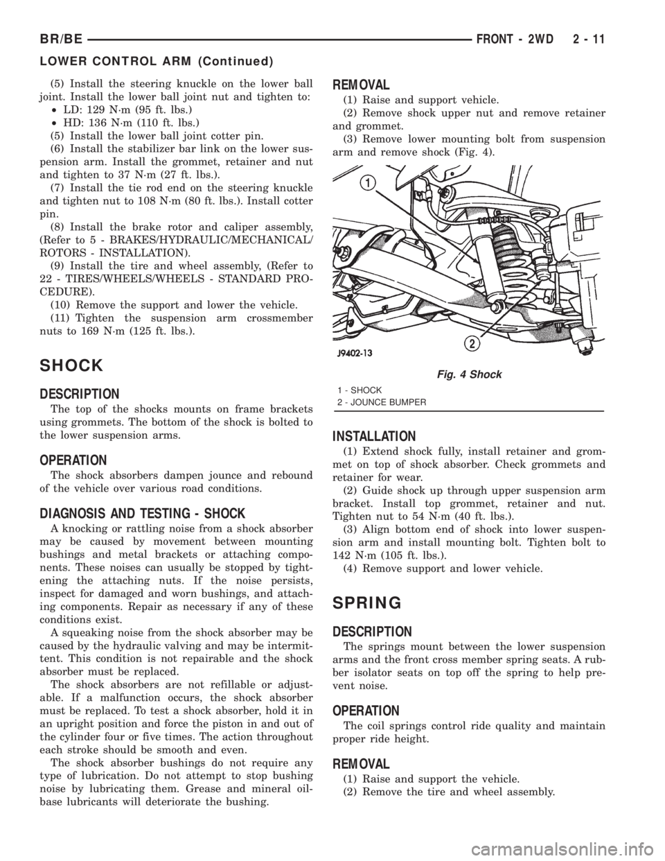
REMOVAL
(1) Raise and support vehicle.
(2) Remove shock upper nut and remove retainer
and grommet.
(3) Remove lower mounting bolt from suspension
arm and remove shock (Fig. 4).
INSTALLATION
(1) Extend shock fully, install retainer and grom-
met on top of shock absorber. Check grommets and
retainer for wear.
(2) Guide shock up through upper suspension arm
bracket. Install top grommet, retainer and nut.
Tighten nut to 54 N´m (40 ft. lbs.).
(3) Align bottom end of shock into lower suspen-
sion arm and install mounting bolt. Tighten bolt to
142 N´m (105 ft. lbs.).
(4) Remove support and lower vehicle.
SPRING
DESCRIPTION
The springs mount between the lower suspension
arms and the front cross member spring seats. A rub-
ber isolator seats on top off the spring to help pre-
vent noise.
OPERATION
The coil springs control ride quality and maintain
proper ride height.
REMOVAL
(1) Raise and support the vehicle.
(2) Remove the tire and wheel assembly.
Fig. 4 Shock
1 - SHOCK
2 - JOUNCE BUMPER
BR/BEFRONT - 2WD 2 - 11
LOWER CONTROL ARM (Continued)
Page 55 of 2889
(3) Remove the brake caliper assembly and rotor,
(Refer to 5 - BRAKES/HYDRAULIC/MECHANICAL/
ROTORS - REMOVAL).
(4) Remove the cotter pin and nut from the tie rod.
Remove the tie rod end from the steering knuckle
with Puller C-3894-A.
(5) Remove the stabilizer bar link from the lower
suspension arm.
(6) Support the lower suspension arm outboard
end with a jack. Place a jack under the arm in front
of the shock mount.
(7) Remove the cotter pin and nut from the lower
ball joint. Separate the ball joint with Remover
C-4150A.
(8) Remove the lower shock bolt from the suspen-
sion arm.
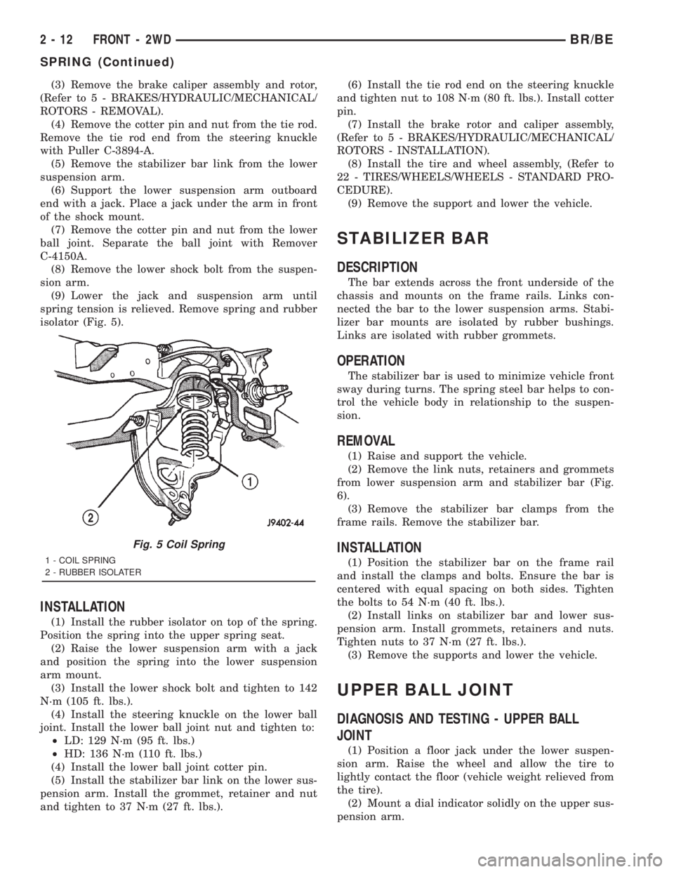
(9) Lower the jack and suspension arm until
spring tension is relieved. Remove spring and rubber
isolator (Fig. 5).
INSTALLATION
(1) Install the rubber isolator on top of the spring.
Position the spring into the upper spring seat.
(2) Raise the lower suspension arm with a jack
and position the spring into the lower suspension
arm mount.
(3) Install the lower shock bolt and tighten to 142
N´m (105 ft. lbs.).
(4) Install the steering knuckle on the lower ball
joint. Install the lower ball joint nut and tighten to:
²LD: 129 N´m (95 ft. lbs.)
²HD: 136 N´m (110 ft. lbs.)
(4) Install the lower ball joint cotter pin.
(5) Install the stabilizer bar link on the lower sus-
pension arm. Install the grommet, retainer and nut
and tighten to 37 N´m (27 ft. lbs.).(6) Install the tie rod end on the steering knuckle
and tighten nut to 108 N´m (80 ft. lbs.). Install cotter
pin.
(7) Install the brake rotor and caliper assembly,
(Refer to 5 - BRAKES/HYDRAULIC/MECHANICAL/
ROTORS - INSTALLATION).
(8) Install the tire and wheel assembly, (Refer to
22 - TIRES/WHEELS/WHEELS - STANDARD PRO-
CEDURE).
(9) Remove the support and lower the vehicle.
STABILIZER BAR
DESCRIPTION
The bar extends across the front underside of the
chassis and mounts on the frame rails. Links con-
nected the bar to the lower suspension arms. Stabi-
lizer bar mounts are isolated by rubber bushings.
Links are isolated with rubber grommets.
OPERATION
The stabilizer bar is used to minimize vehicle front
sway during turns. The spring steel bar helps to con-
trol the vehicle body in relationship to the suspen-
sion.
REMOVAL
(1) Raise and support the vehicle.
(2) Remove the link nuts, retainers and grommets
from lower suspension arm and stabilizer bar (Fig.
6).
(3) Remove the stabilizer bar clamps from the
frame rails. Remove the stabilizer bar.
INSTALLATION
(1) Position the stabilizer bar on the frame rail
and install the clamps and bolts. Ensure the bar is
centered with equal spacing on both sides. Tighten
the bolts to 54 N´m (40 ft. lbs.).
(2) Install links on stabilizer bar and lower sus-
pension arm. Install grommets, retainers and nuts.
Tighten nuts to 37 N´m (27 ft. lbs.).
(3) Remove the supports and lower the vehicle.
UPPER BALL JOINT
DIAGNOSIS AND TESTING - UPPER BALL
JOINT
(1) Position a floor jack under the lower suspen-
sion arm. Raise the wheel and allow the tire to
lightly contact the floor (vehicle weight relieved from
the tire).
(2) Mount a dial indicator solidly on the upper sus-
pension arm.
Fig. 5 Coil Spring
1 - COIL SPRING
2 - RUBBER ISOLATER
2 - 12 FRONT - 2WDBR/BE
SPRING (Continued)