lock DODGE RAM 2001 Service Repair Manual
[x] Cancel search | Manufacturer: DODGE, Model Year: 2001, Model line: RAM, Model: DODGE RAM 2001Pages: 2889, PDF Size: 68.07 MB
Page 36 of 2889
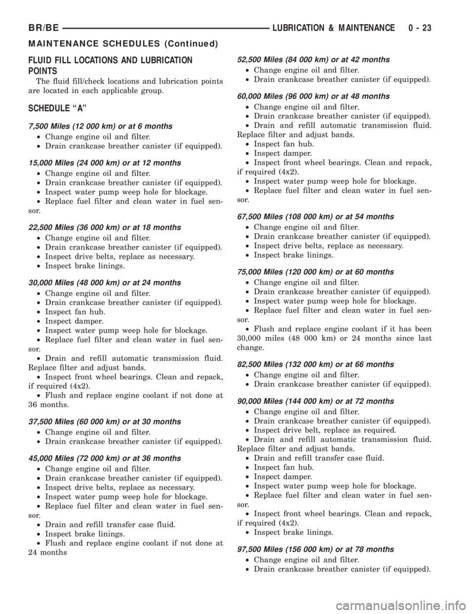
FLUID FILL LOCATIONS AND LUBRICATION
POINTS
The fluid fill/check locations and lubrication points
are located in each applicable group.
SCHEDULE ªAº
7,500 Miles (12 000 km) or at 6 months
²Change engine oil and filter.
²Drain crankcase breather canister (if equipped).
15,000 Miles (24 000 km) or at 12 months
²Change engine oil and filter.
²Drain crankcase breather canister (if equipped).
²Inspect water pump weep hole for blockage.
²Replace fuel filter and clean water in fuel sen-
sor.
22,500 Miles (36 000 km) or at 18 months
²Change engine oil and filter.
²Drain crankcase breather canister (if equipped).
²Inspect drive belts, replace as necessary.
²Inspect brake linings.
30,000 Miles (48 000 km) or at 24 months
²Change engine oil and filter.
²Drain crankcase breather canister (if equipped).
²Inspect fan hub.
²Inspect damper.
²Inspect water pump weep hole for blockage.
²Replace fuel filter and clean water in fuel sen-
sor.
²Drain and refill automatic transmission fluid.
Replace filter and adjust bands.
²Inspect front wheel bearings. Clean and repack,
if required (4x2).
²Flush and replace engine coolant if not done at
36 months.
37,500 Miles (60 000 km) or at 30 months
²Change engine oil and filter.
²Drain crankcase breather canister (if equipped).
45,000 Miles (72 000 km) or at 36 months
²Change engine oil and filter.
²Drain crankcase breather canister (if equipped).
²Inspect drive belts, replace as necessary.
²Inspect water pump weep hole for blockage.
²Replace fuel filter and clean water in fuel sen-
sor.
²Drain and refill transfer case fluid.
²Inspect brake linings.
²Flush and replace engine coolant if not done at
24 months
52,500 Miles (84 000 km) or at 42 months
²Change engine oil and filter.
²Drain crankcase breather canister (if equipped).
60,000 Miles (96 000 km) or at 48 months
²Change engine oil and filter.
²Drain crankcase breather canister (if equipped).
²Drain and refill automatic transmission fluid.
Replace filter and adjust bands.
²Inspect fan hub.
²Inspect damper.
²Inspect front wheel bearings. Clean and repack,
if required (4x2).
²Inspect water pump weep hole for blockage.
²Replace fuel filter and clean water in fuel sen-
sor.
67,500 Miles (108 000 km) or at 54 months
²Change engine oil and filter.
²Drain crankcase breather canister (if equipped).
²Inspect drive belts, replace as necessary.
²Inspect brake linings.
75,000 Miles (120 000 km) or at 60 months
²Change engine oil and filter.
²Drain crankcase breather canister (if equipped).
²Inspect water pump weep hole for blockage.
²Replace fuel filter and clean water in fuel sen-
sor.
²Flush and replace engine coolant if it has been
30,000 miles (48 000 km) or 24 months since last
change.
82,500 Miles (132 000 km) or at 66 months
²Change engine oil and filter.
²Drain crankcase breather canister (if equipped).
90,000 Miles (144 000 km) or at 72 months
²Change engine oil and filter.
²Drain crankcase breather canister (if equipped).
²Inspect drive belt, replace as required.
²Drain and refill automatic transmission fluid.
Replace filter and adjust bands.
²Drain and refill transfer case fluid.
²Inspect fan hub.
²Inspect damper.
²Inspect water pump weep hole for blockage.
²Replace fuel filter and clean water in fuel sen-
sor.
²Inspect front wheel bearings. Clean and repack,
if required (4x2).
²Inspect brake linings.
97,500 Miles (156 000 km) or at 78 months
²Change engine oil and filter.
²Drain crankcase breather canister (if equipped).
BR/BELUBRICATION & MAINTENANCE 0 - 23
MAINTENANCE SCHEDULES (Continued)
Page 37 of 2889
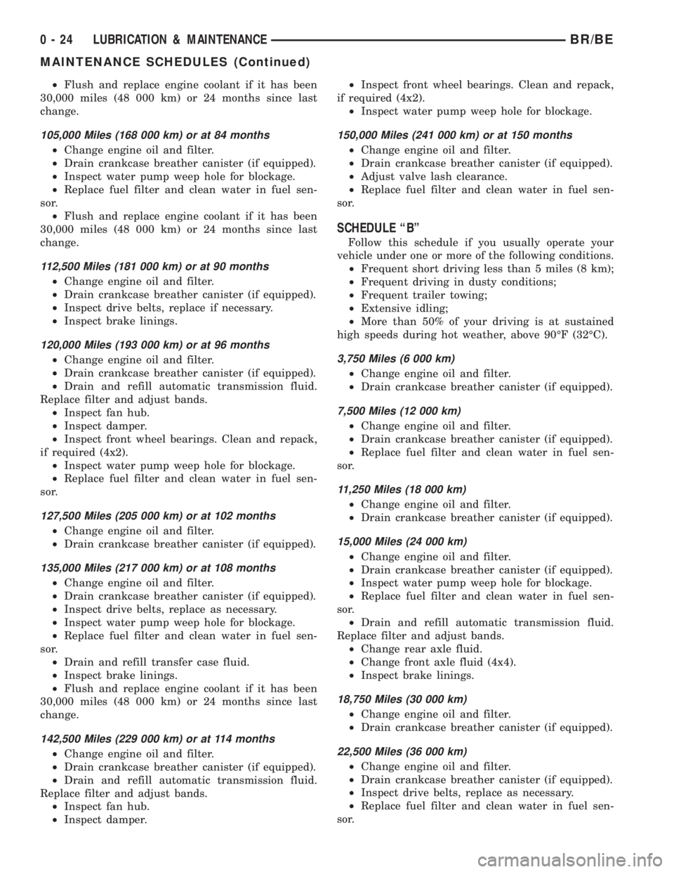
²Flush and replace engine coolant if it has been
30,000 miles (48 000 km) or 24 months since last
change.
105,000 Miles (168 000 km) or at 84 months
²Change engine oil and filter.
²Drain crankcase breather canister (if equipped).
²Inspect water pump weep hole for blockage.
²Replace fuel filter and clean water in fuel sen-
sor.
²Flush and replace engine coolant if it has been
30,000 miles (48 000 km) or 24 months since last
change.
112,500 Miles (181 000 km) or at 90 months
²Change engine oil and filter.
²Drain crankcase breather canister (if equipped).
²Inspect drive belts, replace if necessary.
²Inspect brake linings.
120,000 Miles (193 000 km) or at 96 months
²Change engine oil and filter.
²Drain crankcase breather canister (if equipped).
²Drain and refill automatic transmission fluid.
Replace filter and adjust bands.
²Inspect fan hub.
²Inspect damper.
²Inspect front wheel bearings. Clean and repack,
if required (4x2).
²Inspect water pump weep hole for blockage.
²Replace fuel filter and clean water in fuel sen-
sor.
127,500 Miles (205 000 km) or at 102 months
²Change engine oil and filter.
²Drain crankcase breather canister (if equipped).
135,000 Miles (217 000 km) or at 108 months
²Change engine oil and filter.
²Drain crankcase breather canister (if equipped).
²Inspect drive belts, replace as necessary.
²Inspect water pump weep hole for blockage.
²Replace fuel filter and clean water in fuel sen-
sor.
²Drain and refill transfer case fluid.
²Inspect brake linings.
²Flush and replace engine coolant if it has been
30,000 miles (48 000 km) or 24 months since last
change.
142,500 Miles (229 000 km) or at 114 months
²Change engine oil and filter.
²Drain crankcase breather canister (if equipped).
²Drain and refill automatic transmission fluid.
Replace filter and adjust bands.
²Inspect fan hub.
²Inspect damper.²Inspect front wheel bearings. Clean and repack,
if required (4x2).
²Inspect water pump weep hole for blockage.
150,000 Miles (241 000 km) or at 150 months
²Change engine oil and filter.
²Drain crankcase breather canister (if equipped).
²Adjust valve lash clearance.
²Replace fuel filter and clean water in fuel sen-
sor.
SCHEDULE ªBº
Follow this schedule if you usually operate your
vehicle under one or more of the following conditions.
²Frequent short driving less than 5 miles (8 km);
²Frequent driving in dusty conditions;
²Frequent trailer towing;
²Extensive idling;
²More than 50% of your driving is at sustained
high speeds during hot weather, above 90ÉF (32ÉC).
3,750 Miles (6 000 km)
²Change engine oil and filter.
²Drain crankcase breather canister (if equipped).
7,500 Miles (12 000 km)
²Change engine oil and filter.
²Drain crankcase breather canister (if equipped).
²Replace fuel filter and clean water in fuel sen-
sor.
11,250 Miles (18 000 km)
²Change engine oil and filter.
²Drain crankcase breather canister (if equipped).
15,000 Miles (24 000 km)
²Change engine oil and filter.
²Drain crankcase breather canister (if equipped).
²Inspect water pump weep hole for blockage.
²Replace fuel filter and clean water in fuel sen-
sor.
²Drain and refill automatic transmission fluid.
Replace filter and adjust bands.
²Change rear axle fluid.
²Change front axle fluid (4x4).
²Inspect brake linings.
18,750 Miles (30 000 km)
²Change engine oil and filter.
²Drain crankcase breather canister (if equipped).
22,500 Miles (36 000 km)
²Change engine oil and filter.
²Drain crankcase breather canister (if equipped).
²Inspect drive belts, replace as necessary.
²Replace fuel filter and clean water in fuel sen-
sor.
0 - 24 LUBRICATION & MAINTENANCEBR/BE
MAINTENANCE SCHEDULES (Continued)
Page 38 of 2889
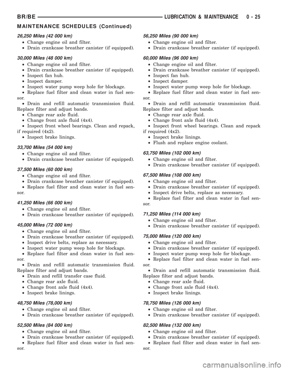
26,250 Miles (42 000 km)
²Change engine oil and filter.
²Drain crankcase breather canister (if equipped).
30,000 Miles (48 000 km)
²Change engine oil and filter.
²Drain crankcase breather canister (if equipped).
²Inspect fan hub.
²Inspect damper.
²Inspect water pump weep hole for blockage.
²Replace fuel filter and clean water in fuel sen-
sor.
²Drain and refill automatic transmission fluid.
Replace filter and adjust bands.
²Change rear axle fluid.
²Change front axle fluid (4x4).
²Inspect front wheel bearings. Clean and repack,
if required (4x2).
²Inspect brake linings.
33,700 Miles (54 000 km)
²Change engine oil and filter.
²Drain crankcase breather canister (if equipped).
37,500 Miles (60 000 km)
²Change engine oil and filter.
²Drain crankcase breather canister (if equipped).
²Replace fuel filter and clean water in fuel sen-
sor.
41,250 Miles (66 000 km)
²Change engine oil and filter.
²Drain crankcase breather canister (if equipped).
45,000 Miles (72 000 km)
²Change engine oil and filter.
²Drain crankcase breather canister (if equipped).
²Inspect drive belts, replace as necessary.
²Inspect water pump weep hole for blockage.
²Replace fuel filter and clean water in fuel sen-
sor.
²Drain and refill automatic transmission fluid.
Replace filter and adjust bands.
²Drain and refill transfer case fluid.
²Change rear axle fluid.
²Change front axle fluid (4x4).
²Inspect brake linings.
48,750 Miles (78,000 km)
²Change engine oil and filter.
²Drain crankcase breather canister (if equipped).
52,500 Miles (84 000 km)
²Change engine oil and filter.
²Drain crankcase breather canister (if equipped).
²Replace fuel filter and clean water in fuel sen-
sor.
56,250 Miles (90 000 km)
²Change engine oil and filter.
²Drain crankcase breather canister (if equipped).
60,000 Miles (96 000 km)
²Change engine oil and filter.
²Drain crankcase breather canister (if equipped).
²Inspect fan hub.
²Inspect damper.
²Inspect water pump weep hole for blockage.
²Replace fuel filter and clean water in fuel sen-
sor.
²Drain and refill automatic transmission fluid.
Replace filter and adjust bands.
²Change rear axle fluid.
²Change front axle fluid (4x4).
²Inspect front wheel bearings. Clean and repack
if required (4x2).
²Inspect brake linings.
²Flush and replace engine coolant.
63,750 Miles (102 000 km)
²Change engine oil and filter.
²Drain crankcase breather canister (if equipped).
67,500 Miles (108 000 km)
²Change engine oil and filter.
²Drain crankcase breather canister (if equipped).
²Inspect drive belts, replace as necessary.
²Replace fuel filter and clean water in fuel sen-
sor.
71,250 Miles (114 000 km)
²Change engine oil and filter.
²Drain crankcase breather canister (if equipped).
75,000 Miles (120 000 km)
²Change engine oil and filter.
²Drain crankcase breather canister (if equipped).
²Inspect water pump weep hole for blockage.
²Replace fuel filter and clean water in fuel sen-
sor.
²Drain and refill automatic transmission fluid.
Replace filter and adjust bands.
²Change rear axle fluid.
²Change front axle fluid (4x4).
²Inspect brake linings.
78,750 Miles (126 000 km)
²Change engine oil and filter.
²Drain crankcase breather canister (if equipped).
82,500 Miles (132 000 km)
²Change engine oil and filter.
²Drain crankcase breather canister (if equipped).
²Replace fuel filter and clean water in fuel sen-
sor.
BR/BELUBRICATION & MAINTENANCE 0 - 25
MAINTENANCE SCHEDULES (Continued)
Page 39 of 2889
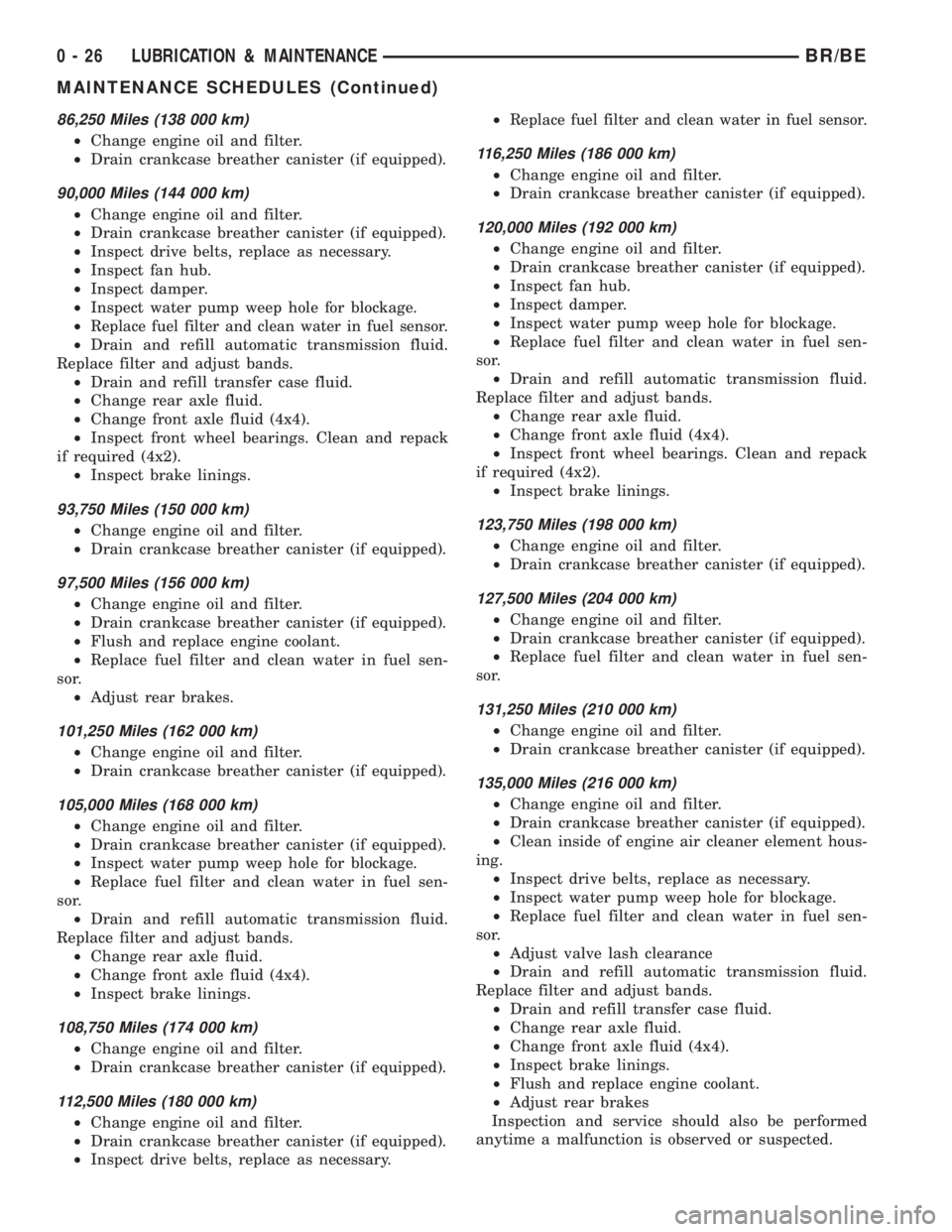
86,250 Miles (138 000 km)
²Change engine oil and filter.
²Drain crankcase breather canister (if equipped).
90,000 Miles (144 000 km)
²Change engine oil and filter.
²Drain crankcase breather canister (if equipped).
²Inspect drive belts, replace as necessary.
²Inspect fan hub.
²Inspect damper.
²Inspect water pump weep hole for blockage.
²
Replace fuel filter and clean water in fuel sensor.
²Drain and refill automatic transmission fluid.
Replace filter and adjust bands.
²Drain and refill transfer case fluid.
²Change rear axle fluid.
²Change front axle fluid (4x4).
²Inspect front wheel bearings. Clean and repack
if required (4x2).
²Inspect brake linings.
93,750 Miles (150 000 km)
²Change engine oil and filter.
²Drain crankcase breather canister (if equipped).
97,500 Miles (156 000 km)
²Change engine oil and filter.
²Drain crankcase breather canister (if equipped).
²Flush and replace engine coolant.
²Replace fuel filter and clean water in fuel sen-
sor.
²Adjust rear brakes.
101,250 Miles (162 000 km)
²Change engine oil and filter.
²Drain crankcase breather canister (if equipped).
105,000 Miles (168 000 km)
²Change engine oil and filter.
²Drain crankcase breather canister (if equipped).
²Inspect water pump weep hole for blockage.
²Replace fuel filter and clean water in fuel sen-
sor.
²Drain and refill automatic transmission fluid.
Replace filter and adjust bands.
²Change rear axle fluid.
²Change front axle fluid (4x4).
²Inspect brake linings.
108,750 Miles (174 000 km)
²Change engine oil and filter.
²Drain crankcase breather canister (if equipped).
112,500 Miles (180 000 km)
²Change engine oil and filter.
²Drain crankcase breather canister (if equipped).
²Inspect drive belts, replace as necessary.²
Replace fuel filter and clean water in fuel sensor.
116,250 Miles (186 000 km)
²Change engine oil and filter.
²Drain crankcase breather canister (if equipped).
120,000 Miles (192 000 km)
²Change engine oil and filter.
²Drain crankcase breather canister (if equipped).
²Inspect fan hub.
²Inspect damper.
²Inspect water pump weep hole for blockage.
²Replace fuel filter and clean water in fuel sen-
sor.
²Drain and refill automatic transmission fluid.
Replace filter and adjust bands.
²Change rear axle fluid.
²Change front axle fluid (4x4).
²Inspect front wheel bearings. Clean and repack
if required (4x2).
²Inspect brake linings.
123,750 Miles (198 000 km)
²Change engine oil and filter.
²Drain crankcase breather canister (if equipped).
127,500 Miles (204 000 km)
²Change engine oil and filter.
²Drain crankcase breather canister (if equipped).
²Replace fuel filter and clean water in fuel sen-
sor.
131,250 Miles (210 000 km)
²Change engine oil and filter.
²Drain crankcase breather canister (if equipped).
135,000 Miles (216 000 km)
²Change engine oil and filter.
²Drain crankcase breather canister (if equipped).
²Clean inside of engine air cleaner element hous-
ing.
²Inspect drive belts, replace as necessary.
²Inspect water pump weep hole for blockage.
²Replace fuel filter and clean water in fuel sen-
sor.
²Adjust valve lash clearance
²Drain and refill automatic transmission fluid.
Replace filter and adjust bands.
²Drain and refill transfer case fluid.
²Change rear axle fluid.
²Change front axle fluid (4x4).
²Inspect brake linings.
²Flush and replace engine coolant.
²Adjust rear brakes
Inspection and service should also be performed
anytime a malfunction is observed or suspected.
0 - 26 LUBRICATION & MAINTENANCEBR/BE
MAINTENANCE SCHEDULES (Continued)
Page 43 of 2889
²Do not tow a vehicle in a manner that could
jeopardize the safety of the operator, pedestrians or
other motorists.
²Do not attach tow chains, T-hooks, J-hooks, or a
tow sling to a bumper, steering linkage, drive shafts
or a non-reinforced frame hole.
²Do not tow a heavily loaded vehicle. Damage to
the cab, cargo box or frame may result. Use a flatbed
device to transport a loaded vehicle.
GROUND CLEARANCE
CAUTION: If vehicle is towed with wheels removed,
install lug nuts to retain brake drums or rotors.
A towed vehicle should be raised until lifted wheels
are a minimum 100 mm (4 in) from the ground. Be
sure there is adequate ground clearance at the oppo-
site end of the vehicle, especially when towing over
rough terrain or steep rises in the road. If necessary,
remove the wheels from the lifted end of the vehicle
and lower the vehicle closer to the ground, to
increase the ground clearance at the opposite end of
the vehicle. Install lug nuts on wheel attaching studs
to retain brake drums or rotors.
RAMP ANGLE
If a vehicle with flat-bed towing equipment is used,
the approach ramp angle should not exceed 15
degrees.
TOWING WHEN KEYS ARE NOT AVAILABLE
When the vehicle is locked and keys are not avail-
able, use a flat bed hauler. A Wheel-lift or Sling-type
device can be used on 4WD vehicles providedall the
wheels are lifted off the ground using tow dol-
lies.
FOUR-WHEEL-DRIVE VEHICLE TOWING
Chrysler Corporation recommends that a vehicle be
transported on a flat-bed device. A Wheel-lift or
Sling-type device can be used providedall the
wheels are lifted off the ground using tow dol-
lies.
WARNING: WHEN TOWING A DISABLED VEHICLE
AND THE DRIVE WHEELS ARE SECURED IN A
WHEEL LIFT OR TOW DOLLIES, ENSURE THE
TRANSMISSION IS IN THE PARK POSITION (AUTO-
MATIC TRANSMISSION) OR A FORWARD DRIVE
GEAR (MANUAL TRANSMISSION).
CAUTION: Many vehicles are equipped with air
dams, spoilers, and/or ground effect panels. To
avoid component damage, a wheel-lift towing vehi-
cle or a flat-bed hauling vehicle is recommended.
0 - 30 LUBRICATION & MAINTENANCEBR/BE
TOWING (Continued)
Page 52 of 2889
SPECIAL TOOLS
INDEPENDENT FRONT SUSPENSION
HUB / BEARING
REMOVAL
(1) Raise and support the vehicle.
(2) Remove the wheel and tire assembly.
(3) Remove the caliper adapter bolts from the
steering knuckle and remove caliper adapter assem-
bly (Refer to 5 - BRAKES/HYDRAULIC/MECHANI-
CAL/DISC BRAKE CALIPERS - REMOVAL).
NOTE: Do not allow brake hose to support caliper
adapter assembly.
(4) Remove the rotor from the hub/bearing wheel
studs.
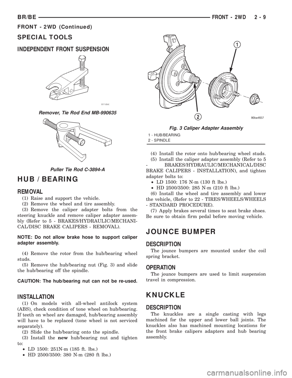
(5) Remove the hub/bearing nut (Fig. 3) and slide
the hub/bearing off the spindle.
CAUTION: The hub/bearing nut can not be re-used.
INSTALLATION
(1) On models with all-wheel antilock system
(ABS), check condition of tone wheel on hub/bearing.
If teeth on wheel are damaged, hub/bearing assembly
will have to be replaced (tone wheel is not serviced
separately).
(2) Slide the hub/bearing onto the spindle.
(3) Install thenewhub/bearing nut and tighten
to:
²LD 1500: 251N´m (185 ft. lbs.)
²HD 2500/3500: 380 N´m (280 ft lbs.)(4) Install the rotor onto hub/bearing wheel studs.
(5) Install the caliper adapter assembly (Refer to 5
- BRAKES/HYDRAULIC/MECHANICAL/DISC
BRAKE CALIPERS - INSTALLATION), and tighten
adapter bolts to:
²LD 1500: 176 N´m (130 ft lbs.)
²HD 2500/3500: 285 N´m (210 ft lbs.)
(6) Install the wheel and tire assembly and lower
the vehicle, (Refer to 22 - TIRES/WHEELS/WHEELS
- STANDARD PROCEDURE).
(7) Apply brakes several times to seat brake shoes.
Be sure to obtain firm pedal before moving vehicle.
JOUNCE BUMPER
DESCRIPTION
The jounce bumpers are mounted under the coil
spring bracket.
OPERATION
The jounce bumpers are used to limit suspension
travel in compression.
KNUCKLE
DESCRIPTION
The knuckles are a single casting with legs
machined for the upper and lower ball joints. The
knuckles also has machined mounting locations for
the front brake calipers adapters and hub bearing
assembly.
Remover, Tie Rod End MB-990635
Puller Tie Rod C-3894-A
Fig. 3 Caliper Adapter Assembly
1 - HUB/BEARING
2 - SPINDLE
BR/BEFRONT - 2WD 2 - 9
FRONT - 2WD (Continued)
Page 91 of 2889
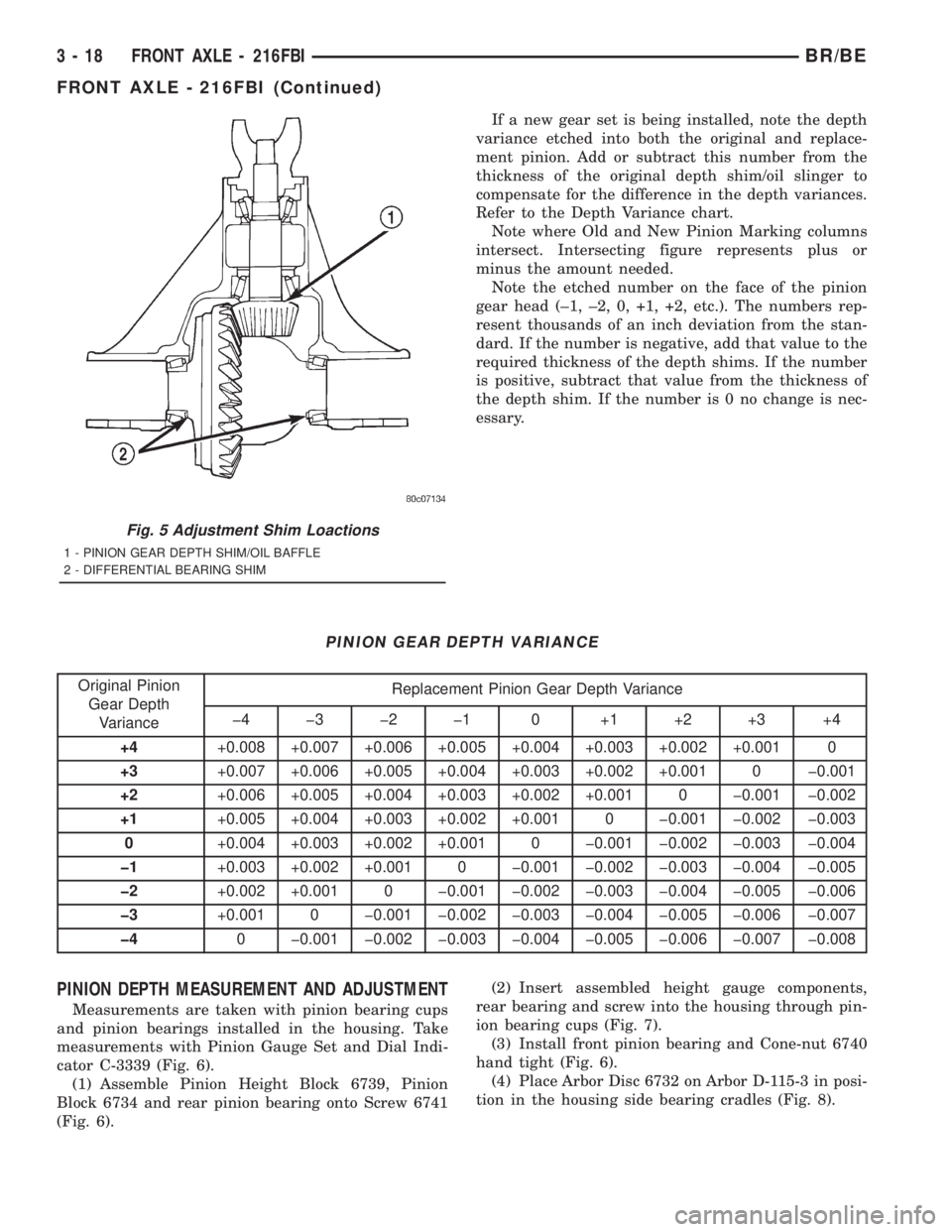
If a new gear set is being installed, note the depth
variance etched into both the original and replace-
ment pinion. Add or subtract this number from the
thickness of the original depth shim/oil slinger to
compensate for the difference in the depth variances.
Refer to the Depth Variance chart.
Note where Old and New Pinion Marking columns
intersect. Intersecting figure represents plus or
minus the amount needed.
Note the etched number on the face of the pinion
gear head (±1, ±2, 0, +1, +2, etc.). The numbers rep-
resent thousands of an inch deviation from the stan-
dard. If the number is negative, add that value to the
required thickness of the depth shims. If the number
is positive, subtract that value from the thickness of
the depth shim. If the number is 0 no change is nec-
essary.
PINION GEAR DEPTH VARIANCE
Original Pinion
Gear Depth
VarianceReplacement Pinion Gear Depth Variance
þ4 þ3 þ2 þ1 0 +1 +2 +3 +4
+4+0.008 +0.007 +0.006 +0.005 +0.004 +0.003 +0.002 +0.001 0
+3+0.007 +0.006 +0.005 +0.004 +0.003 +0.002 +0.001 0 þ0.001
+2+0.006 +0.005 +0.004 +0.003 +0.002 +0.001 0 þ0.001 þ0.002
+1+0.005 +0.004 +0.003 +0.002 +0.001 0 þ0.001 þ0.002 þ0.003
0+0.004 +0.003 +0.002 +0.001 0 þ0.001 þ0.002 þ0.003 þ0.004
þ1+0.003 +0.002 +0.001 0 þ0.001 þ0.002 þ0.003 þ0.004 þ0.005
þ2+0.002 +0.001 0 þ0.001 þ0.002 þ0.003 þ0.004 þ0.005 þ0.006
þ3+0.001 0 þ0.001 þ0.002 þ0.003 þ0.004 þ0.005 þ0.006 þ0.007
þ40 þ0.001 þ0.002 þ0.003 þ0.004 þ0.005 þ0.006 þ0.007 þ0.008
PINION DEPTH MEASUREMENT AND ADJUSTMENT
Measurements are taken with pinion bearing cups
and pinion bearings installed in the housing. Take
measurements with Pinion Gauge Set and Dial Indi-
cator C-3339 (Fig. 6).
(1) Assemble Pinion Height Block 6739, Pinion
Block 6734 and rear pinion bearing onto Screw 6741
(Fig. 6).(2) Insert assembled height gauge components,
rear bearing and screw into the housing through pin-
ion bearing cups (Fig. 7).
(3) Install front pinion bearing and Cone-nut 6740
hand tight (Fig. 6).
(4) Place Arbor Disc 6732 on Arbor D-115-3 in posi-
tion in the housing side bearing cradles (Fig. 8).
Fig. 5 Adjustment Shim Loactions
1 - PINION GEAR DEPTH SHIM/OIL BAFFLE
2 - DIFFERENTIAL BEARING SHIM
3 - 18 FRONT AXLE - 216FBIBR/BE
FRONT AXLE - 216FBI (Continued)
Page 92 of 2889
NOTE: Arbor Discs 6732 has different step diame-
ters to fit other axles. Choose proper step for axle
being serviced.(5) Install differential bearing caps on arbor discs
and snug the bearing cap bolts. Then cross tighten
cap bolts to 108 N´m (80 ft. lbs.).
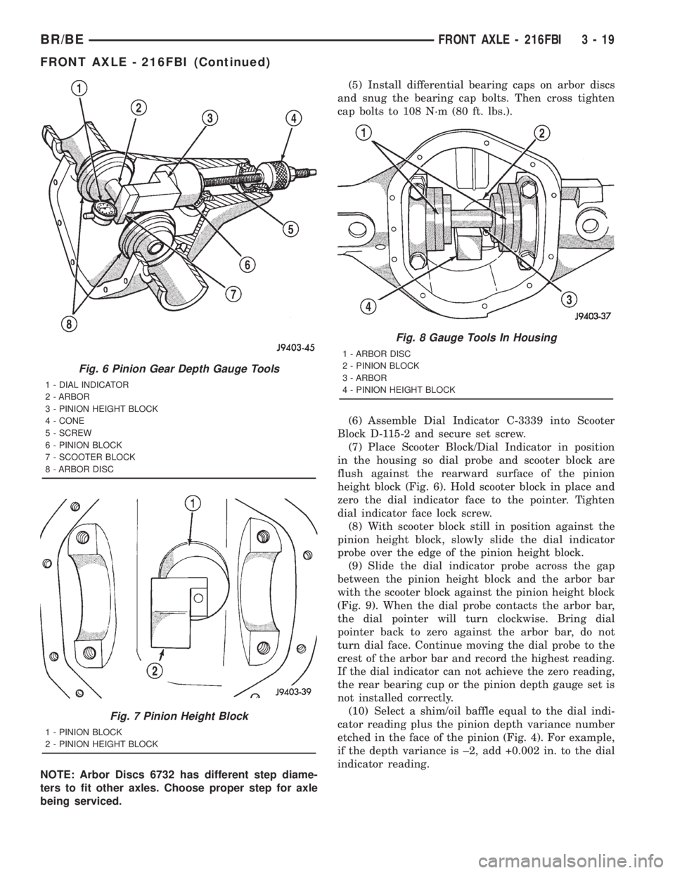
(6) Assemble Dial Indicator C-3339 into Scooter
Block D-115-2 and secure set screw.
(7) Place Scooter Block/Dial Indicator in position
in the housing so dial probe and scooter block are
flush against the rearward surface of the pinion
height block (Fig. 6). Hold scooter block in place and
zero the dial indicator face to the pointer. Tighten
dial indicator face lock screw.
(8) With scooter block still in position against the
pinion height block, slowly slide the dial indicator
probe over the edge of the pinion height block.
(9) Slide the dial indicator probe across the gap
between the pinion height block and the arbor bar
with the scooter block against the pinion height block
(Fig. 9). When the dial probe contacts the arbor bar,
the dial pointer will turn clockwise. Bring dial
pointer back to zero against the arbor bar, do not
turn dial face. Continue moving the dial probe to the
crest of the arbor bar and record the highest reading.
If the dial indicator can not achieve the zero reading,
the rear bearing cup or the pinion depth gauge set is
not installed correctly.
(10) Select a shim/oil baffle equal to the dial indi-
cator reading plus the pinion depth variance number
etched in the face of the pinion (Fig. 4). For example,
if the depth variance is ±2, add +0.002 in. to the dial
indicator reading.
Fig. 6 Pinion Gear Depth Gauge Tools
1 - DIAL INDICATOR
2 - ARBOR
3 - PINION HEIGHT BLOCK
4 - CONE
5 - SCREW
6 - PINION BLOCK
7 - SCOOTER BLOCK
8 - ARBOR DISC
Fig. 7 Pinion Height Block
1 - PINION BLOCK
2 - PINION HEIGHT BLOCK
Fig. 8 Gauge Tools In Housing
1 - ARBOR DISC
2 - PINION BLOCK
3 - ARBOR
4 - PINION HEIGHT BLOCK
BR/BEFRONT AXLE - 216FBI 3 - 19
FRONT AXLE - 216FBI (Continued)
Page 93 of 2889
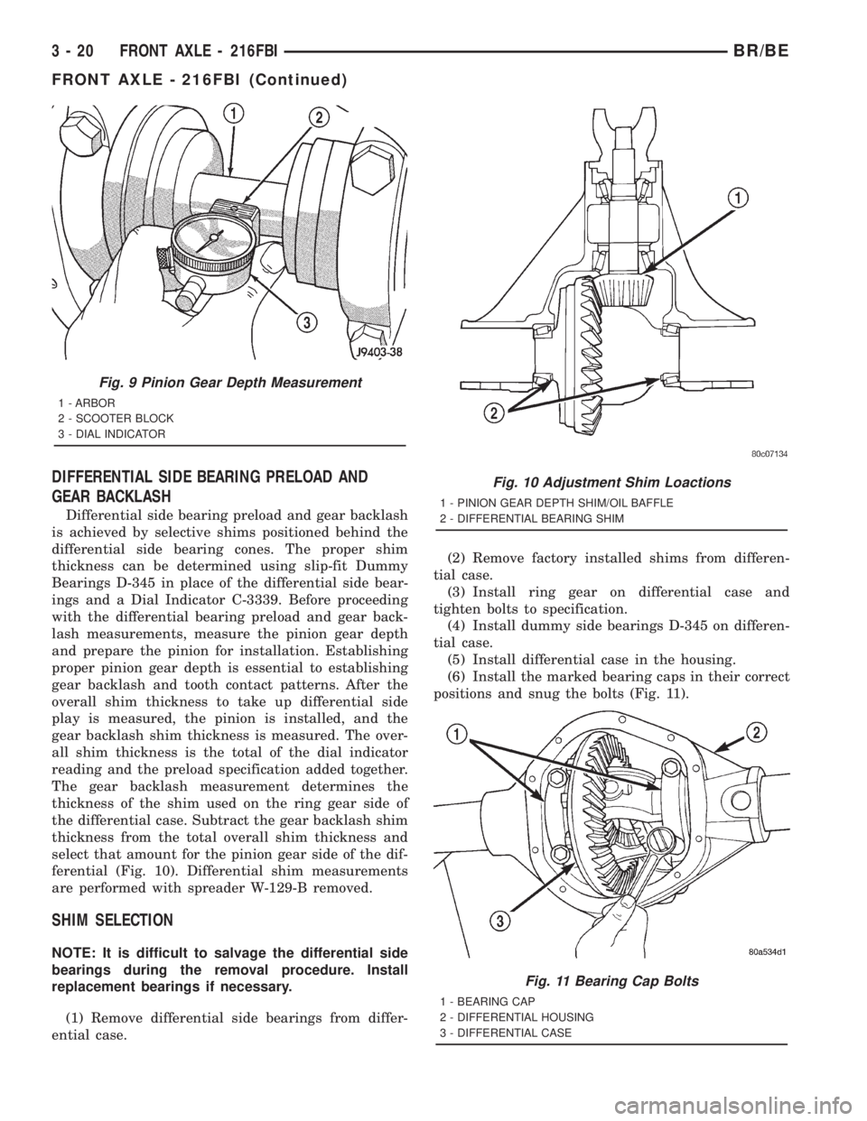
DIFFERENTIAL SIDE BEARING PRELOAD AND
GEAR BACKLASH
Differential side bearing preload and gear backlash
is achieved by selective shims positioned behind the
differential side bearing cones. The proper shim
thickness can be determined using slip-fit Dummy
Bearings D-345 in place of the differential side bear-
ings and a Dial Indicator C-3339. Before proceeding
with the differential bearing preload and gear back-
lash measurements, measure the pinion gear depth
and prepare the pinion for installation. Establishing
proper pinion gear depth is essential to establishing
gear backlash and tooth contact patterns. After the
overall shim thickness to take up differential side
play is measured, the pinion is installed, and the
gear backlash shim thickness is measured. The over-
all shim thickness is the total of the dial indicator
reading and the preload specification added together.
The gear backlash measurement determines the
thickness of the shim used on the ring gear side of
the differential case. Subtract the gear backlash shim
thickness from the total overall shim thickness and
select that amount for the pinion gear side of the dif-
ferential (Fig. 10). Differential shim measurements
are performed with spreader W-129-B removed.
SHIM SELECTION
NOTE: It is difficult to salvage the differential side
bearings during the removal procedure. Install
replacement bearings if necessary.
(1) Remove differential side bearings from differ-
ential case.(2) Remove factory installed shims from differen-
tial case.
(3) Install ring gear on differential case and
tighten bolts to specification.
(4) Install dummy side bearings D-345 on differen-
tial case.
(5) Install differential case in the housing.
(6) Install the marked bearing caps in their correct
positions and snug the bolts (Fig. 11).
Fig. 9 Pinion Gear Depth Measurement
1 - ARBOR
2 - SCOOTER BLOCK
3 - DIAL INDICATOR
Fig. 10 Adjustment Shim Loactions
1 - PINION GEAR DEPTH SHIM/OIL BAFFLE
2 - DIFFERENTIAL BEARING SHIM
Fig. 11 Bearing Cap Bolts
1 - BEARING CAP
2 - DIFFERENTIAL HOUSING
3 - DIFFERENTIAL CASE
3 - 20 FRONT AXLE - 216FBIBR/BE
FRONT AXLE - 216FBI (Continued)
Page 100 of 2889
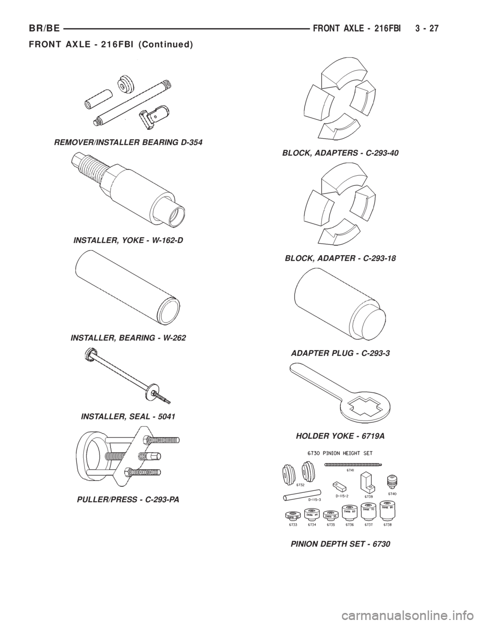
REMOVER/INSTALLER BEARING D-354
INSTALLER, YOKE - W-162-D
INSTALLER, BEARING - W-262
INSTALLER, SEAL - 5041
PULLER/PRESS - C-293-PA
BLOCK, ADAPTERS - C-293-40
BLOCK, ADAPTER - C-293-18
ADAPTER PLUG - C-293-3
HOLDER YOKE - 6719A
PINION DEPTH SET - 6730
BR/BEFRONT AXLE - 216FBI 3 - 27
FRONT AXLE - 216FBI (Continued)