Shocks DODGE RAM 2001 Service Repair Manual
[x] Cancel search | Manufacturer: DODGE, Model Year: 2001, Model line: RAM, Model: DODGE RAM 2001Pages: 2889, PDF Size: 68.07 MB
Page 54 of 2889
(5) Install the steering knuckle on the lower ball
joint. Install the lower ball joint nut and tighten to:
²LD: 129 N´m (95 ft. lbs.)
²HD: 136 N´m (110 ft. lbs.)
(5) Install the lower ball joint cotter pin.
(6) Install the stabilizer bar link on the lower sus-
pension arm. Install the grommet, retainer and nut
and tighten to 37 N´m (27 ft. lbs.).
(7) Install the tie rod end on the steering knuckle
and tighten nut to 108 N´m (80 ft. lbs.). Install cotter
pin.
(8) Install the brake rotor and caliper assembly,
(Refer to 5 - BRAKES/HYDRAULIC/MECHANICAL/
ROTORS - INSTALLATION).
(9) Install the tire and wheel assembly, (Refer to
22 - TIRES/WHEELS/WHEELS - STANDARD PRO-
CEDURE).
(10) Remove the support and lower the vehicle.
(11) Tighten the suspension arm crossmember
nuts to 169 N´m (125 ft. lbs.).
SHOCK
DESCRIPTION
The top of the shocks mounts on frame brackets
using grommets. The bottom of the shock is bolted to
the lower suspension arms.
OPERATION
The shock absorbers dampen jounce and rebound
of the vehicle over various road conditions.
DIAGNOSIS AND TESTING - SHOCK
A knocking or rattling noise from a shock absorber
may be caused by movement between mounting
bushings and metal brackets or attaching compo-
nents. These noises can usually be stopped by tight-
ening the attaching nuts. If the noise persists,
inspect for damaged and worn bushings, and attach-
ing components. Repair as necessary if any of these
conditions exist.
A squeaking noise from the shock absorber may be
caused by the hydraulic valving and may be intermit-
tent. This condition is not repairable and the shock
absorber must be replaced.
The shock absorbers are not refillable or adjust-
able. If a malfunction occurs, the shock absorber
must be replaced. To test a shock absorber, hold it in
an upright position and force the piston in and out of
the cylinder four or five times. The action throughout
each stroke should be smooth and even.
The shock absorber bushings do not require any
type of lubrication. Do not attempt to stop bushing
noise by lubricating them. Grease and mineral oil-
base lubricants will deteriorate the bushing.
REMOVAL
(1) Raise and support vehicle.
(2) Remove shock upper nut and remove retainer
and grommet.
(3) Remove lower mounting bolt from suspension
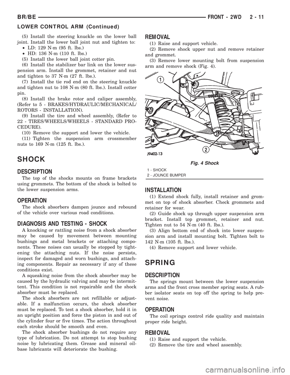
arm and remove shock (Fig. 4).
INSTALLATION
(1) Extend shock fully, install retainer and grom-
met on top of shock absorber. Check grommets and
retainer for wear.
(2) Guide shock up through upper suspension arm
bracket. Install top grommet, retainer and nut.
Tighten nut to 54 N´m (40 ft. lbs.).
(3) Align bottom end of shock into lower suspen-
sion arm and install mounting bolt. Tighten bolt to
142 N´m (105 ft. lbs.).
(4) Remove support and lower vehicle.
SPRING
DESCRIPTION
The springs mount between the lower suspension
arms and the front cross member spring seats. A rub-
ber isolator seats on top off the spring to help pre-
vent noise.
OPERATION
The coil springs control ride quality and maintain
proper ride height.
REMOVAL
(1) Raise and support the vehicle.
(2) Remove the tire and wheel assembly.
Fig. 4 Shock
1 - SHOCK
2 - JOUNCE BUMPER
BR/BEFRONT - 2WD 2 - 11
LOWER CONTROL ARM (Continued)
Page 64 of 2889
SHOCK
DESCRIPTION
The shocks are mounted inside the springs and
attached at the top to brackets with grommets. These
brackets are bolted on the frame with three studs on
a ring. The shock is mounted at the bottom of the
axle below the spring seat.
OPERATION
The shock absorbers dampen the jounce and
rebound of the vehicle over various road conditions.
DIAGNOSIS AND TESTING - SHOCK
A knocking or rattling noise from a shock absorber
may be caused by movement between mounting
bushings and metal brackets or attaching compo-
nents. These noises can usually be stopped by tight-
ening the attaching nuts. If the noise persists,
inspect for damaged and worn bushings, and attach-
ing components. Repair as necessary if any of these
conditions exist.
A squeaking noise from the shock absorber may be
caused by the hydraulic valving and may be intermit-
tent. This condition is not repairable and the shock
absorber must be replaced.
The shock absorbers are not refillable or adjust-
able. If a malfunction occurs, the shock absorbermust be replaced. To test a shock absorber, hold it in
an upright position and force the piston in and out of
the cylinder four or five times. The action throughout
each stroke should be smooth and even.
The shock absorber bushings do not require any
type of lubrication. Do not attempt to stop bushing
noise by lubricating them. Grease and mineral oil-
base lubricants will deteriorate the bushing.
REMOVAL
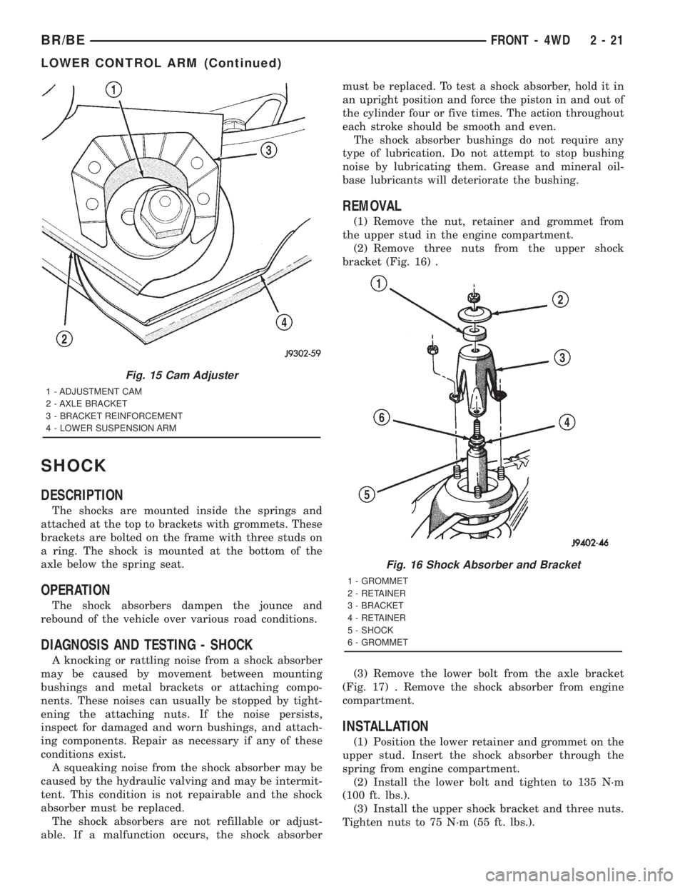
(1) Remove the nut, retainer and grommet from
the upper stud in the engine compartment.
(2) Remove three nuts from the upper shock
bracket (Fig. 16) .
(3) Remove the lower bolt from the axle bracket
(Fig. 17) . Remove the shock absorber from engine
compartment.
INSTALLATION
(1) Position the lower retainer and grommet on the
upper stud. Insert the shock absorber through the
spring from engine compartment.
(2) Install the lower bolt and tighten to 135 N´m
(100 ft. lbs.).
(3) Install the upper shock bracket and three nuts.
Tighten nuts to 75 N´m (55 ft. lbs.).
Fig. 15 Cam Adjuster
1 - ADJUSTMENT CAM
2 - AXLE BRACKET
3 - BRACKET REINFORCEMENT
4 - LOWER SUSPENSION ARM
Fig. 16 Shock Absorber and Bracket
1 - GROMMET
2 - RETAINER
3 - BRACKET
4 - RETAINER
5 - SHOCK
6 - GROMMET
BR/BEFRONT - 4WD 2 - 21
LOWER CONTROL ARM (Continued)
Page 71 of 2889
SPECIAL TOOLS
SUSPENSION-REAR
BUSHINGS
REMOVAL
(1) Remove the spring from the vehicle.
(2) Position the spring eye in a press.
(3) Press the bushing out with an appropriate size
driver.
INSTALLATION
(1) Press new bushing into the spring eye with an
appropriate size driver. The bushing should be cen-
tered in the spring eye.
(2) Install the spring on the vehicle.
JOUNCE BUMPER
DESCRIPTION
The jounce bumpers are bolted to the frame rail
above the axle.
OPERATION
The jounce bumpers are used to limit the spring
and axle travel.
SHOCK
DESCRIPTION
The top of the shock absorbers are bolted to the
body crossmember. The bottom of the shocks are
bolted to the axle bracket.
OPERATION
The shocks dampen the jounce and rebound as the
vehicle travels over various road conditions.
REMOVAL
(1) Raise vehicle and support axle.
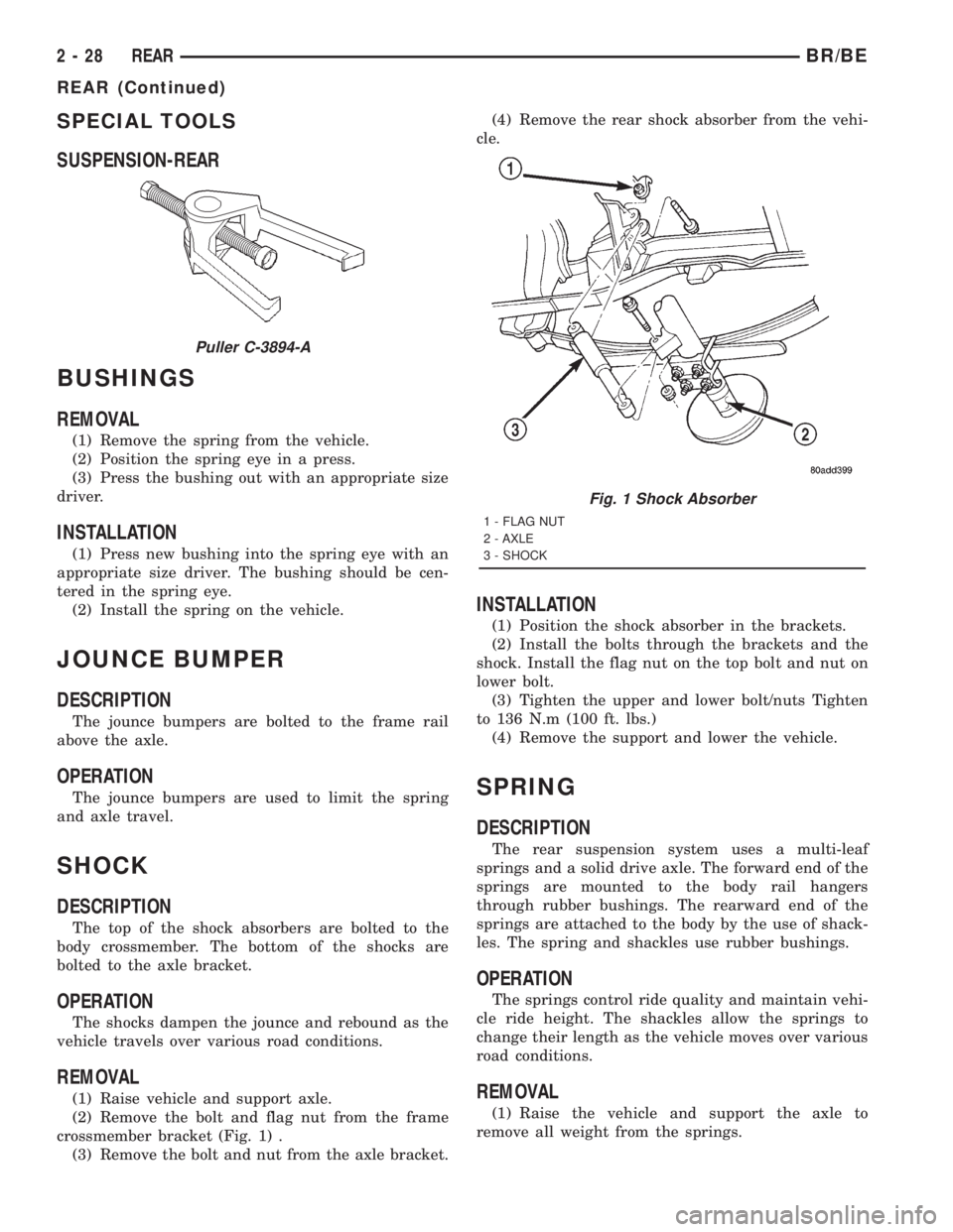
(2) Remove the bolt and flag nut from the frame
crossmember bracket (Fig. 1) .
(3) Remove the bolt and nut from the axle bracket.(4) Remove the rear shock absorber from the vehi-
cle.
INSTALLATION
(1) Position the shock absorber in the brackets.
(2) Install the bolts through the brackets and the
shock. Install the flag nut on the top bolt and nut on
lower bolt.
(3) Tighten the upper and lower bolt/nuts Tighten
to 136 N.m (100 ft. lbs.)
(4) Remove the support and lower the vehicle.
SPRING
DESCRIPTION
The rear suspension system uses a multi-leaf
springs and a solid drive axle. The forward end of the
springs are mounted to the body rail hangers
through rubber bushings. The rearward end of the
springs are attached to the body by the use of shack-
les. The spring and shackles use rubber bushings.
OPERATION
The springs control ride quality and maintain vehi-
cle ride height. The shackles allow the springs to
change their length as the vehicle moves over various
road conditions.
REMOVAL
(1) Raise the vehicle and support the axle to
remove all weight from the springs.
Puller C-3894-A
Fig. 1 Shock Absorber
1 - FLAG NUT
2 - AXLE
3 - SHOCK
2 - 28 REARBR/BE
REAR (Continued)
Page 2567 of 2889
DESCRIPTION
Radial-ply tires improve handling, tread life and
ride quality, and decrease rolling resistance.
Radial-ply tires must always be used in sets of
four. Under no circumstances should they be used on
the front only. They may be mixed with temporary
spare tires when necessary. A maximum speed of 50
MPH is recommended while a temporary spare is in
use.
Radial-ply tires have the same load-carrying capac-
ity as other types of tires of the same size. They also
use the same recommended inflation pressures.
The use of oversized tires, either in the front or
rear of the vehicle, can cause vehicle drive train fail-
ure. This could also cause inaccurate wheel speed
signals when the vehicle is equipped with Anti-Lock
Brakes.
The use of tires from different manufactures on the
same vehicle is NOT recommended. The proper tire
pressure should be maintained on all four tires.
DESCRIPTION
Where speed limits allow the vehicle to be driven
at high speeds, correct tire inflation pressure is very
important. For speeds up to and including 120 km/h
(75 mph), tires must be inflated to the pressures
shown on the tire placard. For continuous speeds inexcess of 120 km/h (75 mph), tires must be inflated
to the maximum pressure specified on the tire side-
wall.
Vehicles loaded to the maximum capacity should
not be driven at continuous speeds above 75 mph
(120 km/h).
For emergency vehicles that are driven at speeds
over 90 mph (144 km/h), special high speed tires
must be used. Consult tire manufacturer for correct
inflation pressure recommendations.
DESCRIPTION
The original equipment tires provide a proper bal-
ance of many characteristics such as:
²Ride
²Noise
²Handling
²Durability
²Tread life
²Traction
²Rolling resistance
²Speed capability
It is recommended that tires equivalent to the orig-
inal equipment tires be used when replacement is
needed.
Failure to use equivalent replacement tires may
adversely affect the safety and handling of the vehi-
cle.
The use of oversize tires may cause interference
with vehicle components. Under extremes of suspen-
sion and steering travel, interference with vehicle
components may cause tire damage.
WARNING: FAILURE TO EQUIP THE VEHICLE WITH
TIRES HAVING ADEQUATE SPEED CAPABILITY
CAN RESULT IN SUDDEN TIRE FAILURE.
DESCRIPTION
Under inflation will cause rapid shoulder wear, tire
flexing, and possible tire failure (Fig. 12) .
Over inflation will cause rapid center wear and
loss of the tire's ability to cushion shocks (Fig. 13) .
Improper inflation can cause:
²Uneven wear patterns
²Reduced tread life
²Reduced fuel economy
²Unsatisfactory ride
²Vehicle drift
For proper tire pressure specification refer to the
Tire Inflation Pressure Chart provided with the vehi-
cles Owners Manual. A Certification Label on the
drivers side door pillar provides the minimum tire
and rim size for the vehicle. The label also list the
cold inflation pressure for these tires at full load
operation
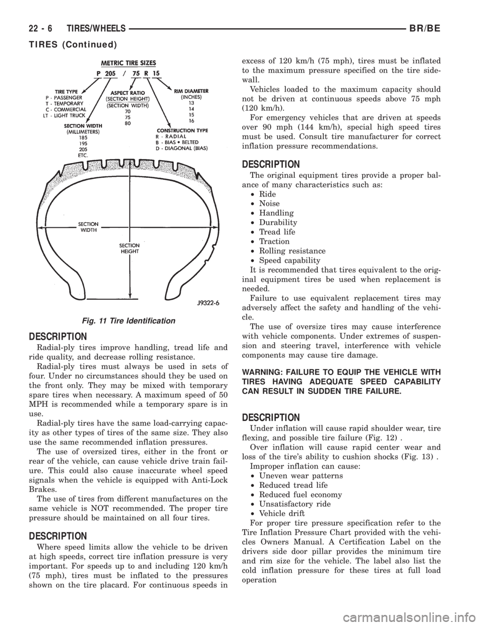
Fig. 11 Tire Identification
22 - 6 TIRES/WHEELSBR/BE
TIRES (Continued)