air conditioning DODGE RAM 2001 Service Repair Manual
[x] Cancel search | Manufacturer: DODGE, Model Year: 2001, Model line: RAM, Model: DODGE RAM 2001Pages: 2889, PDF Size: 68.07 MB
Page 1 of 2889
GROUP TAB LOCATOR
Introduction
0Lubrication & Maintenance
2Suspension
3Differential & Driveline
5Brakes
7Cooling
8AAudio
8BChime/Buzzer
8EElectronic Control Modules
8FEngine Systems
8GHeated Systems
8HHorn
8IIgnition Control
8JInstrument Cluster
8LLamps
8MMessage Systems
8NPower Systems
8ORestraints
8PSpeed Control
8QVehicle Theft Security
8RWipers/Washers
8WWiring
9Engine
11Exhaust System
13Frame & Bumpers
14Fuel System
19Steering
21Transmission/Transaxle
22Tires/Wheels
23Body
24Heating & Air Conditioning
25Emissions Control Systems
30New Vehicle Preparation
Component and System Index
Service Manual Comment Forms (Rear of Manual)
Page 339 of 2889
OPERATIONÐCOOLING SYSTEM
The cooling system regulates engine operating tem-
perature. It allows the engine to reach normal oper-
ating temperature as quickly as possible. It also
maintains normal operating temperature and pre-
vents overheating.
The cooling system also provides a means of heat-
ing the passenger compartment and cooling the auto-
matic transmission fluid (if equipped). The cooling
system is pressurized and uses a centrifugal water
pump to circulate coolant throughout the system.
An optional factory installed maximum duty cool-
ing package is available on most models. This pack-
age will provide additional cooling capacity for
vehicles used under extreme conditions such as
trailer towing in high ambient temperatures.
DIAGNOSIS AND TESTING - PRELIMINARY
CHECKS
ENGINE COOLING SYSTEM OVERHEATING
Establish what driving conditions caused the com-
plaint. Abnormal loads on the cooling system such as
the following may be the cause:
²PROLONGED IDLE
²VERY HIGH AMBIENT TEMPERATURE
²SLIGHT TAIL WIND AT IDLE
²SLOW TRAFFIC
²TRAFFIC JAMS
²HIGH SPEED OR STEEP GRADES
Driving techniques that avoid overheating are:
²Idle with A/C off when temperature gauge is at
end of normal range.²Increasing engine speed for more air flow is rec-
ommended.
TRAILER TOWING:
Consult Trailer Towing section of owners manual.
Do not exceed limits.
AIR CONDITIONING; ADD-ON OR AFTER MARKET:
A maximum cooling package should have been
ordered with vehicle if add-on or after market A/C is
installed. If not, maximum cooling system compo-
nents should be installed for model involved per
manufacturer's specifications.
RECENT SERVICE OR ACCIDENT REPAIR:
Determine if any recent service has been per-
formed on vehicle that may effect cooling system.
This may be:
²Engine adjustments (incorrect timing)
²Slipping engine accessory drive belt(s)
²Brakes (possibly dragging)
²Changed parts. Incorrect water pump or pump
rotating in wrong direction due to belt not correctly
routed
²Reconditioned radiator or cooling system refill-
ing (possibly under filled or air trapped in system).
NOTE: If investigation reveals none of the previous
items as a cause for an engine overheating com-
plaint, (Refer to 7 - COOLING - DIAGNOSIS AND
TESTING)
DIAGNOSIS AND TESTINGÐON-BOARD
DIAGNOSTICS (OBD)
COOLING SYSTEM RELATED DIAGNOSTICS
The powertrain control module (PCM) has been
programmed to monitor certain cooling system com-
ponents:
²If the engine has remained cool for too long a
period, such as with a stuck open thermostat, a Diag-
nostic Trouble Code (DTC) can be set.
²If an open or shorted condition has developed in
the relay circuit controlling the electric radiator fan,
a Diagnostic Trouble Code (DTC) can be set.
If the problem is sensed in a monitored circuit
often enough to indicated an actual problem, a DTC
is stored. The DTC will be stored in the PCM mem-
ory for eventual display to the service technician.
(Refer to 25 - EMISSIONS CONTROL - DESCRIP-
TION).
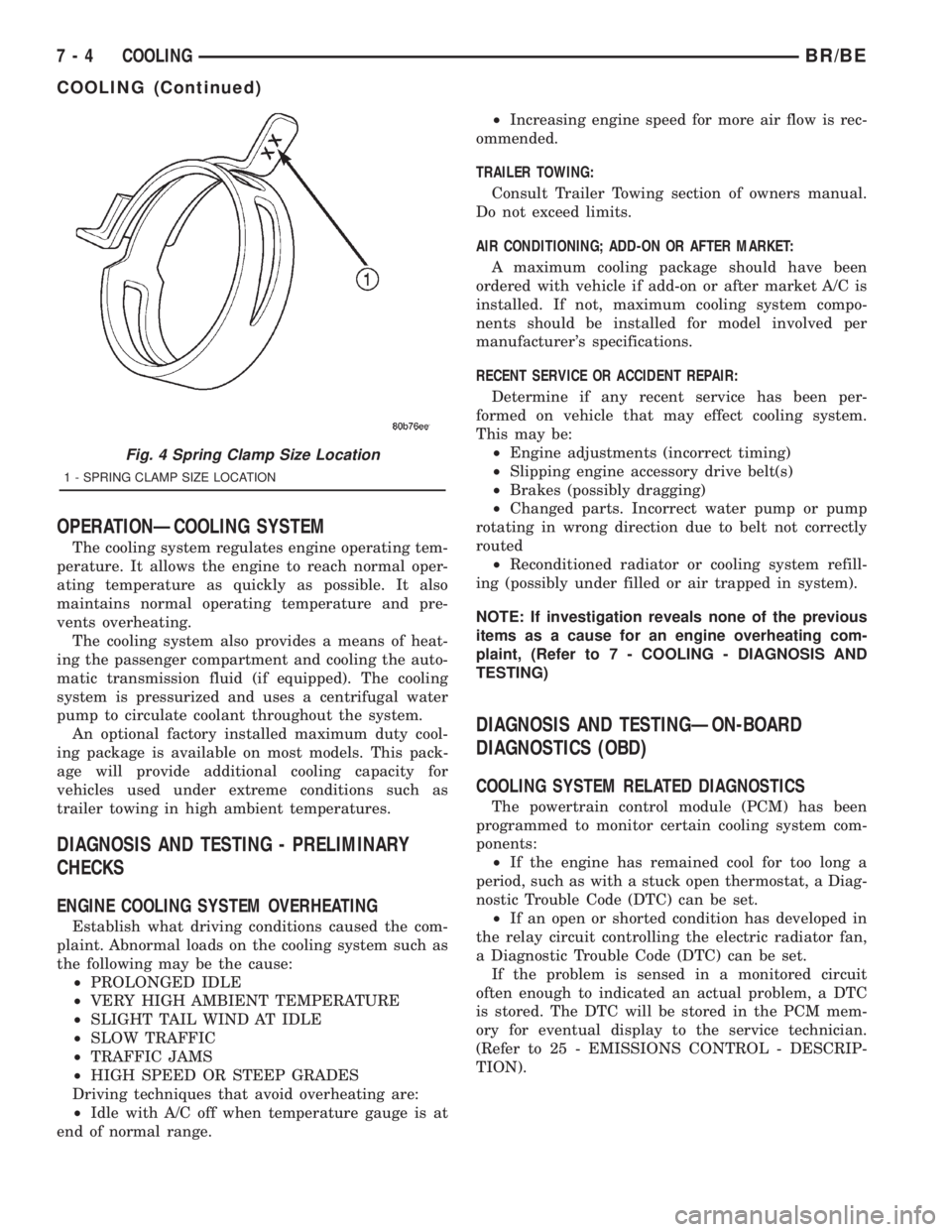
Fig. 4 Spring Clamp Size Location
1 - SPRING CLAMP SIZE LOCATION
7 - 4 COOLINGBR/BE
COOLING (Continued)
Page 342 of 2889
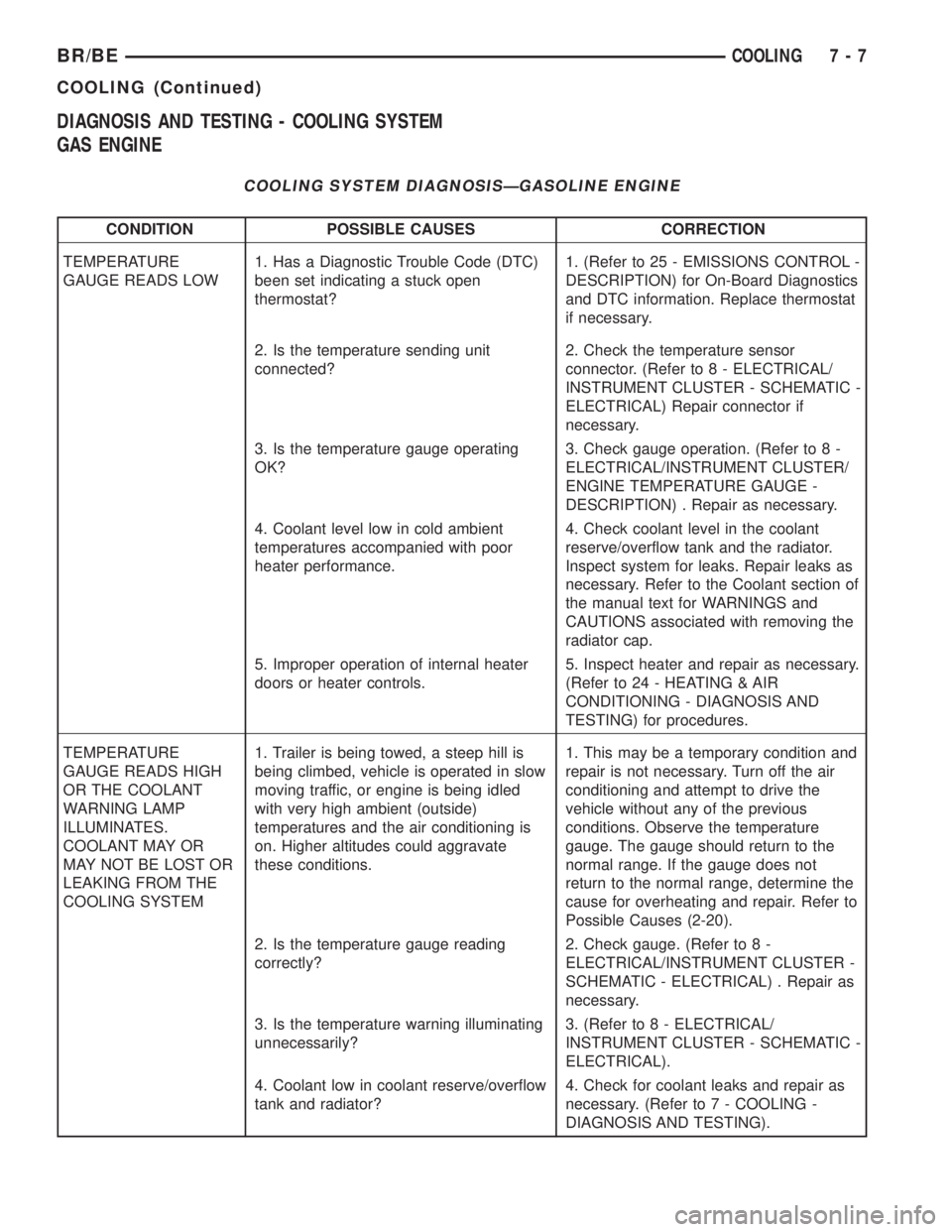
DIAGNOSIS AND TESTING - COOLING SYSTEM
GAS ENGINE
COOLING SYSTEM DIAGNOSISÐGASOLINE ENGINE
CONDITION POSSIBLE CAUSES CORRECTION
TEMPERATURE
GAUGE READS LOW1. Has a Diagnostic Trouble Code (DTC)
been set indicating a stuck open
thermostat?1. (Refer to 25 - EMISSIONS CONTROL -
DESCRIPTION) for On-Board Diagnostics
and DTC information. Replace thermostat
if necessary.
2. Is the temperature sending unit
connected?2. Check the temperature sensor
connector. (Refer to 8 - ELECTRICAL/
INSTRUMENT CLUSTER - SCHEMATIC -
ELECTRICAL) Repair connector if
necessary.
3. Is the temperature gauge operating
OK?3. Check gauge operation. (Refer to 8 -
ELECTRICAL/INSTRUMENT CLUSTER/
ENGINE TEMPERATURE GAUGE -
DESCRIPTION) . Repair as necessary.
4. Coolant level low in cold ambient
temperatures accompanied with poor
heater performance.4. Check coolant level in the coolant
reserve/overflow tank and the radiator.
Inspect system for leaks. Repair leaks as
necessary. Refer to the Coolant section of
the manual text for WARNINGS and
CAUTIONS associated with removing the
radiator cap.
5. Improper operation of internal heater
doors or heater controls.5. Inspect heater and repair as necessary.
(Refer to 24 - HEATING & AIR
CONDITIONING - DIAGNOSIS AND
TESTING) for procedures.
TEMPERATURE
GAUGE READS HIGH
OR THE COOLANT
WARNING LAMP
ILLUMINATES.
COOLANT MAY OR
MAY NOT BE LOST OR
LEAKING FROM THE
COOLING SYSTEM1. Trailer is being towed, a steep hill is
being climbed, vehicle is operated in slow
moving traffic, or engine is being idled
with very high ambient (outside)
temperatures and the air conditioning is
on. Higher altitudes could aggravate
these conditions.1. This may be a temporary condition and
repair is not necessary. Turn off the air
conditioning and attempt to drive the
vehicle without any of the previous
conditions. Observe the temperature
gauge. The gauge should return to the
normal range. If the gauge does not
return to the normal range, determine the
cause for overheating and repair. Refer to
Possible Causes (2-20).
2. Is the temperature gauge reading
correctly?2. Check gauge. (Refer to 8 -
ELECTRICAL/INSTRUMENT CLUSTER -
SCHEMATIC - ELECTRICAL) . Repair as
necessary.
3. Is the temperature warning illuminating
unnecessarily?3. (Refer to 8 - ELECTRICAL/
INSTRUMENT CLUSTER - SCHEMATIC -
ELECTRICAL).
4. Coolant low in coolant reserve/overflow
tank and radiator?4. Check for coolant leaks and repair as
necessary. (Refer to 7 - COOLING -
DIAGNOSIS AND TESTING).
BR/BECOOLING 7 - 7
COOLING (Continued)
Page 344 of 2889
CONDITION POSSIBLE CAUSES CORRECTION
16. Thermostat partially or completely
shut.16. Check thermostat operation and
replace as necessary. (Refer to 7 -
COOLING/ENGINE/ENGINE COOLANT
THERMOSTAT - REMOVAL) .
17. Viscous fan drive not operating
properly.17. Check fan drive operation and replace
as necessary. (Refer to 7 - COOLING/
ENGINE/FAN DRIVE VISCOUS CLUTCH
- REMOVAL) .
18. Cylinder head gasket leaking. 18. Check for cylinder head gasket leaks.
(Refer to 7 - COOLING - DIAGNOSIS
AND TESTING).
19. Heater core leaking. 19. Check heater core for leaks. (Refer to
24 - HEATING & AIR CONDITIONING/
PLUMBING - DIAGNOSIS AND
TESTING). Repair as necessary.
TEMPERATURE
GAUGE READING IS
INCONSISTENT
(FLUCTUATES,
CYCLES OR IS
ERRATIC)1. During cold weather operation, with the
heater blower in the high position, the
gauge reading may drop slightly.1. A normal condition. No correction is
necessary.
2. Temperature gauge or engine mounted
gauge sensor defective or shorted. Also,
corroded or loose wiring in this circuit.2. Check operation of gauge and repair if
necessary. (Refer to 8 - ELECTRICAL/
INSTRUMENT CLUSTER - DIAGNOSIS
AND TESTING).
3. Gauge reading rises when vehicle is
brought to a stop after heavy use (engine
still running)3. A normal condition. No correction is
necessary. Gauge should return to normal
range after vehicle is driven.
4. Gauge reading high after re-starting a
warmed up (hot) engine.4. A normal condition. No correction is
necessary. The gauge should return to
normal range after a few minutes of
engine operation.
5. Coolant level low in radiator (air will
build up in the cooling system causing
the thermostat to open late).5. Check and correct coolant leaks. (Refer
to 7 - COOLING - DIAGNOSIS AND
TESTING).
6. Cylinder head gasket leaking allowing
exhaust gas to enter cooling system
causing a thermostat to open late.6. (a) Check for cylinder head gasket
leaks. (Refer to 7 - COOLING -
DIAGNOSIS AND TESTING).
(b) Check for coolant in the engine oil.
Inspect for white steam emitting from the
exhaust system. Repair as necessary.
7. Water pump impeller loose on shaft. 7. Check water pump and replace as
necessary. (Refer to 7 - COOLING/
ENGINE/WATER PUMP - REMOVAL).
8. Loose accessory drive belt. (water
pump slipping)8. (Refer to 7 - COOLING/ACCESSORY
DRIVE/DRIVE BELTS - DIAGNOSIS AND
TESTING). Check and correct as
necessary.
9. Air leak on the suction side of the
water pump allows air to build up in
cooling system causing thermostat to
open late.9. Locate leak and repair as necessary.
BR/BECOOLING 7 - 9
COOLING (Continued)
Page 346 of 2889
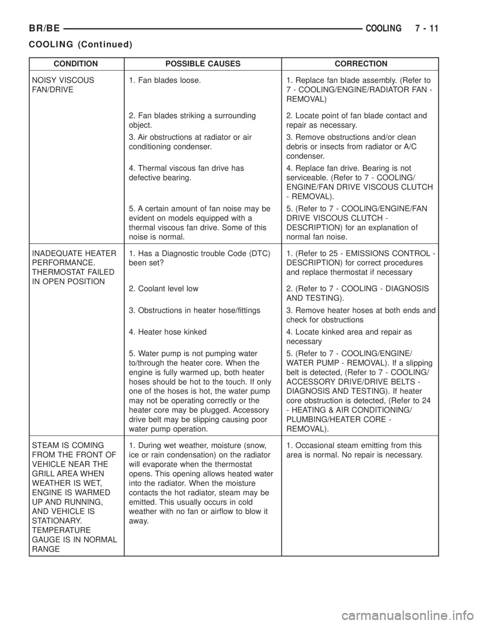
CONDITION POSSIBLE CAUSES CORRECTION
NOISY VISCOUS
FAN/DRIVE1. Fan blades loose. 1. Replace fan blade assembly. (Refer to
7 - COOLING/ENGINE/RADIATOR FAN -
REMOVAL)
2. Fan blades striking a surrounding
object.2. Locate point of fan blade contact and
repair as necessary.
3. Air obstructions at radiator or air
conditioning condenser.3. Remove obstructions and/or clean
debris or insects from radiator or A/C
condenser.
4. Thermal viscous fan drive has
defective bearing.4. Replace fan drive. Bearing is not
serviceable. (Refer to 7 - COOLING/
ENGINE/FAN DRIVE VISCOUS CLUTCH
- REMOVAL).
5. A certain amount of fan noise may be
evident on models equipped with a
thermal viscous fan drive. Some of this
noise is normal.5. (Refer to 7 - COOLING/ENGINE/FAN
DRIVE VISCOUS CLUTCH -
DESCRIPTION) for an explanation of
normal fan noise.
INADEQUATE HEATER
PERFORMANCE.
THERMOSTAT FAILED
IN OPEN POSITION1. Has a Diagnostic trouble Code (DTC)
been set?1. (Refer to 25 - EMISSIONS CONTROL -
DESCRIPTION) for correct procedures
and replace thermostat if necessary
2. Coolant level low 2. (Refer to 7 - COOLING - DIAGNOSIS
AND TESTING).
3. Obstructions in heater hose/fittings 3. Remove heater hoses at both ends and
check for obstructions
4. Heater hose kinked 4. Locate kinked area and repair as
necessary
5. Water pump is not pumping water
to/through the heater core. When the
engine is fully warmed up, both heater
hoses should be hot to the touch. If only
one of the hoses is hot, the water pump
may not be operating correctly or the
heater core may be plugged. Accessory
drive belt may be slipping causing poor
water pump operation.5. (Refer to 7 - COOLING/ENGINE/
WATER PUMP - REMOVAL). If a slipping
belt is detected, (Refer to 7 - COOLING/
ACCESSORY DRIVE/DRIVE BELTS -
DIAGNOSIS AND TESTING). If heater
core obstruction is detected, (Refer to 24
- HEATING & AIR CONDITIONING/
PLUMBING/HEATER CORE -
REMOVAL).
STEAM IS COMING
FROM THE FRONT OF
VEHICLE NEAR THE
GRILL AREA WHEN
WEATHER IS WET,
ENGINE IS WARMED
UP AND RUNNING,
AND VEHICLE IS
STATIONARY.
TEMPERATURE
GAUGE IS IN NORMAL
RANGE1. During wet weather, moisture (snow,
ice or rain condensation) on the radiator
will evaporate when the thermostat
opens. This opening allows heated water
into the radiator. When the moisture
contacts the hot radiator, steam may be
emitted. This usually occurs in cold
weather with no fan or airflow to blow it
away.1. Occasional steam emitting from this
area is normal. No repair is necessary.
BR/BECOOLING 7 - 11
COOLING (Continued)
Page 354 of 2889
ACCESSORY DRIVE
TABLE OF CONTENTS
page page
BELT TENSIONERS - 3.9L/5.2L/5.9L
DESCRIPTION...........................19
OPERATION.............................19
REMOVAL..............................20
INSTALLATION...........................20
BELT TENSIONERS - 8.0L
DESCRIPTION...........................20
OPERATION.............................20
REMOVAL..............................21
INSTALLATION...........................22
BELT TENSIONERS - 5.9L DIESEL
DESCRIPTION...........................23
OPERATION.............................23
REMOVAL..............................23
INSTALLATION...........................23
DRIVE BELTS - 3.9L/5.2L/5.9L
DIAGNOSIS AND TESTING.................24
ACCESSORY DRIVE BELT................24
REMOVAL..............................26INSTALLATION...........................27
DRIVE BELTS - 8.0L
DIAGNOSIS AND TESTING.................27
ACCESSORY DRIVE BELT................27
REMOVAL..............................30
INSTALLATION...........................30
DRIVE BELTS - 5.9L DIESEL
DIAGNOSIS AND TESTING.................31
ACCESSORY DRIVE BELT................31
REMOVAL..............................33
INSTALLATION...........................34
VACUUM PUMP - 5.9L DIESEL
DESCRIPTION...........................34
OPERATION.............................35
DIAGNOSIS AND TESTING.................35
VACUUM PUMP OUTPUT.................35
REMOVAL..............................35
INSTALLATION...........................37
BELT TENSIONERS - 3.9L/5.2L/
5.9L
DESCRIPTION
Correct drive belt tension is required to ensure
optimum performance of the belt driven engine acces-
sories. If specified tension is not maintained, belt
slippage may cause; engine overheating, lack of
power steering assist, loss of air conditioning capac-
ity, reduced generator output rate, and greatly
reduced belt life.
It is not necessary to adjust belt tension on the
3.9L/5.2L or 5.9L engines. These engines are
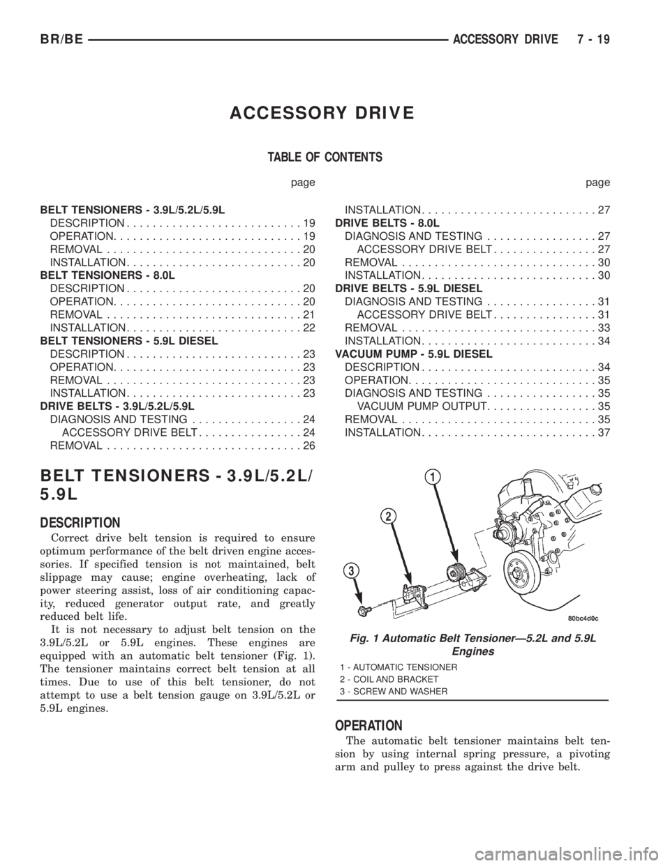
equipped with an automatic belt tensioner (Fig. 1).
The tensioner maintains correct belt tension at all
times. Due to use of this belt tensioner, do not
attempt to use a belt tension gauge on 3.9L/5.2L or
5.9L engines.
OPERATION
The automatic belt tensioner maintains belt ten-
sion by using internal spring pressure, a pivoting
arm and pulley to press against the drive belt.
Fig. 1 Automatic Belt TensionerÐ5.2L and 5.9L
Engines
1 - AUTOMATIC TENSIONER
2 - COIL AND BRACKET
3 - SCREW AND WASHER
BR/BEACCESSORY DRIVE 7 - 19
Page 355 of 2889
REMOVAL
WARNING: BECAUSE OF HIGH SPRING PRES-
SURE, DO NOT ATTEMPT TO DISASSEMBLE AUTO-
MATIC TENSIONER. UNIT IS SERVICED AS AN
ASSEMBLY (EXCEPT FOR PULLEY).
(1) Remove accessory drive belt. (Refer to 7 -
COOLING/ACCESSORY DRIVE/DRIVE BELTS -
REMOVAL).
(2) Disconnect wiring and secondary cable from
ignition coil.
(3) Remove ignition coil from coil mounting
bracket (two bolts). Do not remove coil mounting
bracket from cylinder head.
(4) Remove tensioner assembly from mounting
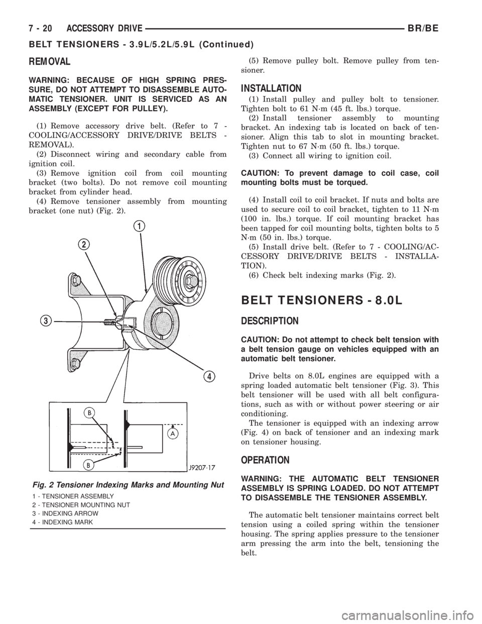
bracket (one nut) (Fig. 2).(5) Remove pulley bolt. Remove pulley from ten-
sioner.
INSTALLATION
(1) Install pulley and pulley bolt to tensioner.
Tighten bolt to 61 N´m (45 ft. lbs.) torque.
(2) Install tensioner assembly to mounting
bracket. An indexing tab is located on back of ten-
sioner. Align this tab to slot in mounting bracket.
Tighten nut to 67 N´m (50 ft. lbs.) torque.
(3) Connect all wiring to ignition coil.
CAUTION: To prevent damage to coil case, coil
mounting bolts must be torqued.
(4) Install coil to coil bracket. If nuts and bolts are
used to secure coil to coil bracket, tighten to 11 N´m
(100 in. lbs.) torque. If coil mounting bracket has
been tapped for coil mounting bolts, tighten bolts to 5
N´m (50 in. lbs.) torque.
(5) Install drive belt. (Refer to 7 - COOLING/AC-
CESSORY DRIVE/DRIVE BELTS - INSTALLA-
TION).
(6) Check belt indexing marks (Fig. 2).
BELT TENSIONERS - 8.0L
DESCRIPTION
CAUTION: Do not attempt to check belt tension with
a belt tension gauge on vehicles equipped with an
automatic belt tensioner.
Drive belts on 8.0L engines are equipped with a
spring loaded automatic belt tensioner (Fig. 3). This
belt tensioner will be used with all belt configura-
tions, such as with or without power steering or air
conditioning.
The tensioner is equipped with an indexing arrow
(Fig. 4) on back of tensioner and an indexing mark
on tensioner housing.
OPERATION
WARNING: THE AUTOMATIC BELT TENSIONER
ASSEMBLY IS SPRING LOADED. DO NOT ATTEMPT
TO DISASSEMBLE THE TENSIONER ASSEMBLY.
The automatic belt tensioner maintains correct belt
tension using a coiled spring within the tensioner
housing. The spring applies pressure to the tensioner
arm pressing the arm into the belt, tensioning the
belt.Fig. 2 Tensioner Indexing Marks and Mounting Nut
1 - TENSIONER ASSEMBLY
2 - TENSIONER MOUNTING NUT
3 - INDEXING ARROW
4 - INDEXING MARK
7 - 20 ACCESSORY DRIVEBR/BE
BELT TENSIONERS - 3.9L/5.2L/5.9L (Continued)
Page 365 of 2889
REMOVAL
Drive belts are equipped with a spring loaded auto-
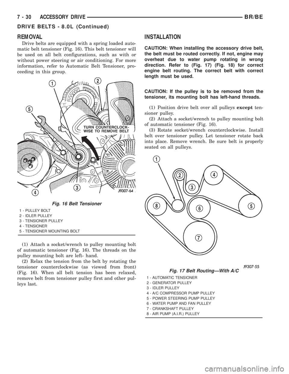
matic belt tensioner (Fig. 16). This belt tensioner will
be used on all belt configurations, such as with or
without power steering or air conditioning. For more
information, refer to Automatic Belt Tensioner, pro-
ceeding in this group.
(1) Attach a socket/wrench to pulley mounting bolt
of automatic tensioner (Fig. 16). The threads on the
pulley mounting bolt are left- hand.
(2) Relax the tension from the belt by rotating the
tensioner counterclockwise (as viewed from front)
(Fig. 16). When all belt tension has been relaxed,
remove belt from tensioner pulley first and other pul-
leys last.
INSTALLATION
CAUTION: When installing the accessory drive belt,
the belt must be routed correctly. If not, engine may
overheat due to water pump rotating in wrong
direction. Refer to (Fig. 17) (Fig. 18) for correct
engine belt routing. The correct belt with correct
length must be used.
CAUTION: If the pulley is to be removed from the
tensioner, its mounting bolt has left-hand threads.
(1) Position drive belt over all pulleysexceptten-
sioner pulley.
(2) Attach a socket/wrench to pulley mounting bolt
of automatic tensioner (Fig. 16).
(3) Rotate socket/wrench counterclockwise. Install
belt over tensioner pulley. Let tensioner rotate back
into place. Remove wrench. Be sure belt is properly
seated on all pulleys.
Fig. 16 Belt Tensioner
1 - PULLEY BOLT
2 - IDLER PULLEY
3 - TENSIONER PULLEY
4 - TENSIONER
5 - TENSIONER MOUNTING BOLT
Fig. 17 Belt RoutingÐWith A/C
1 - AUTOMATIC TENSIONER
2 - GENERATOR PULLEY
3 - IDLER PULLEY
4 - A/C COMPRESSOR PUMP PULLEY
5 - POWER STEERING PUMP PULLEY
6 - WATER PUMP AND FAN PULLEY
7 - CRANKSHAFT PULLEY
8 - AIR PUMP (A.I.R.) PULLEY
7 - 30 ACCESSORY DRIVEBR/BE
DRIVE BELTS - 8.0L (Continued)
Page 368 of 2889
CONDITION POSSIBLE CAUSES CORRECTION
NOISE (Objectional squeal, spueak,
or rumble is heard or felt while drive
belt is in operation)1. Incorrect belt tension 1. Inspect/Replace tensioner if
necessary
2. Bearing noise 2. Locate and repair
3. Belt misalignment 3. Align belt/pulley(s)
4. Belt to pulley mismatch 4. Install correct belt
5. Driven component induced
vibration5. Locate defective driven
component and repair
TENSION SHEETING FABRIC
FAILURE
(Woven fabric on outside,
circumference of belt has cracked or
separated from body of belt)1. Tension sheeting contacting
stationary object1. Correct rubbing condition
2. Excessive heat causing woven
fabric to age2. Replace belt
3. Tension sheeting splice has
fractured3. Replace belt
CORD EDGE FAILURE
(Tensile member exposed at edges
of belt or separated from belt body)1. Incorrect belt tension 1. Inspect/Replace tensioner if
necessary
2. Belt contacting stationary object 2. Replace belt
3. Pulley(s) out of tolerance 3. Replace pulley
4. Insufficient adhesion between
tensile member and rubber matrix4. Replace belt
REMOVAL
CAUTION: Do not attempt to check belt tension with
a belt tension gauge on vehicles equipped with an
automatic belt tensioner. Refer to Automatic Belt
Tensioner in this group.
NOTE: The belt routing schematics are published
from the latest information available at the time of
publication. If anything differs between these sche-
matics and the Belt Routing Label, use the sche-
matics on Belt Routing Label.This label is located in
the engine compartment.
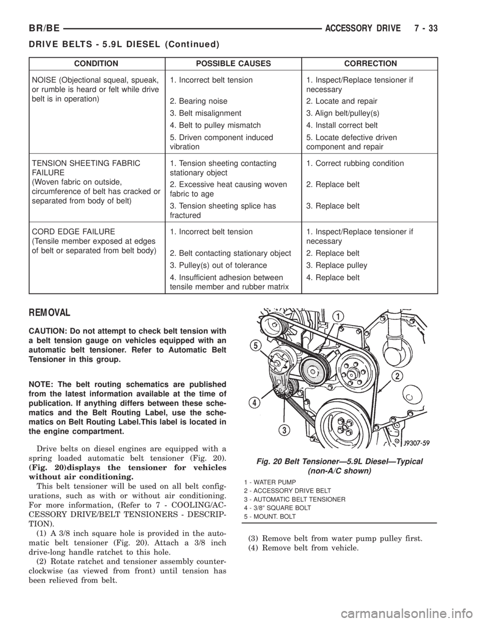
Drive belts on diesel engines are equipped with a
spring loaded automatic belt tensioner (Fig. 20).
(Fig. 20)displays the tensioner for vehicles
without air conditioning.
This belt tensioner will be used on all belt config-
urations, such as with or without air conditioning.
For more information, (Refer to 7 - COOLING/AC-
CESSORY DRIVE/BELT TENSIONERS - DESCRIP-
TION).
(1) A 3/8 inch square hole is provided in the auto-
matic belt tensioner (Fig. 20). Attach a 3/8 inch
drive-long handle ratchet to this hole.
(2) Rotate ratchet and tensioner assembly counter-
clockwise (as viewed from front) until tension has
been relieved from belt.(3) Remove belt from water pump pulley first.
(4) Remove belt from vehicle.
Fig. 20 Belt TensionerÐ5.9L DieselÐTypical
(non-A/C shown)
1 - WATER PUMP
2 - ACCESSORY DRIVE BELT
3 - AUTOMATIC BELT TENSIONER
4 - 3/89SQUARE BOLT
5 - MOUNT. BOLT
BR/BEACCESSORY DRIVE 7 - 33
DRIVE BELTS - 5.9L DIESEL (Continued)
Page 383 of 2889
ENGINE COOLANT TEMP
SENSOR - 3.9L/5.2L/5.9L
DESCRIPTION
The Engine Coolant Temperature (ECT) sensor is
used to sense engine coolant temperature. The sensor
protrudes into an engine water jacket.
The ECT sensor is a two-wire Negative Thermal
Coefficient (NTC) sensor. Meaning, as engine coolant
temperature increases, resistance (voltage) in the
sensor decreases. As temperature decreases, resis-
tance (voltage) in the sensor increases.
OPERATION
At key-on, the Powertrain Control Module (PCM)
sends out a regulated 5 volt signal to the ECT sensor.
The PCM then monitors the signal as it passes
through the ECT sensor to the sensor ground (sensor
return).
When the engine is cold, the PCM will operate in
Open Loop cycle. It will demand slightly richer air-
fuel mixtures and higher idle speeds. This is done
until normal operating temperatures are reached.
The PCM uses inputs from the ECT sensor for the
following calculations:
²for engine coolant temperature gauge operation
through CCD or PCI (J1850) communications
²Injector pulse-width
²Spark-advance curves
²ASD relay shut-down times
²Idle Air Control (IAC) motor key-on steps
²Pulse-width prime-shot during cranking
²O2 sensor closed loop times
²Purge solenoid on/off times
²EGR solenoid on/off times (if equipped)
²Leak Detection Pump operation (if equipped)²Radiator fan relay on/off times (if equipped)
²Target idle speed
REMOVAL
WARNING: HOT, PRESSURIZED COOLANT CAN
CAUSE INJURY BY SCALDING. COOLING SYSTEM
MUST BE PARTIALLY DRAINED BEFORE REMOV-
ING THE COOLANT TEMPERATURE SENSOR.
REFER TO GROUP 7, COOLING.
(1) Partially drain cooling system (Refer to 7 -
COOLING - STANDARD PROCEDURE).
(2) Remove air cleaner assembly.
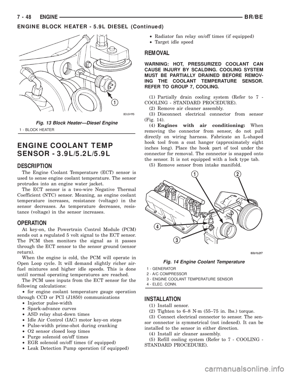
(3) Disconnect electrical connector from sensor
(Fig. 14).
(4)Engines with air conditioning:When
removing the connector from sensor, do not pull
directly on wiring harness. Fabricate an L-shaped
hook tool from a coat hanger (approximately eight
inches long). Place the hook part of tool under the
connector for removal. The connector is snapped onto
the sensor. It is not equipped with a lock type tab.
(5) Remove sensor from intake manifold.
INSTALLATION
(1) Install sensor.
(2) Tighten to 6±8 N´m (55±75 in. lbs.) torque.
(3) Connect electrical connector to sensor. The sen-
sor connector is symmetrical (not indexed). It can be
installed to the sensor in either direction.
(4) Install air cleaner assembly.
(5) Refill cooling system (Refer to 7 - COOLING -
STANDARD PROCEDURE).
Fig. 13 Block HeaterÐDiesel Engine
1 - BLOCK HEATER
Fig. 14 Engine Coolant Temperature
1 - GENERATOR
2 - A/C COMPRESSOR
3 - ENGINE COOLANT TEMPERATURE SENSOR
4 - ELEC. CONN.
7 - 48 ENGINEBR/BE
ENGINE BLOCK HEATER - 5.9L DIESEL (Continued)