antifreeze coolant DODGE RAM 2001 Service Repair Manual
[x] Cancel search | Manufacturer: DODGE, Model Year: 2001, Model line: RAM, Model: DODGE RAM 2001Pages: 2889, PDF Size: 68.07 MB
Page 350 of 2889
STANDARD PROCEDUREÐDRAINING
COOLING SYSTEM 3.9L/5.2L/5.9L/8.0L
ENGINES
WARNING: DO NOT REMOVE CYLINDER BLOCK
DRAIN PLUGS OR LOOSEN RADIATOR DRAIN-
COCK WITH SYSTEM HOT AND UNDER PRESSURE.
SERIOUS BURNS FROM COOLANT CAN OCCUR.
DO NOT WASTE reusable coolant. If solution is
clean, drain coolant into a clean container for reuse.
(1) Remove radiator pressure cap.
(2) Loosen radiator petcock.
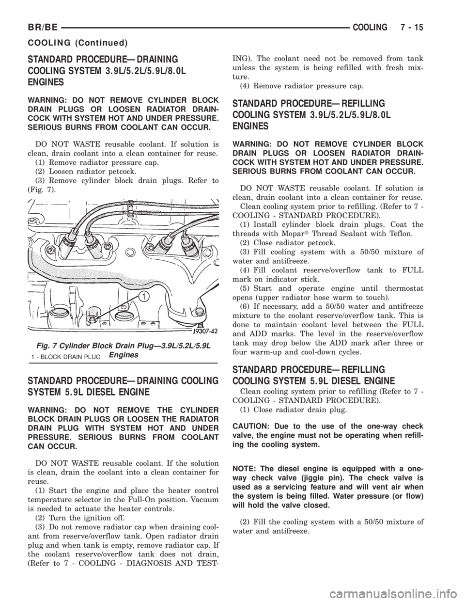
(3) Remove cylinder block drain plugs. Refer to
(Fig. 7).
STANDARD PROCEDUREÐDRAINING COOLING
SYSTEM 5.9L DIESEL ENGINE
WARNING: DO NOT REMOVE THE CYLINDER
BLOCK DRAIN PLUGS OR LOOSEN THE RADIATOR
DRAIN PLUG WITH SYSTEM HOT AND UNDER
PRESSURE. SERIOUS BURNS FROM COOLANT
CAN OCCUR.
DO NOT WASTE reusable coolant. If the solution
is clean, drain the coolant into a clean container for
reuse.
(1) Start the engine and place the heater control
temperature selector in the Full-On position. Vacuum
is needed to actuate the heater controls.
(2) Turn the ignition off.
(3) Do not remove radiator cap when draining cool-
ant from reserve/overflow tank. Open radiator drain
plug and when tank is empty, remove radiator cap. If
the coolant reserve/overflow tank does not drain,
(Refer to 7 - COOLING - DIAGNOSIS AND TEST-ING). The coolant need not be removed from tank
unless the system is being refilled with fresh mix-
ture.
(4) Remove radiator pressure cap.
STANDARD PROCEDUREÐREFILLING
COOLING SYSTEM 3.9L/5.2L/5.9L/8.0L
ENGINES
WARNING: DO NOT REMOVE CYLINDER BLOCK
DRAIN PLUGS OR LOOSEN RADIATOR DRAIN-
COCK WITH SYSTEM HOT AND UNDER PRESSURE.
SERIOUS BURNS FROM COOLANT CAN OCCUR.
DO NOT WASTE reusable coolant. If solution is
clean, drain coolant into a clean container for reuse.
Clean cooling system prior to refilling. (Refer to 7 -
COOLING - STANDARD PROCEDURE).
(1) Install cylinder block drain plugs. Coat the
threads with MopartThread Sealant with Teflon.
(2) Close radiator petcock.
(3) Fill cooling system with a 50/50 mixture of
water and antifreeze.
(4) Fill coolant reserve/overflow tank to FULL
mark on indicator stick.
(5) Start and operate engine until thermostat
opens (upper radiator hose warm to touch).
(6) If necessary, add a 50/50 water and antifreeze
mixture to the coolant reserve/overflow tank. This is
done to maintain coolant level between the FULL
and ADD marks. The level in the reserve/overflow
tank may drop below the ADD mark after three or
four warm-up and cool-down cycles.
STANDARD PROCEDUREÐREFILLING
COOLING SYSTEM 5.9L DIESEL ENGINE
Clean cooling system prior to refilling (Refer to 7 -
COOLING - STANDARD PROCEDURE).
(1) Close radiator drain plug.
CAUTION: Due to the use of the one-way check
valve, the engine must not be operating when refill-
ing the cooling system.
NOTE: The diesel engine is equipped with a one-
way check valve (jiggle pin). The check valve is
used as a servicing feature and will vent air when
the system is being filled. Water pressure (or flow)
will hold the valve closed.
(2) Fill the cooling system with a 50/50 mixture of
water and antifreeze.
Fig. 7 Cylinder Block Drain PlugÐ3.9L/5.2L/5.9L
Engines
1 - BLOCK DRAIN PLUG
BR/BECOOLING 7 - 15
COOLING (Continued)
Page 351 of 2889
(3) Fill coolant reserve/overflow tank to the FULL
mark.
(4) Start and operate engine until thermostat
opens. Upper radiator hose should be warm to touch.
(5) If necessary, add 50/50 water and antifreeze
mixture to the coolant reserve/overflow tank to main-
tain coolant level. This level should be between the
ADD and FULL marks. The level in the reserve/over-
flow tank may drop below the ADD mark after three
or four warm-up and cool-down cycles.
STANDARD PROCEDUREÐADDING
ADDITIONAL COOLANT
Do not remove radiator cap to add coolant to
system.When adding coolant to maintain correct
level, do so at coolant reserve/overflow tank. Use a
50/50 mixture of ethylene glycol antifreeze containing
Alugard 340-2yand low mineral content water.
Remove radiator cap only for testing or when refill-
ing system after service. Removing cap unnecessarily
can cause loss of coolant and allow air to enter sys-
tem, which produces corrosion.
STANDARD PROCEDUREÐCOOLANT LEVEL
CHECK
NOTE: Do not remove radiator cap for routine cool-
ant level inspections. The coolant level can be
checked at coolant recovery bottle .
The coolant reserve/overflow system provides a
quick method for determining coolant level without
removing radiator pressure cap. With engine not run-
ning, open the coolant recovery bottle cap and
remove coolant level indicator dipstick to observe
coolant level in coolant recovery bottle. The coolant
level should be between ADD and FULL marks. If
the coolant level is at or below the ADD mark, fill
the recovery bottle with a 50/50 mixture of antifreeze
and water ONE QUART AT A TIME. Repeat this pro-
cedure until the coolant level is at the FULL mark
(Fig. 8).
STANDARD PROCEDUREÐCOOLING SYSTEM
CLEANING/REVERSE FLUSHING
CLEANING
Drain cooling system and refill with water. Run
engine with radiator cap installed until upper radia-
tor hose is hot. Stop engine and drain water from
system. If water is dirty, fill system with water, run
engine and drain system. Repeat until water drains
clean.
REVERSE FLUSHING
Reverse flushing of cooling system is the forcing of
water through the cooling system. This is done using
air pressure in the opposite direction of normal cool-
ant flow. It is usually only necessary with very dirty
systems with evidence of partial plugging.
REVERSE FLUSHING RADIATOR
Disconnect radiator hoses from radiator inlet and
outlet. Attach a section of radiator hose to radiator
bottom outlet fitting and insert flushing gun. Con-
nect a water supply hose and air supply hose to
flushing gun.
CAUTION: Internal radiator pressure must not
exceed 138 kPa (20 psi) as damage to radiator may
result.
Allow radiator to fill with water. When radiator is
filled, apply air in short blasts. Allow radiator to
refill between blasts. Continue this reverse flushing
until clean water flows out through rear of radiator
cooling tube passages. Have radiator cleaned more
extensively by a radiator repair shop.
Fig. 8 COOLANT RESERVE/OVERFLOW TANKÐALL
EXCEPT 8.0L V-10 ENGINE
1 - T-SLOTS
2 - ALIGNMENT PIN
3 - FAN SHROUD
4 - COOLANT RESERVE/OVERFLOW TANK
7 - 16 COOLINGBR/BE
COOLING (Continued)
Page 352 of 2889
REVERSE FLUSHING ENGINE
Drain cooling system. Remove thermostat housing
and thermostat. Install thermostat housing. Discon-
nect radiator upper hose from radiator and attach
flushing gun to hose. Disconnect radiator lower hose
from water pump and attach a lead-away hose to
water pump inlet fitting.
CAUTION: On vehicles equipped with a heater water
control valve, be sure heater control valve is closed
(heat off). This will prevent coolant flow with scale
and other deposits from entering heater core.
Connect water supply hose and air supply hose to
flushing gun. Allow engine to fill with water. When
engine is filled, apply air in short blasts, allowing
system to fill between air blasts. Continue until clean
water flows through the lead away hose.
Remove lead away hose, flushing gun, water sup-
ply hose and air supply hose. Remove thermostat
housing and install thermostat. Install thermostat
housing with a replacement gasket. Refer to Thermo-
stat Replacement. Connect radiator hoses. Refill cool-
ing system with correct antifreeze/water mixture.
Refer to Refilling the Cooling System.
CHEMICAL CLEANING
In some instances, use a radiator cleaner (Mopar
Radiator Kleen or equivalent) before flushing. This
will soften scale and other deposits and aid flushing
operation.
CAUTION: Follow manufacturers instructions when
using these products.
STANDARD PROCEDUREÐCOOLANT
SELECTION-ADDITIVES
The presence of aluminum components in the cool-
ing system requires strict corrosion protection. Main-
tain coolant at specified level with a mixture of
ethylene glycol based antifreeze and water. If coolant
becomes contaminated or looses color, drain and flush
cooling system and fill with correctly mixed solution.
CAUTION: Do not use coolant additives that are
claimed to improve engine cooling.
SPECIFICATIONS
TORQUE
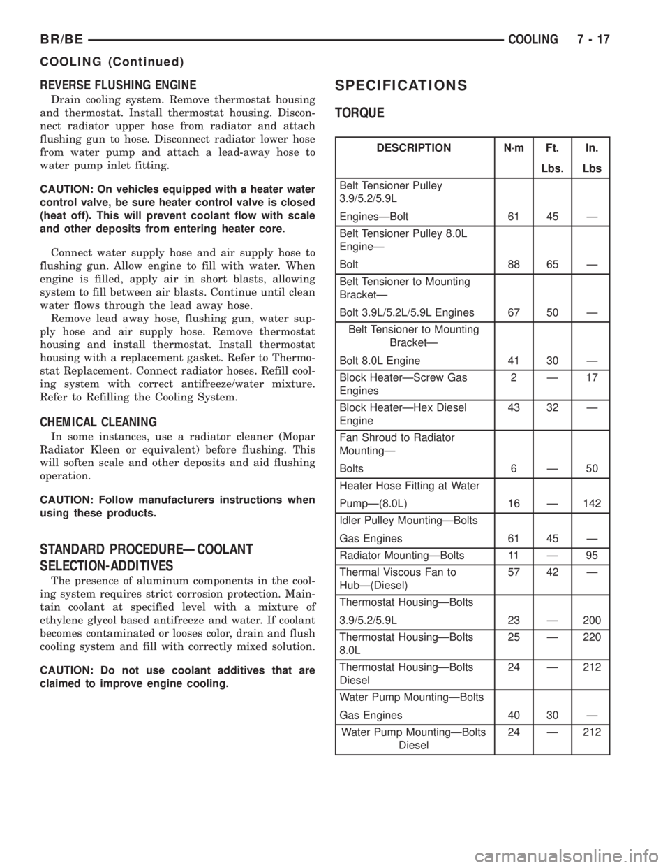
DESCRIPTION N´m Ft. In.
Lbs. Lbs
Belt Tensioner Pulley
3.9/5.2/5.9L
EnginesÐBolt 61 45 Ð
Belt Tensioner Pulley 8.0L
EngineÐ
Bolt 88 65 Ð
Belt Tensioner to Mounting
BracketÐ
Bolt 3.9L/5.2L/5.9L Engines 67 50 Ð
Belt Tensioner to Mounting
BracketÐ
Bolt 8.0L Engine 41 30 Ð
Block HeaterÐScrew Gas
Engines2Ð17
Block HeaterÐHex Diesel
Engine43 32 Ð
Fan Shroud to Radiator
MountingÐ
Bolts 6 Ð 50
Heater Hose Fitting at Water
PumpÐ(8.0L) 16 Ð 142
Idler Pulley MountingÐBolts
Gas Engines 61 45 Ð
Radiator MountingÐBolts 11 Ð 95
Thermal Viscous Fan to
HubÐ(Diesel)57 42 Ð
Thermostat HousingÐBolts
3.9/5.2/5.9L 23 Ð 200
Thermostat HousingÐBolts
8.0L25 Ð 220
Thermostat HousingÐBolts
Diesel24 Ð 212
Water Pump MountingÐBolts
Gas Engines 40 30 Ð
Water Pump MountingÐBolts
Diesel24 Ð 212
BR/BECOOLING 7 - 17
COOLING (Continued)
Page 375 of 2889
DIAGNOSIS AND TESTING.................63
RADIATOR COOLANT FLOW..............63
REMOVAL..............................63
CLEANING..............................65
INSPECTION............................65
INSTALLATION...........................65
RADIATOR PRESSURE CAP
DESCRIPTION...........................65
OPERATION.............................65
DIAGNOSIS AND TESTING.................66
RADIATOR CAP-TO-FILLER NECK SEAL.....66
RADIATOR CAP........................66
CLEANING..............................66
INSPECTION............................66
WATER PUMP - 3.9L/5.2L/5.9L
DESCRIPTION...........................67
OPERATION.............................67
DIAGNOSIS AND TESTING.................67
WATER PUMP.........................67
REMOVAL..............................67
CLEANING..............................69INSPECTION............................69
INSTALLATION...........................70
WATER PUMP - 8.0L
DIAGNOSIS AND TESTING.................70
WATER PUMP.........................70
REMOVAL..............................70
CLEANING..............................72
INSPECTION............................72
INSTALLATION...........................72
WATER PUMP - 5.9L DIESEL
DESCRIPTION...........................73
OPERATION.............................73
DIAGNOSIS AND TESTING.................73
WATER PUMP.........................73
REMOVAL..............................73
CLEANING..............................73
INSPECTION............................73
INSTALLATION...........................74
WATER PUMP INLET TUBE - 3.9L/5.2L/5.9L
REMOVAL..............................74
INSTALLATION...........................77
COOLANT
DESCRIPTION
ETHYLENE-GLYCOL MIXTURES
CAUTION: Richer antifreeze mixtures cannot be
measured with normal field equipment and can
cause problems associated with 100 percent ethyl-
ene-glycol.
The required ethylene-glycol (antifreeze) and water
mixture depends upon the climate and vehicle oper-
ating conditions. The recommended mixture of 50/50
ethylene-glycol and water will provide protection
against freezing to -37 deg. C (-35 deg. F). The anti-
freeze concentrationmust alwaysbe a minimum of
44 percent, year-round in all climates.If percentage
is lower than 44 percent, engine parts may be
eroded by cavitation, and cooling system com-
ponents may be severely damaged by corrosion.
Maximum protection against freezing is provided
with a 68 percent antifreeze concentration, which
prevents freezing down to -67.7 deg. C (-90 deg. F). A
higher percentage will freeze at a warmer tempera-
ture. Also, a higher percentage of antifreeze can
cause the engine to overheat because the specific
heat of antifreeze is lower than that of water.
Use of 100 percent ethylene-glycol will cause for-
mation of additive deposits in the system, as the cor-
rosion inhibitive additives in ethylene-glycol require
the presence of water to dissolve. The deposits act as
insulation, causing temperatures to rise to as high as
149 deg. C (300) deg. F). This temperature is hot
enough to melt plastic and soften solder. Theincreased temperature can result in engine detona-
tion. In addition, 100 percent ethylene-glycol freezes
at 22 deg. C (-8 deg. F ).
PROPYLENE-GLYCOL MIXTURES
It's overall effective temperature range is smaller
than that of ethylene-glycol. The freeze point of 50/50
propylene-glycol and water is -32 deg. C (-26 deg. F).
5 deg. C higher than ethylene-glycol's freeze point.
The boiling point (protection against summer boil-
over) of propylene-glycol is 125 deg. C (257 deg. F )
at 96.5 kPa (14 psi), compared to 128 deg. C (263
deg. F) for ethylene-glycol. Use of propylene-glycol
can result in boil-over or freeze-up on a cooling sys-
tem designed for ethylene-glycol. Propylene glycol
also has poorer heat transfer characteristics than
ethylene glycol. This can increase cylinder head tem-
peratures under certain conditions.
Propylene-glycol/ethylene-glycol Mixtures can cause
the destabilization of various corrosion inhibitors,
causing damage to the various cooling system compo-
nents. Also, once ethylene-glycol and propylene-glycol
based coolants are mixed in the vehicle, conventional
methods of determining freeze point will not be accu-
rate. Both the refractive index and specific gravity dif-
fer between ethylene glycol and propylene glycol.
OPERATION
Coolant flows through the engine block absorbing the
heat from the engine, then flows to the radiator where
the cooling fins in the radiator transfers the heat from
the coolant to the atmosphere. During cold weather the
ethylene-glycol coolant prevents water present in the
cooling system from freezing within temperatures indi-
cated by mixture ratio of coolant to water.
7 - 40 ENGINEBR/BE
Page 401 of 2889
tracts and creates a vacuum in the cooling system.
This causes the vacuum valve to open and coolant in
the reserve/overflow tank to be drawn through its
connecting hose into radiator. If the vacuum valve is
stuck shut, the radiator hoses will collapse on cool-
down. Clean the vent valve (Fig. 43).
DIAGNOSIS AND TESTINGÐRADIATOR
CAP-TO-FILLER NECK SEAL
The pressure cap upper gasket (seal) pressure
relief can be tested by removing overflow hose from
radiator filler neck nipple. Attach hose of pressure
tester tool 7700 (or equivalent) to nipple. It will be
necessary to disconnect hose from its adapter for
filler neck. Pump air into radiator. The pressure cap
upper gasket should relieve at 69-124 kPa (10-18 psi)
and hold pressure at a minimum of 55 kPa (8 psi).
WARNING: THE WARNING WORDS ÐDO NOT
OPEN HOTÐ ON RADIATOR PRESSURE CAP, ARE
A SAFETY PRECAUTION. WHEN HOT, PRESSURE
BUILDS UP IN COOLING SYSTEM. TO PREVENT
SCALDING OR INJURY, RADIATOR CAP SHOULD
NOT BE REMOVED WHILE SYSTEM IS HOT AND/OR
UNDER PRESSURE.
Do not remove radiator cap at any timeexceptfor
the following purposes:
²Check and adjust antifreeze freeze point
²Refill system with new antifreeze
²Conducting service procedures
²Checking for vacuum leaks
WARNING: IF VEHICLE HAS BEEN RUN RECENTLY,
WAIT AT LEAST 15 MINUTES BEFORE REMOVING
RADIATOR CAP. WITH A RAG, SQUEEZE RADIATOR
UPPER HOSE TO CHECK IF SYSTEM IS UNDER
PRESSURE. PLACE A RAG OVER CAP AND WITH-
OUT PUSHING CAP DOWN, ROTATE IT COUNTER-
CLOCKWISE TO FIRST STOP. ALLOW FLUID TO
ESCAPE THROUGH THE COOLANT RESERVE/
OVERFLOW HOSE INTO RESERVE/OVERFLOW
TANK. SQUEEZE RADIATOR UPPER HOSE TO
DETERMINE WHEN PRESSURE HAS BEEN
RELEASED. WHEN COOLANT AND STEAM STOP
BEING PUSHED INTO TANK AND SYSTEM PRES-
SURE DROPS, REMOVE RADIATOR CAP COM-
PLETELY.
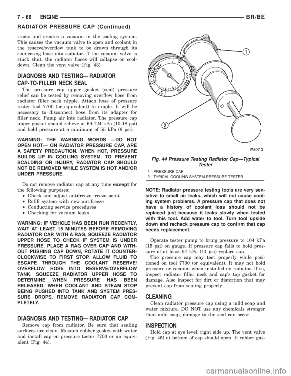
DIAGNOSIS AND TESTINGÐRADIATOR CAP
Remove cap from radiator. Be sure that sealing
surfaces are clean. Moisten rubber gasket with water
and install cap on pressure tester 7700 or an equiv-
alent (Fig. 44).NOTE: Radiator pressure testing tools are very sen-
sitive to small air leaks, which will not cause cool-
ing system problems. A pressure cap that does not
have a history of coolant loss should not be
replaced just because it leaks slowly when tested
with this tool. Add water to tool. Turn tool upside
down and recheck pressure cap to confirm that cap
needs replacement.
Operate tester pump to bring pressure to 104 kPa
(15 psi) on gauge. If pressure cap fails to hold pres-
sure of at least 97 kPa (14 psi) replace cap.
The pressure cap may test properly while posi-
tioned on tool 7700 (or equivalent). It may not hold
pressure or vacuum when installed on radiator. If so,
inspect radiator filler neck and cap's top gasket for
damage. Also inspect for dirt or distortion that may
prevent cap from sealing properly.
CLEANING
Clean radiator pressure cap using a mild soap and
water mixture. DO NOT use any chemicals stronger
than mild soap, damage to the seal can occur .
INSPECTION
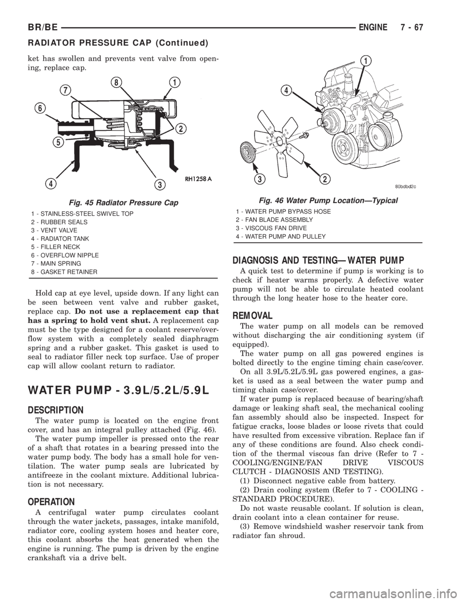
Hold cap at eye level, right side up. The vent valve
(Fig. 45) at bottom of cap should open. If rubber gas-
Fig. 44 Pressure Testing Radiator CapÐTypical
Tester
1 - PRESSURE CAP
2 - TYPICAL COOLING SYSTEM PRESSURE TESTER
7 - 66 ENGINEBR/BE
RADIATOR PRESSURE CAP (Continued)
Page 402 of 2889
ket has swollen and prevents vent valve from open-
ing, replace cap.
Hold cap at eye level, upside down. If any light can
be seen between vent valve and rubber gasket,
replace cap.Do not use a replacement cap that
has a spring to hold vent shut.A replacement cap
must be the type designed for a coolant reserve/over-
flow system with a completely sealed diaphragm
spring and a rubber gasket. This gasket is used to
seal to radiator filler neck top surface. Use of proper
cap will allow coolant return to radiator.
WATER PUMP - 3.9L/5.2L/5.9L
DESCRIPTION
The water pump is located on the engine front
cover, and has an integral pulley attached (Fig. 46).
The water pump impeller is pressed onto the rear
of a shaft that rotates in a bearing pressed into the
water pump body. The body has a small hole for ven-
tilation. The water pump seals are lubricated by
antifreeze in the coolant mixture. Additional lubrica-
tion is not necessary.
OPERATION
A centrifugal water pump circulates coolant
through the water jackets, passages, intake manifold,
radiator core, cooling system hoses and heater core,
this coolant absorbs the heat generated when the
engine is running. The pump is driven by the engine
crankshaft via a drive belt.
DIAGNOSIS AND TESTINGÐWATER PUMP
A quick test to determine if pump is working is to
check if heater warms properly. A defective water
pump will not be able to circulate heated coolant
through the long heater hose to the heater core.
REMOVAL
The water pump on all models can be removed
without discharging the air conditioning system (if
equipped).
The water pump on all gas powered engines is
bolted directly to the engine timing chain case/cover.
On all 3.9L/5.2L/5.9L gas powered engines, a gas-
ket is used as a seal between the water pump and
timing chain case/cover.
If water pump is replaced because of bearing/shaft
damage or leaking shaft seal, the mechanical cooling
fan assembly should also be inspected. Inspect for
fatigue cracks, loose blades or loose rivets that could
have resulted from excessive vibration. Replace fan if
any of these conditions are found. Also check condi-
tion of the thermal viscous fan drive (Refer to 7 -
COOLING/ENGINE/FAN DRIVE VISCOUS
CLUTCH - DIAGNOSIS AND TESTING).
(1) Disconnect negative cable from battery.
(2) Drain cooling system (Refer to 7 - COOLING -
STANDARD PROCEDURE).
Do not waste reusable coolant. If solution is clean,
drain coolant into a clean container for reuse.
(3) Remove windshield washer reservoir tank from
radiator fan shroud.
Fig. 45 Radiator Pressure Cap
1 - STAINLESS-STEEL SWIVEL TOP
2 - RUBBER SEALS
3 - VENT VALVE
4 - RADIATOR TANK
5 - FILLER NECK
6 - OVERFLOW NIPPLE
7 - MAIN SPRING
8 - GASKET RETAINER
Fig. 46 Water Pump LocationÐTypical
1 - WATER PUMP BYPASS HOSE
2 - FAN BLADE ASSEMBLY
3 - VISCOUS FAN DRIVE
4 - WATER PUMP AND PULLEY
BR/BEENGINE 7 - 67
RADIATOR PRESSURE CAP (Continued)
Page 408 of 2889
(11) Install fan shroud to radiator. Tighten bolts to
6 N´m (50 in. lbs.) torque.
(12) Install fan blade/viscous fan drive assembly to
water pump shaft.
(13) Fill cooling system (Refer to 7 - COOLING -
STANDARD PROCEDURE).
(14) Connect negative battery cable.
(15) Start and warm the engine. Check for leaks.
WATER PUMP - 5.9L DIESEL
DESCRIPTION
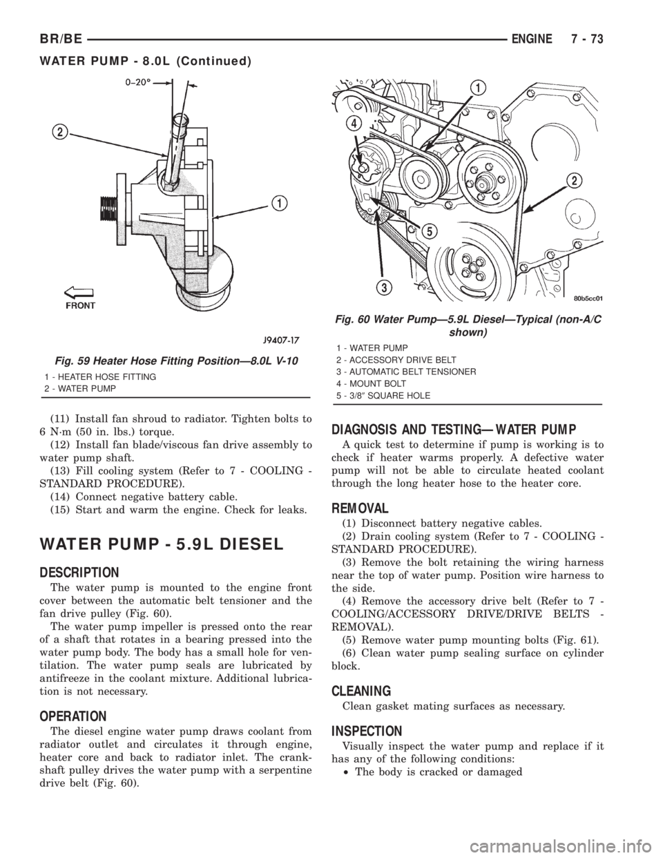
The water pump is mounted to the engine front
cover between the automatic belt tensioner and the
fan drive pulley (Fig. 60).
The water pump impeller is pressed onto the rear
of a shaft that rotates in a bearing pressed into the
water pump body. The body has a small hole for ven-
tilation. The water pump seals are lubricated by
antifreeze in the coolant mixture. Additional lubrica-
tion is not necessary.
OPERATION
The diesel engine water pump draws coolant from
radiator outlet and circulates it through engine,
heater core and back to radiator inlet. The crank-
shaft pulley drives the water pump with a serpentine
drive belt (Fig. 60).
DIAGNOSIS AND TESTINGÐWATER PUMP
A quick test to determine if pump is working is to
check if heater warms properly. A defective water
pump will not be able to circulate heated coolant
through the long heater hose to the heater core.
REMOVAL
(1) Disconnect battery negative cables.
(2) Drain cooling system (Refer to 7 - COOLING -
STANDARD PROCEDURE).
(3) Remove the bolt retaining the wiring harness
near the top of water pump. Position wire harness to
the side.
(4) Remove the accessory drive belt (Refer to 7 -
COOLING/ACCESSORY DRIVE/DRIVE BELTS -
REMOVAL).
(5) Remove water pump mounting bolts (Fig. 61).
(6) Clean water pump sealing surface on cylinder
block.
CLEANING
Clean gasket mating surfaces as necessary.
INSPECTION
Visually inspect the water pump and replace if it
has any of the following conditions:
²The body is cracked or damaged
Fig. 59 Heater Hose Fitting PositionÐ8.0L V-10
1 - HEATER HOSE FITTING
2 - WATER PUMP
Fig. 60 Water PumpÐ5.9L DieselÐTypical (non-A/C
shown)
1 - WATER PUMP
2 - ACCESSORY DRIVE BELT
3 - AUTOMATIC BELT TENSIONER
4 - MOUNT BOLT
5 - 3/89SQUARE HOLE
BR/BEENGINE 7 - 73
WATER PUMP - 8.0L (Continued)
Page 412 of 2889
REMOVALÐWATER PUMP BYPASS HOSE
WITHOUT AIR CONDITIONING
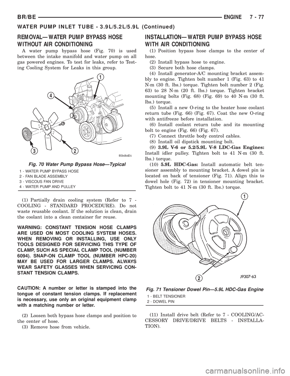
A water pump bypass hose (Fig. 70) is used
between the intake manifold and water pump on all
gas powered engines. To test for leaks, refer to Test-
ing Cooling System for Leaks in this group.
(1) Partially drain cooling system (Refer to 7 -
COOLING - STANDARD PROCEDURE). Do not
waste reusable coolant. If the solution is clean, drain
the coolant into a clean container for reuse.
WARNING: CONSTANT TENSION HOSE CLAMPS
ARE USED ON MOST COOLING SYSTEM HOSES.
WHEN REMOVING OR INSTALLING, USE ONLY
TOOLS DESIGNED FOR SERVICING THIS TYPE OF
CLAMP, SUCH AS SPECIAL CLAMP TOOL (NUMBER
6094). SNAP-ON CLAMP TOOL (NUMBER HPC-20)
MAY BE USED FOR LARGER CLAMPS. ALWAYS
WEAR SAFETY GLASSES WHEN SERVICING CON-
STANT TENSION CLAMPS.
CAUTION: A number or letter is stamped into the
tongue of constant tension clamps. If replacement
is necessary, use only an original equipment clamp
with a matching number or letter.
(2) Loosen both bypass hose clamps and position to
the center of hose.
(3) Remove hose from vehicle.
INSTALLATIONÐWATER PUMP BYPASS HOSE
WITH AIR CONDITIONING
(1) Position bypass hose clamps to the center of
hose.
(2) Install bypass hose to engine.
(3) Secure both hose clamps.
(4) Install generator-A/C mounting bracket assem-
bly to engine. Tighten bolt number 1 (Fig. 63) to 41
N´m (30 ft. lbs.) torque. Tighten bolt number 2 (Fig.
63) to 28 N´m (20 ft. lbs.) torque. Tighten bracket
mounting bolts (Fig. 68) (Fig. 69) to 40 N´m (30 ft.
lbs.) torque.
(5) Install a new O-ring to the heater hose coolant
return tube (Fig. 66) (Fig. 67). Coat the new O-ring
with antifreeze before installation.
(6) Install coolant return tube and its mounting
bolt to engine (Fig. 66) (Fig. 67).
(7) Connect throttle body control cables.
(8) Install oil dipstick mounting bolt.
(9)3.9L V-6 or 5.2/5.9L V-8 LDC-Gas Engines:
Install idler pulley. Tighten bolt to 41 N´m (30 ft.
lbs.) torque.
(10)5.9L HDC-Gas:Install automatic belt ten-
sioner assembly to mounting bracket. A dowel pin is
located on back of tensioner (Fig. 71). Align this to
dowel hole (Fig. 72) in tensioner mounting bracket.
Tighten bolt to 41 N´m (30 ft. lbs.) torque.
(11) Install drive belt (Refer to 7 - COOLING/AC-
CESSORY DRIVE/DRIVE BELTS - INSTALLA-
TION).
Fig. 71 Tensioner Dowel PinÐ5.9L HDC-Gas Engine
1 - BELT TENSIONER
2 - DOWEL PIN
Fig. 70 Water Pump Bypass HoseÐTypical
1 - WATER PUMP BYPASS HOSE
2 - FAN BLADE ASSEMBLY
3 - VISCOUS FAN DRIVE
4 - WATER PUMP AND PULLEY
BR/BEENGINE 7 - 77
WATER PUMP INLET TUBE - 3.9L/5.2L/5.9L (Continued)
Page 2830 of 2889
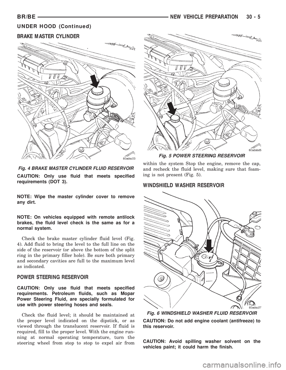
BRAKE MASTER CYLINDER
CAUTION: Only use fluid that meets specified
requirements (DOT 3).
NOTE: Wipe the master cylinder cover to remove
any dirt.
NOTE: On vehicles equipped with remote antilock
brakes, the fluid level check is the same as for a
normal system.
Check the brake master cylinder fluid level (Fig.
4). Add fluid to bring the level to the full line on the
side of the reservoir (or above the bottom of the split
ring in the primary filler hole). Be sure both primary
and secondary cavities are full to the maximum level
as indicated.
POWER STEERING RESERVOIR
CAUTION: Only use fluid that meets specified
requirements. Petroleum fluids, such as Mopar
Power Steering Fluid, are specially formulated for
use with power steering hoses and seals.
Check the fluid level; it should be maintained at
the proper level indicated on the dipstick, or as
viewed through the translucent reservoir. If fluid is
required, fill to the proper level. With the engine run-
ning at normal operating temperature, turn the
steering wheel from stop to stop to expel air fromwithin the system Stop the engine, remove the cap,
and recheck the fluid level, making sure that foam-
ing is not present (Fig. 5).
WINDSHIELD WASHER RESERVOIR
CAUTION: Do not add engine coolant (antifreeze) to
this reservoir.
CAUTION: Avoid spilling washer solvent on the
vehicles paint; it could harm the finish.
Fig. 4 BRAKE MASTER CYLINDER FLUID RESERVOIR
Fig. 5 POWER STEERING RESERVOIR
Fig. 6 WINDSHIELD WASHER FLUID RESERVOIR
BR/BENEW VEHICLE PREPARATION 30 - 5
UNDER HOOD (Continued)
Page 2831 of 2889
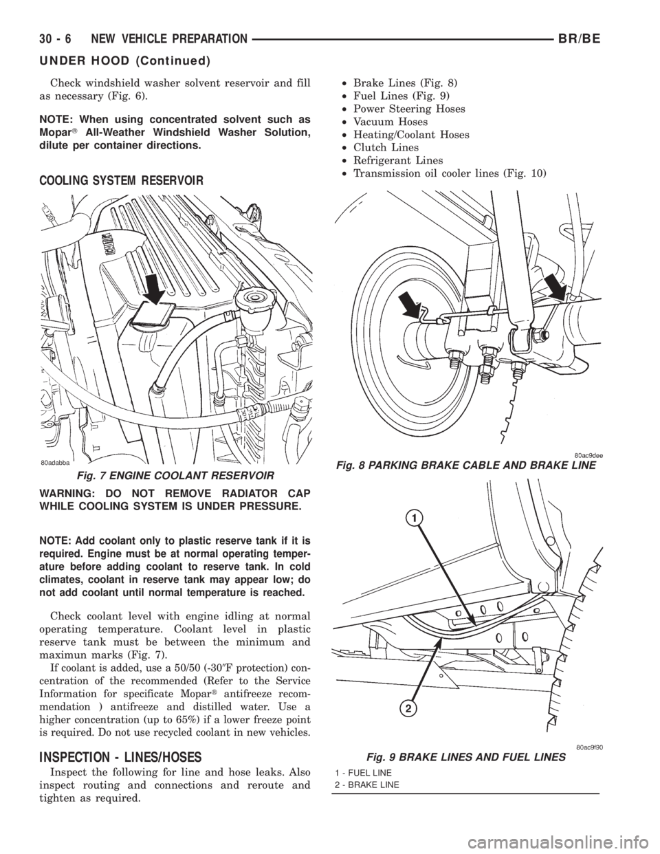
Check windshield washer solvent reservoir and fill
as necessary (Fig. 6).
NOTE: When using concentrated solvent such as
MoparTAll-Weather Windshield Washer Solution,
dilute per container directions.
COOLING SYSTEM RESERVOIR
WARNING: DO NOT REMOVE RADIATOR CAP
WHILE COOLING SYSTEM IS UNDER PRESSURE.
NOTE: Add coolant only to plastic reserve tank if it is
required. Engine must be at normal operating temper-
ature before adding coolant to reserve tank. In cold
climates, coolant in reserve tank may appear low; do
not add coolant until normal temperature is reached.
Check coolant level with engine idling at normal
operating temperature. Coolant level in plastic
reserve tank must be between the minimum and
maximun marks (Fig. 7).
If coolant is added, use a 50/50 (-309F protection) con-
centration of the recommended (Refer to the Service
Information for specificate Mopartantifreeze recom-
mendation ) antifreeze and distilled water. Use a
higher concentration (up to 65%) if a lower freeze point
is required. Do not use recycled coolant in new vehicles.
INSPECTION - LINES/HOSES
Inspect the following for line and hose leaks. Also
inspect routing and connections and reroute and
tighten as required.²Brake Lines (Fig. 8)
²Fuel Lines (Fig. 9)
²Power Steering Hoses
²Vacuum Hoses
²Heating/Coolant Hoses
²Clutch Lines
²Refrigerant Lines
²Transmission oil cooler lines (Fig. 10)
Fig. 7 ENGINE COOLANT RESERVOIRFig. 8 PARKING BRAKE CABLE AND BRAKE LINE
Fig. 9 BRAKE LINES AND FUEL LINES
1 - FUEL LINE
2 - BRAKE LINE
30 - 6 NEW VEHICLE PREPARATIONBR/BE
UNDER HOOD (Continued)