fold seats DODGE RAM 2001 Service Repair Manual
[x] Cancel search | Manufacturer: DODGE, Model Year: 2001, Model line: RAM, Model: DODGE RAM 2001Pages: 2889, PDF Size: 68.07 MB
Page 695 of 2889
(4) Reinstall the trim onto the B-pillar. (Refer to
23 - BODY/INTERIOR/B-PILLAR TRIM - INSTAL-
LATION).
(5) Position the shoulder belt turning loop onto the
height adjuster.
(6) Install and tighten the screw that secures the
shoulder belt turning loop to the height adjuster.
Tighten the screw to 30 N´m (22 ft. lbs.).
(7) Fold and snap the cover over the front shoulder
belt turning loop to conceal the screw that secures
the turning loop to the height adjuster.
(8) Install and tighten the screw that secures the
lower seat belt anchor plate to the floor panel near
the base of the B-pillar. Tighten the screw to 40 N´m
(29 ft. lbs.).
INSTALLATION - CLUB/QUAD CAB
The front seat shoulder belt and retractor are inte-
gral to the driver and passenger front seat backs on
club cab and quad cab models.
WARNING: DURING AND FOLLOWING ANY SEAT
BELT SERVICE, CAREFULLY INSPECT ALL SEAT
BELTS, BUCKLES, MOUNTING HARDWARE, AND
RETRACTORS FOR PROPER INSTALLATION,
OPERATION, OR DAMAGE. REPLACE ANY BELT
THAT IS CUT, FRAYED, OR TORN. STRAIGHTEN
ANY BELT THAT IS TWISTED. TIGHTEN ANY
LOOSE FASTENERS. REPLACE ANY BELT THAT
HAS A DAMAGED OR INOPERATIVE BUCKLE OR
RETRACTOR. REPLACE ANY BELT THAT HAS A
BENT OR DAMAGED LATCH PLATE OR ANCHOR
PLATE. NEVER ATTEMPT TO REPAIR A SEAT BELT
COMPONENT. ALWAYS REPLACE DAMAGED OR
FAULTY SEAT BELT COMPONENTS WITH THE COR-
RECT, NEW AND UNUSED REPLACEMENT PARTS
LISTED IN THE MOPAR PARTS CATALOG.
(1) Position the front shoulder belt and retractor
onto the seat back frame.
(2) Install and tighten the two screws that secure
the seat belt retractor to the seat back frame (Fig.
16). Tighten the screws to 16 N´m (12 ft. lbs.).
(3) Position the retractor cover onto the seat back
frame.
(4) Install and tighten the screws that secure the
retractor cover to the seat back frame. Tighten the
screws to 2 N´m (17 in. lbs.).
(5) Reinstall the trim cover onto the front seat
back frame. (Refer to 23 - BODY/SEATS/SEAT BACK
COVER - INSTALLATION).
FRONT SEAT BELT BUCKLE
REMOVAL
WARNING: DURING AND FOLLOWING ANY SEAT
BELT SERVICE, CAREFULLY INSPECT ALL SEAT
BELTS, BUCKLES, MOUNTING HARDWARE, AND
RETRACTORS FOR PROPER INSTALLATION,
OPERATION, OR DAMAGE. REPLACE ANY BELT
THAT IS CUT, FRAYED, OR TORN. STRAIGHTEN
ANY BELT THAT IS TWISTED. TIGHTEN ANY
LOOSE FASTENERS. REPLACE ANY BELT THAT
HAS A DAMAGED OR INOPERATIVE BUCKLE OR
RETRACTOR. REPLACE ANY BELT THAT HAS A
BENT OR DAMAGED LATCH PLATE OR ANCHOR
PLATE. NEVER ATTEMPT TO REPAIR A SEAT BELT
COMPONENT. ALWAYS REPLACE DAMAGED OR
FAULTY SEAT BELT COMPONENTS WITH THE COR-
RECT, NEW AND UNUSED REPLACEMENT PARTS
LISTED IN THE MOPAR PARTS CATALOG.
(1) Move the front seat to its most forward position
for easiest access to the front seat belt buckle
anchors.
(2) Tilt both front seat backs forward far enough to
access the seat belt buckle anchor screws.
(3) On the driver's side only, disconnect the body
wire harness connector for the seat belt switch from
the seat belt switch pigtail wire connector on the seat
belt buckle.
(4) Remove the screw that secures the seat belt
buckle to the anchor on the seat cushion frame.
(5) Remove the front seat belt buckle from the seat
cushion frame.
INSTALLATION
WARNING: DURING AND FOLLOWING ANY SEAT
BELT SERVICE, CAREFULLY INSPECT ALL SEAT
BELTS, BUCKLES, MOUNTING HARDWARE, AND
RETRACTORS FOR PROPER INSTALLATION,
OPERATION, OR DAMAGE. REPLACE ANY BELT
THAT IS CUT, FRAYED, OR TORN. STRAIGHTEN
ANY BELT THAT IS TWISTED. TIGHTEN ANY
LOOSE FASTENERS. REPLACE ANY BELT THAT
HAS A DAMAGED OR INOPERATIVE BUCKLE OR
RETRACTOR. REPLACE ANY BELT THAT HAS A
BENT OR DAMAGED LATCH PLATE OR ANCHOR
PLATE. NEVER ATTEMPT TO REPAIR A SEAT BELT
COMPONENT. ALWAYS REPLACE DAMAGED OR
FAULTY SEAT BELT COMPONENTS WITH THE COR-
RECT, NEW AND UNUSED REPLACEMENT PARTS
LISTED IN THE MOPAR PARTS CATALOG.
(1) Position the front seat belt buckle onto the seat
cushion frame.
8O - 20 RESTRAINTSBR/BE
FRONT SEAT BELT & RETRACTOR (Continued)
Page 702 of 2889
(2) Install and tighten the screw that secures the
retractor to the quarter inner panel. Tighten the
screw to 40 N´m (29 ft. lbs.).
(3) Engage the rear seat shoulder belt turning loop
and lower seat belt anchor plate with the quarter
trim panel.
(4) Reinstall the trim onto the quarter inner panel.
(Refer to 23 - BODY/INTERIOR/QUARTER TRIM
PANEL - INSTALLATION).
(5) Position the shoulder belt turning loop onto the
quarter inner panel near the top of the C-pillar.
(6) Install and tighten the screw that secures the
shoulder belt turning loop to the quarter inner panel.
Tighten the screw to 40 N´m (29 ft. lbs.).
(7) Fold and snap the cover over the rear shoulder
belt turning loop to conceal the screw that secures
the turning loop to the quarter inner panel.
(8) Position the lower seat belt anchor plate onto
the quarter inner panel near the base of the C-pillar.
(9) Install and tighten the screw that secures the
lower seat belt anchor plate to the quarter inner
panel near the base of the C-pillar. Tighten the screw
to 40 N´m (29 ft. lbs.).
(10) Reinstall the trim cover onto the door sill.
(Refer to 23 - BODY/INTERIOR/DOOR SILL TRIM -
INSTALLATION).
(11) Reinstall the rear seat into the passenger
compartment. (Refer to 23 - BODY/SEATS/REAR
SEAT - INSTALLATION).
REAR SEAT BELT BUCKLE
REMOVAL
WARNING: DURING AND FOLLOWING ANY SEAT
BELT SERVICE, CAREFULLY INSPECT ALL SEAT
BELTS, BUCKLES, MOUNTING HARDWARE, AND
RETRACTORS FOR PROPER INSTALLATION,
OPERATION, OR DAMAGE. REPLACE ANY BELT
THAT IS CUT, FRAYED, OR TORN. STRAIGHTEN
ANY BELT THAT IS TWISTED. TIGHTEN ANY
LOOSE FASTENERS. REPLACE ANY BELT THAT
HAS A DAMAGED OR INOPERATIVE BUCKLE OR
RETRACTOR. REPLACE ANY BELT THAT HAS A
BENT OR DAMAGED LATCH PLATE OR ANCHOR
PLATE. NEVER ATTEMPT TO REPAIR A SEAT BELT
COMPONENT. ALWAYS REPLACE DAMAGED OR
FAULTY SEAT BELT COMPONENTS WITH THE COR-
RECT, NEW AND UNUSED REPLACEMENT PARTS
LISTED IN THE MOPAR PARTS CATALOG.
(1) Disengage the rear seat latch by pulling the
release handle on the underside of the rear seat
cushion.(2) Fold the rear seat unit up and back against the
cab back panel (stowed position) for access to the
rear seat belt buckle anchors.
(3) Reach through the opening between the rear
seat back and the floor panel to access and remove
the nut that secures the rear seat belt buckle/buckle
unit (right side) or lap belt/buckle unit (left side)
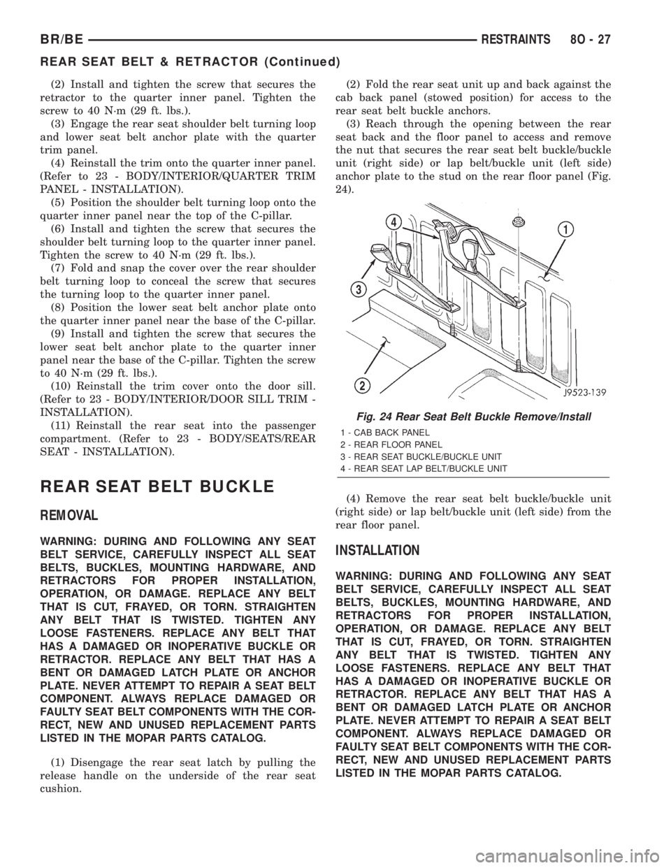
anchor plate to the stud on the rear floor panel (Fig.
24).
(4) Remove the rear seat belt buckle/buckle unit
(right side) or lap belt/buckle unit (left side) from the
rear floor panel.INSTALLATION
WARNING: DURING AND FOLLOWING ANY SEAT
BELT SERVICE, CAREFULLY INSPECT ALL SEAT
BELTS, BUCKLES, MOUNTING HARDWARE, AND
RETRACTORS FOR PROPER INSTALLATION,
OPERATION, OR DAMAGE. REPLACE ANY BELT
THAT IS CUT, FRAYED, OR TORN. STRAIGHTEN
ANY BELT THAT IS TWISTED. TIGHTEN ANY
LOOSE FASTENERS. REPLACE ANY BELT THAT
HAS A DAMAGED OR INOPERATIVE BUCKLE OR
RETRACTOR. REPLACE ANY BELT THAT HAS A
BENT OR DAMAGED LATCH PLATE OR ANCHOR
PLATE. NEVER ATTEMPT TO REPAIR A SEAT BELT
COMPONENT. ALWAYS REPLACE DAMAGED OR
FAULTY SEAT BELT COMPONENTS WITH THE COR-
RECT, NEW AND UNUSED REPLACEMENT PARTS
LISTED IN THE MOPAR PARTS CATALOG.
Fig. 24 Rear Seat Belt Buckle Remove/Install
1 - CAB BACK PANEL
2 - REAR FLOOR PANEL
3 - REAR SEAT BUCKLE/BUCKLE UNIT
4 - REAR SEAT LAP BELT/BUCKLE UNIT
BR/BERESTRAINTS 8O - 27
REAR SEAT BELT & RETRACTOR (Continued)
Page 1228 of 2889
CAUTION: When tightening the rocker arm bolts,
make sure the piston in that cylinder is NOT at
TDC. Contact between the valves and piston could
occur.
(6) Install push rods and rocker arm assemblies in
their original position. Tighten the bolts to 28 N´m
(21 ft. lbs.) torque.
(7) Install the intake manifold (Refer to 9 -
ENGINE/MANIFOLDS/INTAKE MANIFOLD -
INSTALLATION) and throttle body assembly.
(8) Install exhaust manifolds (Refer to 9 -
ENGINE/MANIFOLDS/EXHAUST MANIFOLD -
INSTALLATION).
(9) If required, adjust spark plugs to specifications.
Install the plugs and tighten to 41 N´m (30 ft. lbs.)
torque.
(10) Install coil wire.
(11) Connect heat indicator sending unit wire.
(12) Connect the heater hoses and bypass hose.
(13) Install distributor cap and wires.
(14) Connect the accelerator linkage and if so
equipped, the speed control and transmission kick-
down cables.
(15) Install the fuel supply line (Refer to 14 -
FUEL SYSTEM/FUEL DELIVERY/QUICK CON-
NECT FITTING - STANDARD PROCEDURE).
(16) Install the generator and drive belt (Refer to 7
- COOLING/ACCESSORY DRIVE/DRIVE BELTS -
INSTALLATION). Tighten generator mounting bolt
to 41 N´m (30 ft. lbs.) torque. Tighten the adjusting
strap bolt to 23 N´m (200 in. lbs.) torque.
(17) Install the intake manifold-to-generator
bracket support rod. Tighten the bolts.
(18) Place the cylinder head cover gaskets in posi-
tion and install cylinder head covers (Refer to 9 -
ENGINE/CYLINDER HEAD/CYLINDER HEAD
COVER(S) - INSTALLATION).
(19) Install closed crankcase ventilation system.
(20) Connect the evaporation control system.
(21) Install the air cleaner.
(22) Fill cooling system (Refer to 7 - COOLING -
STANDARD PROCEDURE).
(23) Connect the negative cable to the battery.
(24) Start engine check for leaks.
CYLINDER HEAD COVER(S)
REMOVAL
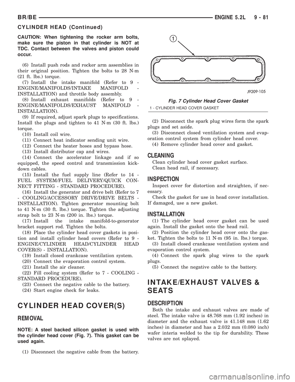
NOTE: A steel backed silicon gasket is used with
the cylinder head cover (Fig. 7). This gasket can be
used again.
(1) Disconnect the negative cable from the battery.(2) Disconnect the spark plug wires form the spark
plugs and set aside.
(3) Disconnect closed ventilation system and evap-
oration control system from cylinder head cover.
(4) Remove cylinder head cover and gasket.
CLEANING
Clean cylinder head cover gasket surface.
Clean head rail, if necessary.
INSPECTION
Inspect cover for distortion and straighten, if nec-
essary.
Check the gasket for use in head cover installation.
If damaged, use a new gasket.
INSTALLATION
(1) The cylinder head cover gasket can be used
again. Install the gasket onto the head rail.
(2) Position the cylinder head cover onto the gas-
ket. Tighten the bolts to 11 N´m (95 in. lbs.) torque.
(3) Install closed crankcase ventilation system and
evaporation control system.
(4) Connect the spark plug wires to the spark
plugs.
(5) Connect the negative cable to the battery.
INTAKE/EXHAUST VALVES &
SEATS
DESCRIPTION
Both the intake and exhaust valves are made of
steel. The intake valve is 48.768 mm (1.92 inches) in
diameter and the exhaust valve is 41.148 mm (1.62
inches) in diameter and has a 2.032 mm (0.080 inch)
wafer interia welded to the tip for durability. These
valves are not splayed.
Fig. 7 Cylinder Head Cover Gasket
1 - CYLINDER HEAD COVER GASKET
BR/BEENGINE 5.2L 9 - 81
CYLINDER HEAD (Continued)
Page 1267 of 2889
CONDITION POSSIBLE CAUSES CORRECTION
7. Intake manifold vacuum leak 7. Inspect intake manifold gasket
and vacuum hoses (Refer to 9 -
ENGINE/MANIFOLDS/INTAKE
MANIFOLD - DIAGNOSIS AND
TESTING).
ENGINE MISSES ON
ACCELERATION1. Worn or incorrectly gapped spark
plugs1. Replace spark plugs or clean and
set gap. (Refer to 8 - ELECTRICAL/
IGNITION CONTROL/SPARK PLUG
- CLEANING)
2. Spark plug cables defective or
crossed2. Replace or rewire secondary
ignition cables. (Refer to 8 -
ELECTRICAL/IGNITION CONTROL/
SPARK PLUG CABLE - REMOVAL)
3. Dirt in fuel system 3. Clean fuel system
4. Burned, warped or pitted valves 4. Install new valves
5. Faulty coil 5. Test and replace as necessary
(Refer to 8 - ELECTRICAL/
IGNITION CONTROL/IGNITION
COIL - REMOVAL)
DIAGNOSIS AND TESTINGÐ MECHANICAL
ENGINE MECHANICAL DIAGNOSIS CHART
CONDITION POSSIBLE CAUSES CORRECTION
NOISY VALVES/LIFTERS 1. High or low oil level in crankcase 1. Check for correct oil level. Adjust
oil level by draining or adding as
needed
2. Thin or diluted oil 2. Change oil. (Refer to 9 -
ENGINE/LUBRICATION/OIL -
STANDARD PROCEDURE)
3. Low oil pressure 3. Check engine oil level. If ok,
Perform oil pressure test. (Refer to
9 - ENGINE/LUBRICATION -
DIAGNOSIS AND TESTING) for
engine oil pressure test/
specifications
4. Dirt in tappets/lash adjusters 4. Clean/replace hydraulic
tappets/lash adjusters
5. Bent push rod(s) 5. Install new push rods
6. Worn rocker arms 6. Inspect oil supply to rocker arms
and replace worn arms as needed
7. Worn tappets/lash adjusters 7. Install new hydraulic tappets/lash
adjusters
8. Worn valve guides 8. Inspect all valve guides and
replace as necessary
9. Excessive runout of valve seats
or valve faces9. Grind valves and seats
9 - 120 ENGINE 5.9LBR/BE
ENGINE 5.9L (Continued)
Page 1285 of 2889
(9) If required, adjust spark plugs to specifications.
Install the plugs and tighten to 41 N´m (30 ft. lbs.)
torque.
(10) Install coil wire.
(11) Connect heat indicator sending unit wire.
(12) Connect the heater hoses and bypass hose.
(13) Install distributor cap and wires.
(14) Connect the accelerator linkage and if so
equipped, the speed control and transmission kick-
down cables.
(15) Install the fuel supply line (Refer to 14 -
FUEL SYSTEM/FUEL DELIVERY/QUICK CON-
NECT FITTING - STANDARD PROCEDURE).
(16) Install the generator and drive belt (Refer to 7
- COOLING/ACCESSORY DRIVE/DRIVE BELTS -
INSTALLATION). Tighten generator mounting bolt
to 41 N´m (30 ft. lbs.) torque. Tighten the adjusting
strap bolt to 23 N´m (200 in. lbs.) torque.
(17) Install the intake manifold-to-generator
bracket support rod. Tighten the bolts.
(18) Place the cylinder head cover gaskets in posi-
tion and install cylinder head covers (Refer to 9 -
ENGINE/CYLINDER HEAD/CYLINDER HEAD
COVER(S) - INSTALLATION).
(19) Install closed crankcase ventilation system.
(20) Connect the evaporation control system.
(21) Install the air cleaner.
(22) Fill cooling system (Refer to 7 - COOLING -
STANDARD PROCEDURE).
(23) Connect the negative cable to the battery.
(24) Start engine check for leaks.
CYLINDER HEAD COVER(S)
REMOVAL
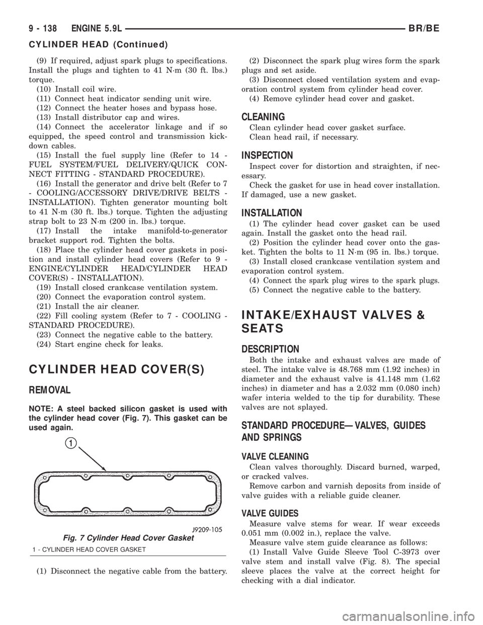
NOTE: A steel backed silicon gasket is used with
the cylinder head cover (Fig. 7). This gasket can be
used again.
(1) Disconnect the negative cable from the battery.(2) Disconnect the spark plug wires form the spark
plugs and set aside.
(3) Disconnect closed ventilation system and evap-
oration control system from cylinder head cover.
(4) Remove cylinder head cover and gasket.
CLEANING
Clean cylinder head cover gasket surface.
Clean head rail, if necessary.
INSPECTION
Inspect cover for distortion and straighten, if nec-
essary.
Check the gasket for use in head cover installation.
If damaged, use a new gasket.
INSTALLATION
(1) The cylinder head cover gasket can be used
again. Install the gasket onto the head rail.
(2) Position the cylinder head cover onto the gas-
ket. Tighten the bolts to 11 N´m (95 in. lbs.) torque.
(3) Install closed crankcase ventilation system and
evaporation control system.
(4)
Connect the spark plug wires to the spark plugs.
(5) Connect the negative cable to the battery.
INTAKE/EXHAUST VALVES &
SEATS
DESCRIPTION
Both the intake and exhaust valves are made of
steel. The intake valve is 48.768 mm (1.92 inches) in
diameter and the exhaust valve is 41.148 mm (1.62
inches) in diameter and has a 2.032 mm (0.080 inch)
wafer interia welded to the tip for durability. These
valves are not splayed.
STANDARD PROCEDUREÐVALVES, GUIDES
AND SPRINGS
VALVE CLEANING
Clean valves thoroughly. Discard burned, warped,
or cracked valves.
Remove carbon and varnish deposits from inside of
valve guides with a reliable guide cleaner.
VALVE GUIDES
Measure valve stems for wear. If wear exceeds
0.051 mm (0.002 in.), replace the valve.
Measure valve stem guide clearance as follows:
(1) Install Valve Guide Sleeve Tool C-3973 over
valve stem and install valve (Fig. 8). The special
sleeve places the valve at the correct height for
checking with a dial indicator.
Fig. 7 Cylinder Head Cover Gasket
1 - CYLINDER HEAD COVER GASKET
9 - 138 ENGINE 5.9LBR/BE
CYLINDER HEAD (Continued)
Page 1322 of 2889
CONDITION POSSIBLE CAUSES CORRECTION
7. Intake manifold vacuum leak 7. Inspect intake manifold gasket and
vacuum hoses (Refer to 9 -
ENGINE/MANIFOLDS/INTAKE
MANIFOLD - DIAGNOSIS AND
TESTING).
ENGINE MISSES ON
ACCELERATION1. Worn or incorrectly gapped spark
plugs1. Replace spark plugs or clean and
set gap. (Refer to 8 - ELECTRICAL/
IGNITION CONTROL/SPARK PLUG -
CLEANING)
2. Spark plug cables defective or
crossed2. Replace or rewire secondary
ignition cables. (Refer to 8 -
ELECTRICAL/IGNITION CONTROL/
SPARK PLUG CABLE - REMOVAL)
3. Dirt in fuel system 3. Clean fuel system
4. Burned, warped or pitted valves 4. Install new valves
5. Faulty coil 5. Test and replace as necessary
(Refer to 8 - ELECTRICAL/IGNITION
CONTROL/IGNITION COIL -
REMOVAL)
DIAGNOSIS AND TESTINGÐ MECHANICAL
ENGINE MECHANICAL DIAGNOSIS CHART
CONDITION POSSIBLE CAUSES CORRECTION
NOISY VALVES/LIFTERS 1. High or low oil level in crankcase 1. Check for correct oil level. Adjust
oil level by draining or adding as
needed
2. Thin or diluted oil 2. Change oil. (Refer to 9 -
ENGINE/LUBRICATION/OIL -
STANDARD PROCEDURE)
3. Low oil pressure 3. Check engine oil level. If ok,
Perform oil pressure test. (Refer to
9 - ENGINE/LUBRICATION -
DIAGNOSIS AND TESTING) for
engine oil pressure test/
specifications
4. Dirt in tappets/lash adjusters 4. Clean/replace hydraulic
tappets/lash adjusters
5. Bent push rod(s) 5. Install new push rods
6. Worn rocker arms 6. Inspect oil supply to rocker arms
and replace worn arms as needed
7. Worn tappets/lash adjusters 7. Install new hydraulic tappets/lash
adjusters
8. Worn valve guides 8. Inspect all valve guides and
replace as necessary
9. Excessive runout of valve seats
or valve faces9. Grind valves and seats
BR/BEENGINE 8.0L 9 - 175
ENGINE 8.0L (Continued)
Page 1348 of 2889
(2) Using recommended tool 8544 Camshaft Bush-
ing Remover Installer, Drive out bearing shells.
REMOVALÐCAMSHAFT
(1) Remove rocker arms and push rods (Refer to 9
- ENGINE/CYLINDER HEAD/ROCKER ARM /
ADJUSTER ASSY - REMOVAL). Identify each part
so it can be installed in its original location.
NOTE: The 4 corner tappets can not be removed
without removing the cylinder heads and gaskets.
However, they can be lifted and retained for cam-
shaft removal.
(2) Remove the Bolts retaining the yoke retaining
spider. Remove the yoke retaining spider, tappet
aligning yokes and tappets.
(3) Remove upper and lower intake manifolds
(Refer to 9 - ENGINE/MANIFOLDS/INTAKE MANI-
FOLD - REMOVAL).
(4) Remove timing chain cover (Refer to 9 -
ENGINE/VALVE TIMING/TIMING BELT / CHAIN
COVER(S) - REMOVAL) and timing chain and
sprockets (Refer to 9 - ENGINE/VALVE TIMING/
TIMING BELT/CHAIN AND SPROCKETS -
REMOVAL).
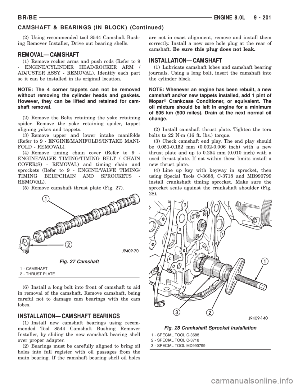
(5) Remove camshaft thrust plate (Fig. 27).
(6) Install a long bolt into front of camshaft to aid
in removal of the camshaft. Remove camshaft, being
careful not to damage cam bearings with the cam
lobes.
INSTALLATIONÐCAMSHAFT BEARINGS
(1) Install new camshaft bearings using recom-
mended Tool 8544 Camshaft Bushing Remover
Installer, by sliding the new camshaft bearing shell
over proper adapter.
(2) Bearings must be carefully aligned to bring oil
holes into full register with oil passages from the
main bearing. If the camshaft bearing shell oil holesare not in exact alignment, remove and install them
correctly. Install a new core hole plug at the rear of
camshaft.Be sure this plug does not leak.
INSTALLATIONÐCAMSHAFT
(1) Lubricate camshaft lobes and camshaft bearing
journals. Using a long bolt, insert the camshaft into
the cylinder block.
NOTE: Whenever an engine has been rebuilt, a new
camshaft and/or new tappets installed, add 1 pint of
MoparTCrankcase Conditioner, or equivalent. The
oil mixture should be left in engine for a minimum
of 805 km (500 miles). Drain at the next normal oil
change.
(2) Install camshaft thrust plate. Tighten the torx
bolts to 22 N´m (16 ft. lbs.) torque.
(3) Check camshaft end play. The end play should
be 0.051-0.152 mm (0.002-0.006 inch) with a new
thrust plate and up to 0.254 mm (0.010 inch) with a
used thrust plate. If not within these limits install a
new thrust plate.
(4) Line up key with keyway in sprocket, then
using Special Tools C-3688, C-3718 and MB990799
install crankshaft timing sprocket. Make sure the
sprocket seats against the crankshaft shoulder (Fig.
28).
Fig. 27 Camshaft
1 - CAMSHAFT
2 - THRUST PLATE
Fig. 28 Crankshaft Sprocket Installation
1 - SPECIAL TOOL C-3688
2 - SPECIAL TOOL C-3718
3 - SPECIAL TOOL MD990799
BR/BEENGINE 8.0L 9 - 201
CAMSHAFT & BEARINGS (IN BLOCK) (Continued)
Page 1383 of 2889
EXCESSIVE WHITE SMOKE
POSSIBLE CAUSE CORRECTION
Fuel injector protrusion not correct. Check washer (shim) at bottom of fuel injector for
correct thickness. (Refer to 14 - FUEL SYSTEM/FUEL
INJECTION/FUEL INJECTOR - INSTALLATION)
Fuel injection pump malfunctioning. A DTC should have been set. Refer to Powertrain
Diagnostic Procedures Information.
Fuel supply side restriction to transfer pump. Refer to Fuel Transfer Pump Pressure (Refer to 14 -
FUEL SYSTEM/FUEL DELIVERY/FUEL TRANSFER
PUMP - DIAGNOSIS AND TESTING)
Fuel transfer (lift) pump malfunctioning. A DTC should have been set. Refer to Powertrain
Diagnostic Procedures Information. Also refer to Fuel
Transfer Pump Pressure Testing (Refer to 14 - FUEL
SYSTEM/FUEL DELIVERY/FUEL TRANSFER PUMP -
DIAGNOSIS AND TESTING).
Intake/Exhaust valve adjustments not correct (too tight). (Refer to 9 - ENGINE/CYLINDER HEAD/INTAKE/
EXHAUST VALVES & SEATS - STANDARD
PROCEDURE).
Intake manifold air temperature sensor malfunctioning. A DTC should have been set. Refer to Powertrain
Diagnostic Procedures Information.
Intake manifold heater circuit not functioning correctly in
cold weather.A DTC should have been set. Refer to Powertrain
Diagnostic Procedures Information. Also check heater
elements for correct operation.
Intake manifold heater elements not functioning
correctly in cold weather.A diagnostic trouble code WILL NOT BE SET if heater
elements are malfunctioning. Refer to NTC tests in
Powertrain Diagnostic Procedures Information.
Internal engine damage (scuffed cylinder). Analyze engine oil and inspect oil filter to locate area of
probable damage.
Restriction in fuel supply side of fuel system. Refer to Fuel Transfer Pump Pressure Testing (Refer to
14 - FUEL SYSTEM/FUEL DELIVERY/FUEL
TRANSFER PUMP - DIAGNOSIS AND TESTING).
Static timing incorrect. A DTC should have been set. If so, (Refer to 14 -
FUEL SYSTEM/FUEL DELIVERY/FUEL INJECTION
PUMP - DIAGNOSIS AND TESTING).
EXCESSIVE BLUE SMOKE
POSSIBLE CAUSE CORRECTION
Dirty air cleaner or restricted turbocharger intake duct. Check Filter MinderTat air filter housing. (Refer to 9 -
ENGINE/AIR INTAKE SYSTEM/AIR CLEANER
ELEMENT - REMOVAL).
Air leak in boost system between turbocharger
compressor outlet and intake manifold.Service air charge system..
Obstruction in exhaust manifold. Remove exhaust manifold and inspect for blockage
(Refer to 9 - ENGINE/MANIFOLDS/EXHAUST
MANIFOLD - REMOVAL).
Restricted turbocharger drain tube. Remove turbocharger drain tube and remove
obstruction.
Crankcase ventilation system plugged. Inspect crankcase breather and vent tube for sludge
formation or obstructions.
9 - 236 ENGINE 5.9L DIESELBR/BE
ENGINE 5.9L DIESEL (Continued)
Page 2696 of 2889
(4) Install the screws attaching the console to
mounting brackets.
(5) Install the transmission shifter boot, (Refer to
23 - BODY/INTERIOR/SHIFT BOOT - INSTALLA-
TION).
(6) Install the transfer case shifter boot, if
equipped. (Refer to 23 - BODY/INTERIOR/SHIFT
BOOT - INSTALLATION).
(7) Install cup holder in console, if equipped.
CARPETS AND FLOOR MATS
REMOVAL
STANDARD CAB
(1) Remove seat (Refer to 23 - BODY/SEATS/SEAT
- BENCH SEAT - REMOVAL) or(Refer to 23 - BODY/
SEATS/SEAT - SPLIT BENCH - REMOVAL).
(2) Remove door sill covers (Refer to 23 - BODY/
INTERIOR/DOOR SILL TRIM - REMOVAL).
(3) Remove cowl trim covers (Refer to 23 - BODY/
INTERIOR/COWL TRIM COVER - REMOVAL).
(4) Remove center console, if equipped.(Refer to 23
- BODY/INTERIOR/CENTER CONSOLE -
REMOVAL)
(5) If not equipped with a center console remove
the transfer case shifter boot (Refer to 23 - BODY/IN-
TERIOR/SHIFT BOOT/TRANSFER CASE - REMOV-
AL).
(6) Remove rear stowage tray (Refer to 23 - BODY/
INTERIOR/REAR FLOOR STOWAGE TRAY -
REMOVAL).
(7) Remove rear closure panel trim (Refer to 23 -
BODY/INTERIOR/REAR CLOSURE PANEL TRIM -
REMOVAL).
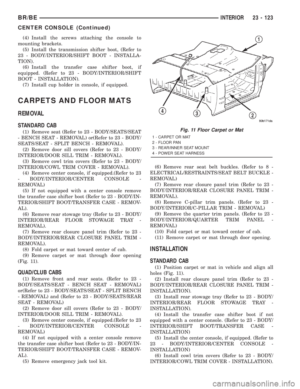
(8) Fold carpet or mat toward center of cab.
(9) Remove carpet or mat through door opening
(Fig. 11).
QUAD/CLUB CABS
(1) Remove front and rear seats. (Refer to 23 -
BODY/SEATS/SEAT - BENCH SEAT - REMOVAL)
or(Refer to 23 - BODY/SEATS/SEAT - SPLIT BENCH
- REMOVAL) and (Refer to 23 - BODY/SEATS/REAR
SEAT - REMOVAL)
(2) Remove door sill covers (Refer to 23 - BODY/
INTERIOR/DOOR SILL TRIM - REMOVAL).
(3) Remove center console, if equipped.(Refer to 23
- BODY/INTERIOR/CENTER CONSOLE -
REMOVAL)
(4) If not equipped with a center console remove
the transfer case shifter boot (Refer to 23 - BODY/IN-
TERIOR/SHIFT BOOT/TRANSFER CASE - REMOV-
AL).
(5) Remove emergency jack tool kit.(6) Remove rear seat belt buckles. (Refer to 8 -
ELECTRICAL/RESTRAINTS/SEAT BELT BUCKLE -
REMOVAL)
(7) Remove rear closure panel trim (Refer to 23 -
BODY/INTERIOR/REAR CLOSURE PANEL TRIM -
REMOVAL).
(8) Remove C-pillar trim panels. (Refer to 23 -
BODY/INTERIOR/C-PILLAR TRIM - REMOVAL)
(9) Remove the quarter trim panels. (Refer to 23 -
BODY/INTERIOR/QUARTER TRIM PANEL -
REMOVAL)
(10) Fold carpet or mat toward center of cab.
(11) Remove carpet or mat through door opening.
INSTALLATION
STANDARD CAB
(1) Position carpet or mat in vehicle and align all
holes (Fig. 11).
(2) Install rear closure panel trim (Refer to 23 -
BODY/INTERIOR/REAR CLOSURE PANEL TRIM -
INSTALLATION).
(3) Install rear stowage tray (Refer to 23 - BODY/
INTERIOR/REAR FLOOR STOWAGE TRAY -
INSTALLATION).
(4) Install the transfer case shifter boot if not
equipped with a center console. (Refer to 23 - BODY/
INTERIOR/SHIFT BOOT/TRANSFER CASE -
INSTALLATION)
(5) Install the center console, if equipped. (Refer to
23 - BODY/INTERIOR/CENTER CONSOLE -
INSTALLATION)
(6) Install cowl trim covers (Refer to 23 - BODY/
INTERIOR/COWL TRIM COVER - INSTALLATION).
Fig. 11 Floor Carpet or Mat
1 - CARPET OR MAT
2 - FLOOR PAN
3 - REAR/INNER SEAT MOUNT
4 - POWER SEAT HARNESS
BR/BEINTERIOR 23 - 123
CENTER CONSOLE (Continued)
Page 2838 of 2889
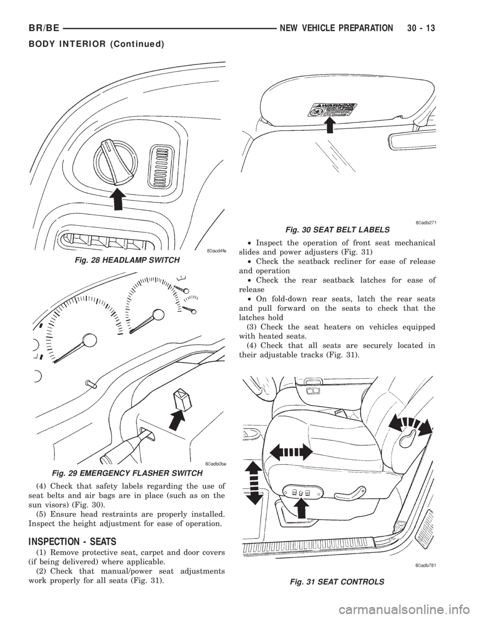
(4) Check that safety labels regarding the use of
seat belts and air bags are in place (such as on the
sun visors) (Fig. 30).
(5) Ensure head restraints are properly installed.
Inspect the height adjustment for ease of operation.
INSPECTION - SEATS
(1) Remove protective seat, carpet and door covers
(if being delivered) where applicable.
(2) Check that manual/power seat adjustments
work properly for all seats (Fig. 31).²Inspect the operation of front seat mechanical
slides and power adjusters (Fig. 31)
²Check the seatback recliner for ease of release
and operation
²Check the rear seatback latches for ease of
release
²On fold-down rear seats, latch the rear seats
and pull forward on the seats to check that the
latches hold
(3) Check the seat heaters on vehicles equipped
with heated seats.
(4) Check that all seats are securely located in
their adjustable tracks (Fig. 31).
Fig. 31 SEAT CONTROLS
Fig. 28 HEADLAMP SWITCH
Fig. 29 EMERGENCY FLASHER SWITCH
Fig. 30 SEAT BELT LABELS
BR/BENEW VEHICLE PREPARATION 30 - 13
BODY INTERIOR (Continued)