wheel alignment DODGE RAM 2001 Service Repair Manual
[x] Cancel search | Manufacturer: DODGE, Model Year: 2001, Model line: RAM, Model: DODGE RAM 2001Pages: 2889, PDF Size: 68.07 MB
Page 44 of 2889
SUSPENSION
TABLE OF CONTENTS
page page
WHEEL ALIGNMENT.......................1
FRONT - 2WD............................7FRONT - 4WD...........................14
REAR..................................26
WHEEL ALIGNMENT
TABLE OF CONTENTS
page page
WHEEL ALIGNMENT
DESCRIPTION............................1
OPERATION.............................2
DIAGNOSIS AND TESTING..................2
PRE-ALIGNMENT........................2
STANDARD PROCEDURE...................2ALIGNMENT INDEPENDENT FRONT
SUSPENSION...........................2
CASTER CORRECTION MEASUREMENT.....3
ALIGNMENT LINK/COIL SUSPENSION........5
SPECIFICATIONS.........................6
WHEEL ALIGNMENT
DESCRIPTION
Wheel alignment is the positioning of the wheels in
relation to the vehicle. This is accomplished through
suspension and steering linkage adjustments. An
alignment is essential for efficient steering, good
directional stability and to minimize tire wear. The
most important measurements of an alignment are
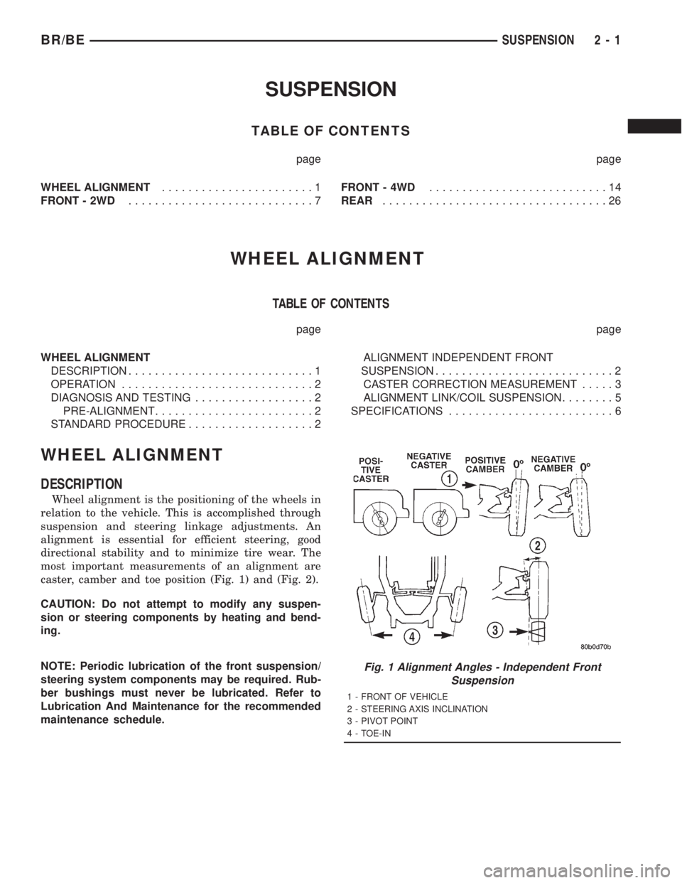
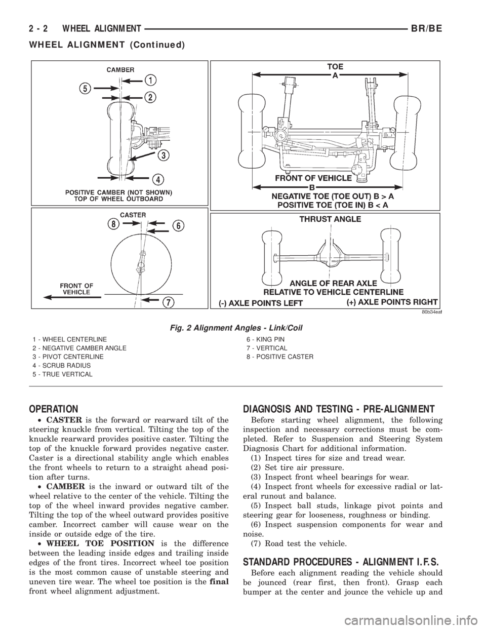
caster, camber and toe position (Fig. 1) and (Fig. 2).
CAUTION: Do not attempt to modify any suspen-
sion or steering components by heating and bend-
ing.
NOTE: Periodic lubrication of the front suspension/
steering system components may be required. Rub-
ber bushings must never be lubricated. Refer to
Lubrication And Maintenance for the recommended
maintenance schedule.
Fig. 1 Alignment Angles - Independent Front
Suspension
1 - FRONT OF VEHICLE
2 - STEERING AXIS INCLINATION
3 - PIVOT POINT
4 - TOE-IN
BR/BESUSPENSION 2 - 1
Page 45 of 2889
OPERATION
²CASTERis the forward or rearward tilt of the
steering knuckle from vertical. Tilting the top of the
knuckle rearward provides positive caster. Tilting the
top of the knuckle forward provides negative caster.
Caster is a directional stability angle which enables
the front wheels to return to a straight ahead posi-
tion after turns.
²CAMBERis the inward or outward tilt of the
wheel relative to the center of the vehicle. Tilting the
top of the wheel inward provides negative camber.
Tilting the top of the wheel outward provides positive
camber. Incorrect camber will cause wear on the
inside or outside edge of the tire.
²WHEEL TOE POSITIONis the difference
between the leading inside edges and trailing inside
edges of the front tires. Incorrect wheel toe position
is the most common cause of unstable steering and
uneven tire wear. The wheel toe position is thefinal
front wheel alignment adjustment.
DIAGNOSIS AND TESTING - PRE-ALIGNMENT
Before starting wheel alignment, the following
inspection and necessary corrections must be com-
pleted. Refer to Suspension and Steering System
Diagnosis Chart for additional information.
(1) Inspect tires for size and tread wear.
(2) Set tire air pressure.
(3) Inspect front wheel bearings for wear.
(4) Inspect front wheels for excessive radial or lat-
eral runout and balance.
(5) Inspect ball studs, linkage pivot points and
steering gear for looseness, roughness or binding.
(6) Inspect suspension components for wear and
noise.
(7) Road test the vehicle.
STANDARD PROCEDURES - ALIGNMENT I.F.S.
Before each alignment reading the vehicle should
be jounced (rear first, then front). Grasp each
bumper at the center and jounce the vehicle up and
Fig. 2 Alignment Angles - Link/Coil
1 - WHEEL CENTERLINE
2 - NEGATIVE CAMBER ANGLE
3 - PIVOT CENTERLINE
4 - SCRUB RADIUS
5 - TRUE VERTICAL6 - KING PIN
7 - VERTICAL
8 - POSITIVE CASTER
2 - 2 WHEEL ALIGNMENTBR/BE
WHEEL ALIGNMENT (Continued)
Page 46 of 2889
down several times. Always release the bumper in
the down position.Set the front end alignment to
specifications while the vehicle is in its NOR-
MALLY LOADED CONDITION.
Camber and caster angle adjustments involve
changing the position of the upper suspension arm
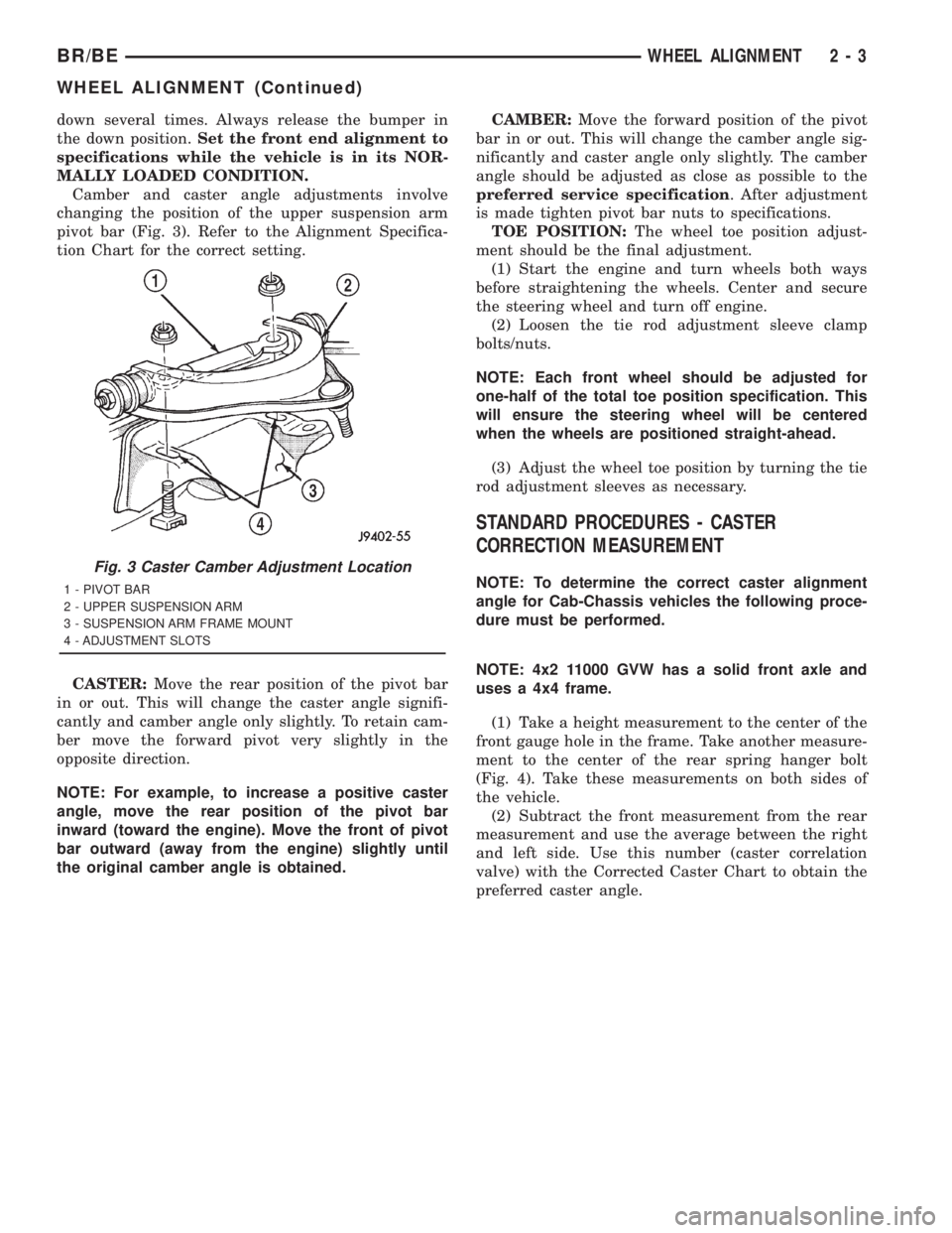
pivot bar (Fig. 3). Refer to the Alignment Specifica-
tion Chart for the correct setting.
CASTER:Move the rear position of the pivot bar
in or out. This will change the caster angle signifi-
cantly and camber angle only slightly. To retain cam-
ber move the forward pivot very slightly in the
opposite direction.
NOTE: For example, to increase a positive caster
angle, move the rear position of the pivot bar
inward (toward the engine). Move the front of pivot
bar outward (away from the engine) slightly until
the original camber angle is obtained.CAMBER:Move the forward position of the pivot
bar in or out. This will change the camber angle sig-
nificantly and caster angle only slightly. The camber
angle should be adjusted as close as possible to the
preferred service specification. After adjustment
is made tighten pivot bar nuts to specifications.
TOE POSITION:The wheel toe position adjust-
ment should be the final adjustment.
(1) Start the engine and turn wheels both ways
before straightening the wheels. Center and secure
the steering wheel and turn off engine.
(2) Loosen the tie rod adjustment sleeve clamp
bolts/nuts.
NOTE: Each front wheel should be adjusted for
one-half of the total toe position specification. This
will ensure the steering wheel will be centered
when the wheels are positioned straight-ahead.
(3) Adjust the wheel toe position by turning the tie
rod adjustment sleeves as necessary.
STANDARD PROCEDURES - CASTER
CORRECTION MEASUREMENT
NOTE: To determine the correct caster alignment
angle for Cab-Chassis vehicles the following proce-
dure must be performed.
NOTE: 4x2 11000 GVW has a solid front axle and
uses a 4x4 frame.
(1) Take a height measurement to the center of the
front gauge hole in the frame. Take another measure-
ment to the center of the rear spring hanger bolt
(Fig. 4). Take these measurements on both sides of
the vehicle.
(2) Subtract the front measurement from the rear
measurement and use the average between the right
and left side. Use this number (caster correlation
valve) with the Corrected Caster Chart to obtain the
preferred caster angle.
Fig. 3 Caster Camber Adjustment Location
1 - PIVOT BAR
2 - UPPER SUSPENSION ARM
3 - SUSPENSION ARM FRAME MOUNT
4 - ADJUSTMENT SLOTS
BR/BEWHEEL ALIGNMENT 2 - 3
WHEEL ALIGNMENT (Continued)
Page 47 of 2889
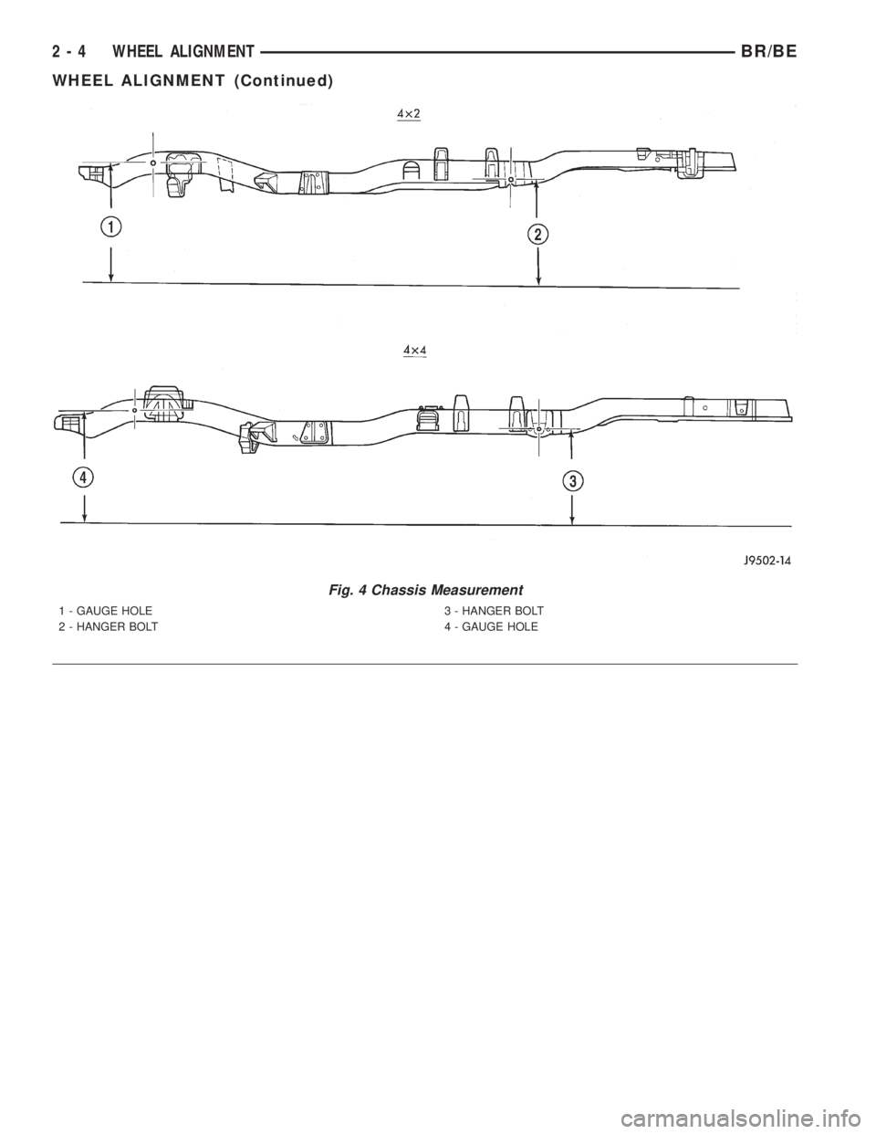
Fig. 4 Chassis Measurement
1 - GAUGE HOLE
2 - HANGER BOLT3 - HANGER BOLT
4 - GAUGE HOLE
2 - 4 WHEEL ALIGNMENTBR/BE
WHEEL ALIGNMENT (Continued)
Page 48 of 2889
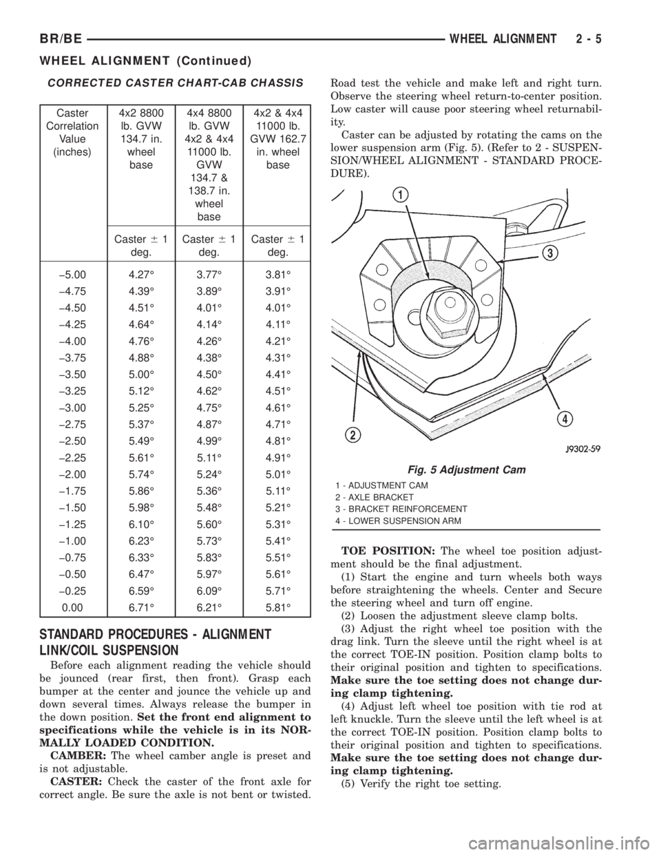
CORRECTED CASTER CHART-CAB CHASSIS
Caster
Correlation
Value
(inches)4x2 8800
lb. GVW
134.7 in.
wheel
base4x4 8800
lb. GVW
4x2 & 4x4
11000 lb.
GVW
134.7 &
138.7 in.
wheel
base4x2 & 4x4
11000 lb.
GVW 162.7
in. wheel
base
Caster61
deg.Caster61
deg.Caster61
deg.
þ5.00 4.27É 3.77É 3.81É
þ4.75 4.39É 3.89É 3.91É
þ4.50 4.51É 4.01É 4.01É
þ4.25 4.64É 4.14É 4.11É
þ4.00 4.76É 4.26É 4.21É
þ3.75 4.88É 4.38É 4.31É
þ3.50 5.00É 4.50É 4.41É
þ3.25 5.12É 4.62É 4.51É
þ3.00 5.25É 4.75É 4.61É
þ2.75 5.37É 4.87É 4.71É
þ2.50 5.49É 4.99É 4.81É
þ2.25 5.61É 5.11É 4.91É
þ2.00 5.74É 5.24É 5.01É
þ1.75 5.86É 5.36É 5.11É
þ1.50 5.98É 5.48É 5.21É
þ1.25 6.10É 5.60É 5.31É
þ1.00 6.23É 5.73É 5.41É
þ0.75 6.33É 5.83É 5.51É
þ0.50 6.47É 5.97É 5.61É
þ0.25 6.59É 6.09É 5.71É
0.00 6.71É 6.21É 5.81É
STANDARD PROCEDURES - ALIGNMENT
LINK/COIL SUSPENSION
Before each alignment reading the vehicle should
be jounced (rear first, then front). Grasp each
bumper at the center and jounce the vehicle up and
down several times. Always release the bumper in
the down position.Set the front end alignment to
specifications while the vehicle is in its NOR-
MALLY LOADED CONDITION.
CAMBER:The wheel camber angle is preset and
is not adjustable.
CASTER:Check the caster of the front axle for
correct angle. Be sure the axle is not bent or twisted.Road test the vehicle and make left and right turn.
Observe the steering wheel return-to-center position.
Low caster will cause poor steering wheel returnabil-
ity.
Caster can be adjusted by rotating the cams on the
lower suspension arm (Fig. 5). (Refer to 2 - SUSPEN-
SION/WHEEL ALIGNMENT - STANDARD PROCE-
DURE).
TOE POSITION:The wheel toe position adjust-
ment should be the final adjustment.
(1) Start the engine and turn wheels both ways
before straightening the wheels. Center and Secure
the steering wheel and turn off engine.
(2) Loosen the adjustment sleeve clamp bolts.
(3) Adjust the right wheel toe position with the
drag link. Turn the sleeve until the right wheel is at
the correct TOE-IN position. Position clamp bolts to
their original position and tighten to specifications.
Make sure the toe setting does not change dur-
ing clamp tightening.
(4) Adjust left wheel toe position with tie rod at
left knuckle. Turn the sleeve until the left wheel is at
the correct TOE-IN position. Position clamp bolts to
their original position and tighten to specifications.
Make sure the toe setting does not change dur-
ing clamp tightening.
(5) Verify the right toe setting.
Fig. 5 Adjustment Cam
1 - ADJUSTMENT CAM
2 - AXLE BRACKET
3 - BRACKET REINFORCEMENT
4 - LOWER SUSPENSION ARM
BR/BEWHEEL ALIGNMENT 2 - 5
WHEEL ALIGNMENT (Continued)
Page 49 of 2889
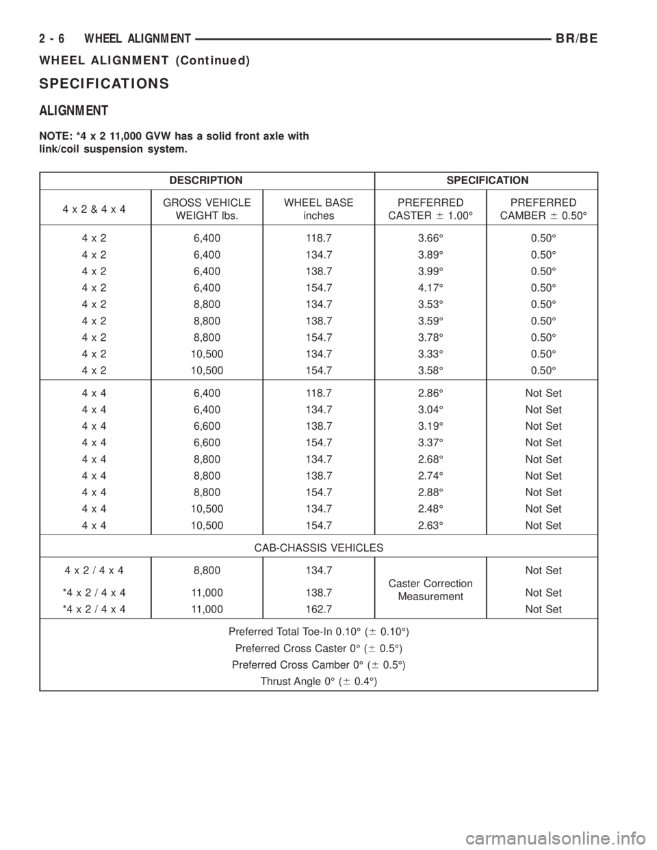
SPECIFICATIONS
ALIGNMENT
NOTE: *4x211,000 GVW has a solid front axle with
link/coil suspension system.
DESCRIPTION SPECIFICATION
4x2&4x4GROSS VEHICLE
WEIGHT lbs.WHEEL BASE
inchesPREFERRED
CASTER61.00ÉPREFERRED
CAMBER60.50É
4 x 2 6,400 118.7 3.66É 0.50É
4 x 2 6,400 134.7 3.89É 0.50É
4 x 2 6,400 138.7 3.99É 0.50É
4 x 2 6,400 154.7 4.17É 0.50É
4 x 2 8,800 134.7 3.53É 0.50É
4 x 2 8,800 138.7 3.59É 0.50É
4 x 2 8,800 154.7 3.78É 0.50É
4 x 2 10,500 134.7 3.33É 0.50É
4 x 2 10,500 154.7 3.58É 0.50É
4 x 4 6,400 118.7 2.86É Not Set
4 x 4 6,400 134.7 3.04É Not Set
4 x 4 6,600 138.7 3.19É Not Set
4 x 4 6,600 154.7 3.37É Not Set
4 x 4 8,800 134.7 2.68É Not Set
4 x 4 8,800 138.7 2.74É Not Set
4 x 4 8,800 154.7 2.88É Not Set
4 x 4 10,500 134.7 2.48É Not Set
4 x 4 10,500 154.7 2.63É Not Set
CAB-CHASSIS VEHICLES
4x2/4x48,800 134.7
Caster Correction
MeasurementNot Set
*4x2/4x4 11,000 138.7 Not Set
*4x2/4x4 11,000 162.7 Not Set
Preferred Total Toe-In 0.10É (60.10É)
Preferred Cross Caster 0É (60.5É)
Preferred Cross Camber 0É (60.5É)
Thrust Angle 0É (60.4É)
2 - 6 WHEEL ALIGNMENTBR/BE
WHEEL ALIGNMENT (Continued)
Page 56 of 2889
(3) Position the indicator plunger against the
upper ball stud boss of the steering knuckle.
(4) Grasp the top of the tire and apply force in and
out. Look for movement at the ball joint between the
upper suspension arm and steering knuckle.
(5) If lateral movement is greater than 0.8 mm
(0.030 in.), replace the suspension arm.
UPPER CONTROL ARM
REMOVAL
(1) Raise and support vehicle.
(2) Remove tire and wheel assembly.
(3) Support lower suspension arm at outboard end
with jack stand.(4) Remove upper ball joint cotter pin and nut.
(5) Separate ball joint from knuckle with remover
MB-990635.
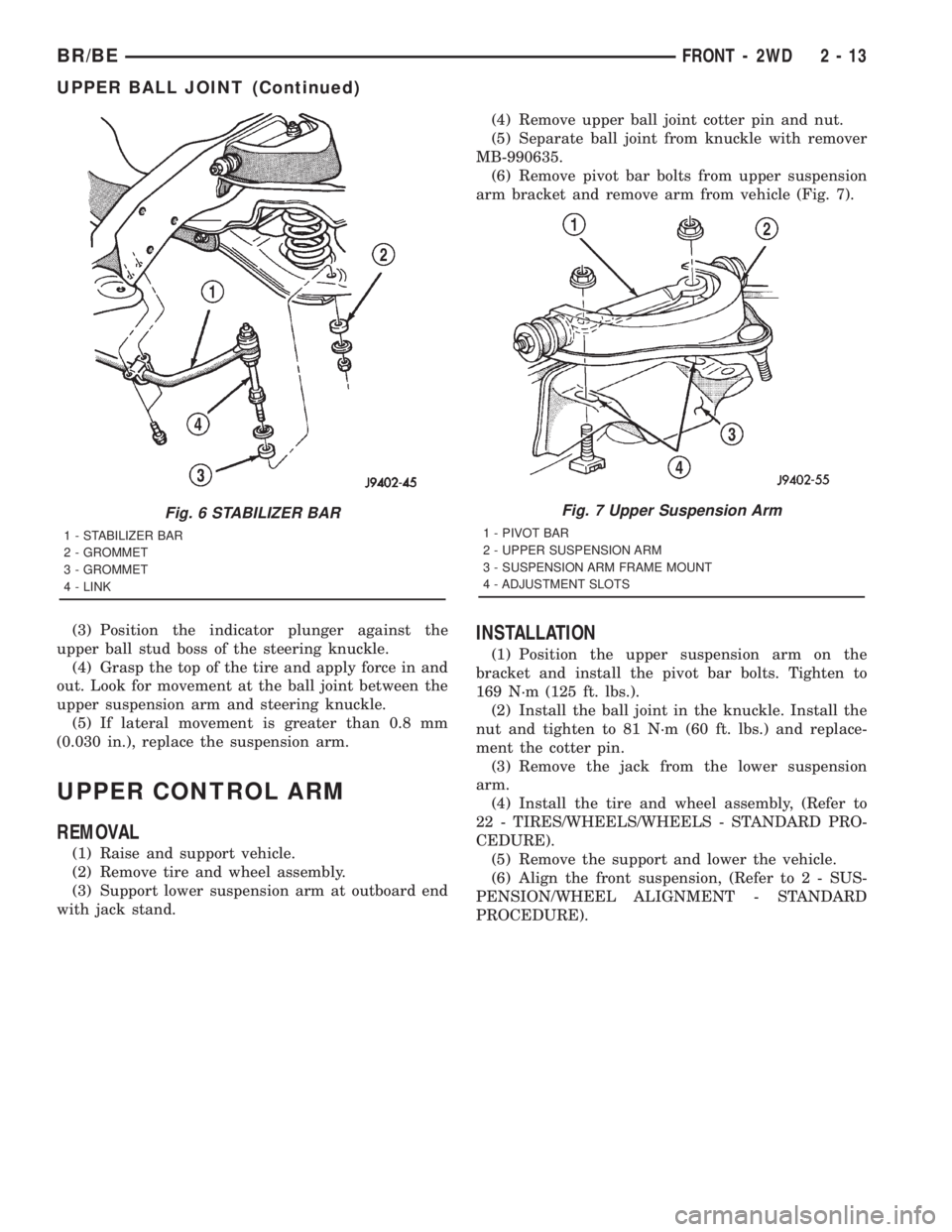
(6) Remove pivot bar bolts from upper suspension
arm bracket and remove arm from vehicle (Fig. 7).
INSTALLATION
(1) Position the upper suspension arm on the
bracket and install the pivot bar bolts. Tighten to
169 N´m (125 ft. lbs.).
(2) Install the ball joint in the knuckle. Install the
nut and tighten to 81 N´m (60 ft. lbs.) and replace-
ment the cotter pin.
(3) Remove the jack from the lower suspension
arm.
(4) Install the tire and wheel assembly, (Refer to
22 - TIRES/WHEELS/WHEELS - STANDARD PRO-
CEDURE).
(5) Remove the support and lower the vehicle.
(6) Align the front suspension, (Refer to 2 - SUS-
PENSION/WHEEL ALIGNMENT - STANDARD
PROCEDURE).
Fig. 6 STABILIZER BAR
1 - STABILIZER BAR
2 - GROMMET
3 - GROMMET
4 - LINK
Fig. 7 Upper Suspension Arm
1 - PIVOT BAR
2 - UPPER SUSPENSION ARM
3 - SUSPENSION ARM FRAME MOUNT
4 - ADJUSTMENT SLOTS
BR/BEFRONT - 2WD 2 - 13
UPPER BALL JOINT (Continued)
Page 63 of 2889
(8) Install a new cotter pin in hub nut. Tighten the
nut as needed to align cotter pin hole in shaft with
the opening in the nut.
(9) Install the rotor, brake caliper with adapter,
(Refer to 5 - BRAKES/HYDRAULIC/MECHANICAL/
DISC BRAKE CALIPERS - INSTALLATION).
(10) Install the ABS wheel speed sensor if
equipped, (Refer to 5 - BRAKES/ELECTRICAL/
FRONT WHEEL SPEED SENSOR - INSTALLA-
TION).
(11) Install the wheel and tire assemblies, (Refer
to 22 - TIRES/WHEELS/WHEELS - STANDARD
PROCEDURE).
(12) Remove the support and lower the vehicle.
(13) Apply the brakes several times to seat the
brake shoes and the caliper piston. Do not move the
vehicle until a firm brake pedal is obtained.
KNUCKLE
DESCRIPTION
The knuckles are a single casting with legs
machined for the upper and lower ball joints. The
knuckles also has machined mounting locations for
the front brake calipers adapters and hub bearing
assembly.
OPERATION
The steering knuckles pivots between the upper
and lower ball joints. The steering linkage is
attached to the knuckles controls vehicle steering.
REMOVAL
(1) Remove hub bearing and axle shaft.
(2) Remove tie-rod or drag link end from the steer-
ing knuckle arm.
(3) Remove the ABS sensor wire and bracket from
knuckle.
(4) Remove the cotter pin from the upper ball stud
nut. Remove the upper and lower ball stud nuts.
(5) Strike the steering knuckle with a brass ham-
mer to loosen. Remove knuckle from axle tube yokes.
REMOVAL
(1) Remove hub bearing and axle shaft.
(2) Remove tie-rod or drag link end from the steer-
ing knuckle arm.
(3) Remove the ABS sensor wire and bracket from
knuckle. Refer to Brakes, for proper procedures.
(4) Remove the cotter pin from the upper ball stud
nut. Remove the upper and lower ball stud nuts.
(5) Strike the steering knuckle with a brass ham-
mer to loosen.
(6) Remove knuckle from axle tube yokes.
INSTALLATION
(1) Position the steering knuckle on the ball studs.
(2) Install and tighten lower ball stud nut to 108
N´m (80 ft. lbs.) torque. Advance nut to next slot to
line up hole and install new cotter pin.
(3) Install and tighten upper ball stud nut to 101
N´m (75 ft. lbs.) torque. Advance nut to next slot to
line up hole and install new cotter pin.
(4) Install the hub bearing and axle shaft.
(5) Install tie-rod or drag link end onto the steer-
ing knuckle arm.
(6) Install the ABS sensor wire and bracket to the
knuckle. Refer to Brakes, for proper procedures.
INSTALLATION
(1) Position the steering knuckle on the ball studs.
(2) Install and tighten lower ball stud nut to 47
N´m (35 ft. lbs.) torque. Do not install cotter pin at
this time.
(3) Install and tighten upper ball stud nut to 94
N´m (70 ft. lbs.) torque. Advance nut to next slot to
line up hole and install new cotter pin.
(4) Retorque lower ball stud nut to 190±217 N´m
(140±160 ft. lbs.) torque. Advance nut to next slot to
line up hole and install new cotter pin.
(5) Install the hub bearing and axle shaft.
(6) Install tie-rod or drag link end onto the steer-
ing knuckle arm.
(7) Install the ABS sensor wire and bracket to the
knuckle. Refer to Brakes, for proper procedure.
LOWER CONTROL ARM
REMOVAL
(1) Raise and support the vehicle.
(2) Paint or scribe alignment marks on the cam
adjusters and suspension arm for installation refer-
ence (Fig. 15).
(3) Remove the lower suspension arm nut, cam
and cam bolt from the axle.
(4) Remove the nut and bolt from the frame rail
bracket and remove the lower suspension arm (Fig.
22).
INSTALLATION
(1) Position the lower suspension arm at the axle
bracket and frame rail bracket.
(2) Install the rear bolt and finger tighten the nut.
(3) Install the cam bolt, cam and nut in the axle
and align the reference marks.
(4) Remove support and lower the vehicle.
(5) Tighten cam nut at the axle bracket to 190
N´m (140 ft. lbs.). Tighten rear nut at the frame
bracket to 190 N´m (140 ft. lbs.).
2 - 20 FRONT - 4WDBR/BE
HUB / BEARING (Continued)
Page 78 of 2889
(15) If the vibration remains unacceptable, apply
the same steps to the front end of the propeller shaft.
(16) Install the wheel and tires. Lower the vehicle.
RUNOUT
(1) Remove dirt, rust, paint and undercoating from
the propeller shaft surface where the dial indicator
will contact the shaft.
(2) The dial indicator must be installed perpendic-
ular to the shaft surface.
(3) Measure runout at the center and ends of the
shaft sufficiently far away from weld areas to ensure
that the effects of the weld process will not enter into
the measurements.
(4) Refer to Runout Specifications chart.
(5) If the propeller shaft runout is out of specifica-
tion, remove the propeller shaft, index the shaft 180É,
and re-install the propeller shaft. Measure shaft
runout again.
(6) If the propeller shaft runout is now within
specifications, mark the shaft and yokes for proper
orientation.
(7) If the propeller shaft runout is not within spec-
ifications, verify that the runout of the transmission/
transfer case and axle are within specifications.
Correct as necessary and re-measure propeller shaft
runout.
(8) Replace the propeller shaft if the runout still
exceeds the limits.
RUNOUT SPECIFICATIONS
Front of Shaft 0.020 in. (0.50 mm)
Center of Shaft 0.025 in. (0.63 mm)
Rear of Shaft 0.020 in. (0.50 mm)
note:
Measure front/rear runout approximately 3 inches
(76 mm) from the weld seam at each end of the
shaft tube for tube lengths over 30 inches. For
tube lengths under 30 inches, the maximum
allowed runout is 0.020 in. (0.50 mm) for the full
length of the tube.
STANDARD PROCEDURES
To accurately check driveline alignment, raise and
support the vehicle at the axles as level as possible.
Allow the wheels and propeller shaft to turn.
(1) Remove any external bearing snap rings, if
equipped, from universal joint so protractor base sits
flat.
(2) Rotate the shaft until transmission/transfer
case output yoke bearing is facing downward.
NOTE: Always make measurements from front to
rear and from the same side of the vehicle.
Fig. 6 Clamp Screw At Position 1
1 - CLAMP
2 - SCREWDRIVER
Fig. 7 Two Clamp Screws At The Same Position
Fig. 8 Clamp Screws Separated
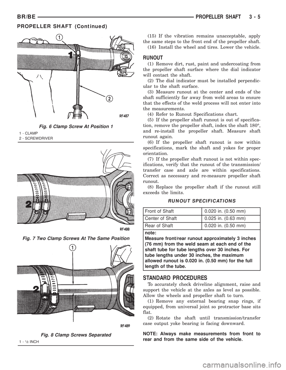
1-1¤2INCH
BR/BEPROPELLER SHAFT 3 - 5
PROPELLER SHAFT (Continued)
Page 88 of 2889
DIAGNOSTIC CHART
Condition Possible Causes Correction
Wheel Noise 1. Wheel loose. 1. Tighten loose nuts.
2. Faulty, brinelled wheel bearing. 2. Replace bearing.
Axle Shaft Noise 1. Misaligned axle tube. 1. Inspect axle tube alignment. Correct
as necessary.
2. Bent or sprung axle shaft. 2. Inspect and correct as necessary.
3. End-play in pinion bearings. 3. Refer to pinion pre-load information
and correct as necessary.
4. Excessive gear backlash between the
ring gear and pinion.4. Check adjustment of the ring gear
and pinion backlash. Correct as
necessary.
5. Improper adjustment of pinion gear
bearings.5. Adjust the pinion bearings pre-load.
6. Loose pinion yoke nut. 6. Tighten the pinion yoke nut.
7. Scuffed gear tooth contact surfaces. 7. Inspect and replace as necessary.
Axle Shaft Broke 1. Misaligned axle tube. 1. Replace the broken shaft after
correcting tube mis-alignment.
2 Vehicle overloaded. 2. Replace broken shaft and avoid
excessive weight on vehicle.
3. Erratic clutch operation. 3. Replace broken shaft and avoid or
correct erratic clutch operation.
4. Grabbing clutch. 4. Replace broken shaft and inspect and
repair clutch as necessary.
Differential Cracked 1. Improper adjustment of the
differential bearings.1. Replace case and inspect gears and
bearings for further damage. Set
differential bearing pre-load properly.
2. Excessive ring gear backlash. 2. Replace case and inspect gears and
bearings for further damage. Set ring
gear backlash properly.
3. Vehicle overloaded. 3. Replace case and inspect gears and
bearings for further damage. Avoid
excessive vehicle weight.
4. Erratic clutch operation. 4. Replace case and inspect gears and
bearings for further damage. Avoid
erratic use of clutch.
Differential Gears Scored 1. Insufficient lubrication. 1. Replace scored gears. Fill differential
with the correct fluid type and quantity.
2. Improper grade of lubricant. 2. Replace scored gears. Fill differential
with the correct fluid type and quantity.
3. Excessive spinning of one wheel/tire. 3. Replace scored gears. Inspect all
gears, pinion bores, and shaft for
damage. Service as necessary.
BR/BEFRONT AXLE - 216FBI 3 - 15
FRONT AXLE - 216FBI (Continued)