maintenance reset DODGE RAM 2001 Service Repair Manual
[x] Cancel search | Manufacturer: DODGE, Model Year: 2001, Model line: RAM, Model: DODGE RAM 2001Pages: 2889, PDF Size: 68.07 MB
Page 587 of 2889

turn on the seatbelt indicator for the following rea-
sons:
²Seatbelt Reminder Function- Each time the
cluster receives a battery current input on the fused
ignition switch output (st-run) circuit, the indicator
will be illuminated as a seatbelt reminder for about
seven seconds, or until the ignition switch is turned
to the Off position, whichever occurs first. This
reminder function will occur regardless of the status
of the seatbelt switch input to the cluster.
²Driver Side Front Seatbelt Not Buckled-
Following the seatbelt reminder function, each time
the cluster receives a ground input on the seat belt
switch sense circuit (seatbelt switch closed - seatbelt
unbuckled) with the ignition switch in the Start or
On positions, the indicator will be illuminated. The
seatbelt indicator remains illuminated until the seat
belt switch sense input to the cluster is an open cir-
cuit (seatbelt switch opened - seatbelt buckled), or
until the ignition switch is turned to the Off position,
whichever occurs first.
²Actuator Test- Each time the cluster is put
through the actuator test, the indicator will be
turned on during the bulb check portion of the test to
confirm the functionality of the LED and the cluster
control circuitry.
The seatbelt switch input to the instrument cluster
circuitry can be diagnosed using conventional diag-
nostic tools and methods. For further diagnosis of the
seatbelt indicator or the instrument cluster circuitry
that controls the LED, (Refer to 8 - ELECTRICAL/
INSTRUMENT CLUSTER - DIAGNOSIS AND
TESTING).
SERVICE REMINDER
INDICATOR
DESCRIPTION
A Service Reminder Indicator (SRI) is standard
equipment on all instrument clusters. However, on
vehicles not equipped with certain optional heavy
duty emission cycle gasoline engines, this indicator is
electronically disabled. The SRI is located near the
lower edge of the instrument cluster overlay, to the
left of center. The SRI consists of a stencilled cutout
of the words ªMAINT REQDº in the opaque layer of
the instrument cluster overlay. The dark outer layer
of the overlay prevents the indicator from being
clearly visible when it is not illuminated. An amber
lens behind the cutout in the opaque layer of the
overlay causes the ªMAINT REQDº text to appear in
amber through the translucent outer layer of the
overlay when the indicator is illuminated from
behind by a Light Emitting Diode (LED) soldered
onto the instrument cluster electronic circuit board.The SRI is serviced as a unit with the instrument
cluster.
OPERATION
The Service Reminder Indicator (SRI) gives an
indication to the vehicle operator when engine emis-
sions maintenance procedures should be performed.
This indicator is controlled by a transistor on the
instrument cluster circuit board based upon the clus-
ter programming and electronic messages received by
the cluster from the Powertrain Control Module
(PCM) over the Chrysler Collision Detection (CCD)
data bus. The SRI Light Emitting Diode (LED)
receives battery current on the instrument cluster
electronic circuit board through the fused ignition
switch output (st-run) circuit whenever the ignition
switch is in the On or Start positions; therefore, the
LED will always be off when the ignition switch is in
any position except On or Start. The LED only illu-
minates when it is provided a path to ground by the
instrument cluster transistor. The instrument cluster
will turn on the SRI for the following reasons:
²Bulb Test- Each time the ignition switch is
turned to the On position the SRI is illuminated for
about two seconds as a bulb test.
²Service Required Lamp-On Message- Each
time the cluster receives a service required lamp-on
message from the PCM indicating that an emissions
maintenance interval has been reached, the SRI will
be illuminated. The indicator remains illuminated
until the cluster receives a service required lamp-off
message from the PCM, or until the ignition switch
is turned to the Off position, whichever occurs first.
²Actuator Test- Each time the cluster is put
through the actuator test, the SRI will be turned on
during the bulb check portion of the test to confirm
the functionality of the LED and the cluster control
circuitry.
The PCM continually monitors the vehicle speed
sensor to determine the distance the vehicle has been
driven, then sends the proper messages to the instru-
ment cluster. Once the SRI has been illuminated and
the required emissions maintenance procedures have
been completed, the PCM must be reset using a
DRBIIItscan tool before it will send the proper ser-
vice required lamp-off message to the instrument
cluster. Refer to the appropriate diagnostic informa-
tion. For further diagnosis of the SRI or the instru-
ment cluster circuitry that controls the LED, (Refer
to 8 - ELECTRICAL/INSTRUMENT CLUSTER -
DIAGNOSIS AND TESTING). For proper diagnosis
of the PCM, the CCD data bus, or the message
inputs to the instrument cluster that control the SRI,
a DRBIIItscan tool is required. Refer to the appro-
priate diagnostic information.
8J - 28 INSTRUMENT CLUSTERBR/BE
SEATBELT INDICATOR (Continued)
Page 2842 of 2889

INSPECTION - PARKING BRAKE
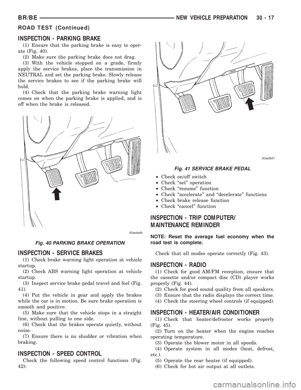
(1) Ensure that the parking brake is easy to oper-
ate (Fig. 40).
(2) Make sure the parking brake does not drag.
(3) With the vehicle stopped on a grade, firmly
apply the service brakes, place the transmission in
NEUTRAL and set the parking brake. Slowly release
the service brakes to see if the parking brake will
hold.
(4) Check that the parking brake warning light
comes on when the parking brake is applied, and is
off when the brake is released.
INSPECTION - SERVICE BRAKES
(1) Check brake warning light operation at vehicle
startup.
(2) Check ABS warning light operation at vehicle
startup.
(3) Inspect service brake pedal travel and feel (Fig.
41).
(4) Put the vehicle in gear and apply the brakes
while the car is in motion. Be sure brake operation is
smooth and positive.
(5) Make sure that the vehicle stops in a straight
line, without pulling to one side.
(6) Check that the brakes operate quietly, without
noise.
(7) Ensure there is no shudder or vibration when
braking.
INSPECTION - SPEED CONTROL
Check the following speed control functions (Fig.
42):²Check on/off switch
²Check ªsetº operation
²Check ªresumeº function
²Check ªaccelerateº and ªdecelerateº functions
²Check brake release function
²Check ªcancelº function
INSPECTION - TRIP COMPUTER/
MAINTENANCE REMINDER
NOTE: Reset the average fuel economy when the
road test is complete.
Check that all modes operate correctly (Fig. 43).
INSPECTION - RADIO
(1) Check for good AM/FM reception, ensure that
the cassette and/or compact disc (CD) player works
properly (Fig. 44).
(2) Check for good sound quality from all speakers.
(3) Ensure that the radio displays the correct time.
(4) Check the steering wheel controls (if equipped).
INSPECTION - HEATER/AIR CONDITIONER
(1) Check that heater/defroster works properly
(Fig. 45).
(2) Turn on the heater when the engine reaches
operating temperature.
(3) Operate the blower motor in all speeds.
(4) Operate system in all modes (heat, defrost,
etc.).
(5) Operate the rear heater (if equipped).
(6) Check for hot air output at all outlets.
Fig. 40 PARKING BRAKE OPERATION
Fig. 41 SERVICE BRAKE PEDAL
BR/BENEW VEHICLE PREPARATION 30 - 17
ROAD TEST (Continued)