map DODGE RAM 2001 Service Repair Manual
[x] Cancel search | Manufacturer: DODGE, Model Year: 2001, Model line: RAM, Model: DODGE RAM 2001Pages: 2889, PDF Size: 68.07 MB
Page 466 of 2889
During Open Loop modes, the PCM receives input
signals and responds only according to preset PCM
programming. Input from the oxygen (O2S) sensors
is not monitored during Open Loop modes.
During Closed Loop modes, the PCM will monitor
the oxygen (O2S) sensors input. This input indicates
to the PCM whether or not the calculated injector
pulse width results in the ideal air-fuel ratio. This
ratio is 14.7 parts air-to-1 part fuel. By monitoring
the exhaust oxygen content through the O2S sensor,
the PCM can fine tune the injector pulse width. This
is done to achieve optimum fuel economy combined
with low emission engine performance.
The fuel injection system has the following modes
of operation:
²Ignition switch ON
²Engine start-up (crank)
²Engine warm-up
²Idle
²Cruise
²Acceleration
²Deceleration
²Wide open throttle (WOT)
²Ignition switch OFF
The ignition switch On, engine start-up (crank),
engine warm-up, acceleration, deceleration and wide
open throttle modes are Open Loop modes. The idle
and cruise modes, (with the engine at operating tem-
perature) are Closed Loop modes.
IGNITION SWITCH (KEY-ON) MODE
This is an Open Loop mode. When the fuel system
is activated by the ignition switch, the following
actions occur:²The PCM pre-positions the idle air control (IAC)
motor.
²The PCM determines atmospheric air pressure
from the MAP sensor input to determine basic fuel
strategy.
²The PCM monitors the engine coolant tempera-
ture sensor input. The PCM modifies fuel strategy
based on this input.
²Intake manifold air temperature sensor input is
monitored.
²Throttle position sensor (TPS) is monitored.
²The auto shutdown (ASD) relay is energized by
the PCM for approximately three seconds.
²The fuel pump is energized through the fuel
pump relay by the PCM. The fuel pump will operate
for approximately three seconds unless the engine is
operating or the starter motor is engaged.
²The O2S sensor heater element is energized via
the ASD relay. The O2S sensor input is not used by
the PCM to calibrate air-fuel ratio during this mode
of operation.
ENGINE START-UP MODE
This is an Open Loop mode. The following actions
occur when the starter motor is engaged.
The PCM receives inputs from:
²Battery voltage
²Engine coolant temperature sensor
²Crankshaft position sensor
²Intake manifold air temperature sensor
²Manifold absolute pressure (MAP) sensor
²Throttle position sensor (TPS)
²Starter motor relay
²Camshaft position sensor signal
The PCM monitors the crankshaft position sensor.
If the PCM does not receive a crankshaft position
sensor signal within 3 seconds of cranking the
engine, it will shut down the fuel injection system.
The fuel pump is activated by the PCM through
the fuel pump relay.
Voltage is applied to the fuel injectors with the
ASD relay via the PCM. The PCM will then control
the injection sequence and injector pulse width by
turning the ground circuit to each individual injector
on and off.
The PCM determines the proper ignition timing
according to input received from the crankshaft posi-
tion sensor.
ENGINE WARM-UP MODE
This is an Open Loop mode. During engine warm-
up, the PCM receives inputs from:
²Battery voltage
²Crankshaft position sensor
²Engine coolant temperature sensor
²Intake manifold air temperature sensor
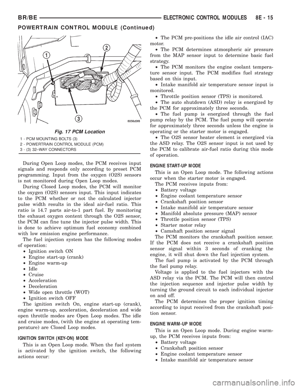
Fig. 17 PCM Location
1 - PCM MOUNTING BOLTS (3)
2 - POWERTRAIN CONTROL MODULE (PCM)
3 - (3) 32±WAY CONNECTORS
BR/BEELECTRONIC CONTROL MODULES 8E - 15
POWERTRAIN CONTROL MODULE (Continued)
Page 467 of 2889
²Manifold absolute pressure (MAP) sensor
²Throttle position sensor (TPS)
²Camshaft position sensor signal (in the distribu-
tor)
²Park/neutral switch (gear indicator signalÐauto.
trans. only)
²Air conditioning select signal (if equipped)
²Air conditioning request signal (if equipped)
Based on these inputs the following occurs:
²Voltage is applied to the fuel injectors with the
ASD relay via the PCM. The PCM will then control
the injection sequence and injector pulse width by
turning the ground circuit to each individual injector
on and off.
²The PCM adjusts engine idle speed through the
idle air control (IAC) motor and adjusts ignition tim-
ing.
²The PCM operates the A/C compressor clutch
through the clutch relay. This is done if A/C has been
selected by the vehicle operator and requested by the
A/C thermostat.
²When engine has reached operating tempera-
ture, the PCM will begin monitoring O2S sensor
input. The system will then leave the warm-up mode
and go into closed loop operation.
IDLE MODE
When the engine is at operating temperature, this
is a Closed Loop mode. At idle speed, the PCM
receives inputs from:
²Air conditioning select signal (if equipped)
²Air conditioning request signal (if equipped)
²Battery voltage
²Crankshaft position sensor
²Engine coolant temperature sensor
²Intake manifold air temperature sensor
²Manifold absolute pressure (MAP) sensor
²Throttle position sensor (TPS)
²Camshaft position sensor signal (in the distribu-
tor)
²Battery voltage
²Park/neutral switch (gear indicator signalÐauto.
trans. only)
²Oxygen sensors
Based on these inputs, the following occurs:
²Voltage is applied to the fuel injectors with the
ASD relay via the PCM. The PCM will then control
injection sequence and injector pulse width by turn-
ing the ground circuit to each individual injector on
and off.
²The PCM monitors the O2S sensor input and
adjusts air-fuel ratio by varying injector pulse width.
It also adjusts engine idle speed through the idle air
control (IAC) motor.
²The PCM adjusts ignition timing by increasing
and decreasing spark advance.²The PCM operates the A/C compressor clutch
through the clutch relay. This happens if A/C has
been selected by the vehicle operator and requested
by the A/C thermostat.
CRUISE MODE
When the engine is at operating temperature, this
is a Closed Loop mode. At cruising speed, the PCM
receives inputs from:
²Air conditioning select signal (if equipped)
²Air conditioning request signal (if equipped)
²Battery voltage
²Engine coolant temperature sensor
²Crankshaft position sensor
²Intake manifold air temperature sensor
²Manifold absolute pressure (MAP) sensor
²Throttle position sensor (TPS)
²Camshaft position sensor signal (in the distribu-
tor)
²Park/neutral switch (gear indicator signalÐauto.
trans. only)
²Oxygen (O2S) sensors
Based on these inputs, the following occurs:
²Voltage is applied to the fuel injectors with the
ASD relay via the PCM. The PCM will then adjust
the injector pulse width by turning the ground circuit
to each individual injector on and off.
²The PCM monitors the O2S sensor input and
adjusts air-fuel ratio. It also adjusts engine idle
speed through the idle air control (IAC) motor.
²The PCM adjusts ignition timing by turning the
ground path to the coil on and off.
²The PCM operates the A/C compressor clutch
through the clutch relay. This happens if A/C has
been selected by the vehicle operator and requested
by the A/C thermostat.
ACCELERATION MODE
This is an Open Loop mode. The PCM recognizes
an abrupt increase in throttle position or MAP pres-
sure as a demand for increased engine output and
vehicle acceleration. The PCM increases injector
pulse width in response to increased throttle opening.
DECELERATION MODE
When the engine is at operating temperature, this
is an Open Loop mode. During hard deceleration, the
PCM receives the following inputs.
²Air conditioning select signal (if equipped)
²Air conditioning request signal (if equipped)
²Battery voltage
²Engine coolant temperature sensor
²Crankshaft position sensor
²Intake manifold air temperature sensor
²Manifold absolute pressure (MAP) sensor
²Throttle position sensor (TPS)
8E - 16 ELECTRONIC CONTROL MODULESBR/BE
POWERTRAIN CONTROL MODULE (Continued)
Page 468 of 2889
²Camshaft position sensor signal (in the distribu-
tor)
²Park/neutral switch (gear indicator signalÐauto.
trans. only)
²Vehicle speed sensor
If the vehicle is under hard deceleration with the
proper rpm and closed throttle conditions, the PCM
will ignore the oxygen sensor input signal. The PCM
will enter a fuel cut-off strategy in which it will not
supply a ground to the injectors. If a hard decelera-
tion does not exist, the PCM will determine the
proper injector pulse width and continue injection.
Based on the above inputs, the PCM will adjust
engine idle speed through the idle air control (IAC)
motor.
The PCM adjusts ignition timing by turning the
ground path to the coil on and off.
WIDE OPEN THROTTLE MODE
This is an Open Loop mode. During wide open
throttle operation, the PCM receives the following
inputs.
²Battery voltage
²Crankshaft position sensor
²Engine coolant temperature sensor
²Intake manifold air temperature sensor
²Manifold absolute pressure (MAP) sensor
²Throttle position sensor (TPS)
²Camshaft position sensor signal (in the distribu-
tor)
During wide open throttle conditions, the following
occurs:
²Voltage is applied to the fuel injectors with the
ASD relay via the PCM. The PCM will then control
the injection sequence and injector pulse width by
turning the ground circuit to each individual injector
on and off. The PCM ignores the oxygen sensor input
signal and provides a predetermined amount of addi-
tional fuel. This is done by adjusting injector pulse
width.
²The PCM adjusts ignition timing by turning the
ground path to the coil on and off.
IGNITION SWITCH OFF MODE
When ignition switch is turned to OFF position,
the PCM stops operating the injectors, ignition coil,
ASD relay and fuel pump relay.
DESCRIPTION - 5 VOLT SUPPLIES
Two different Powertrain Control Module (PCM)
five volt supply circuits are used; primary and sec-
ondary.
DESCRIPTION - IGNITION CIRCUIT SENSE
This circuit ties the ignition switch to the Power-
train Control Module (PCM).
DESCRIPTION - POWER GROUNDS
The Powertrain Control Module (PCM) has 2 main
grounds. Both of these grounds are referred to as
power grounds. All of the high-current, noisy, electri-
cal devices are connected to these grounds as well as
all of the sensor returns. The sensor return comes
into the sensor return circuit, passes through noise
suppression, and is then connected to the power
ground.
The power ground is used to control ground cir-
cuits for the following PCM loads:
²Generator field winding
²Fuel injectors
²Ignition coil(s)
²Certain relays/solenoids
²Certain sensors
DESCRIPTION - SENSOR RETURN
The Sensor Return circuits are internal to the Pow-
ertrain Control Module (PCM).
Sensor Return provides a low±noise ground refer-
ence for all engine control system sensors. Refer to
Power Grounds for more information.
DESCRIPTION - SIGNAL GROUND
Signal ground provides a low noise ground to the
data link connector.
OPERATION - PCM - GAS ENGINES
The PCM operates the fuel system. The PCM is a
pre-programmed, triple microprocessor digital com-
puter. It regulates ignition timing, air-fuel ratio,
emission control devices, charging system, certain
transmission features, speed control, air conditioning
compressor clutch engagement and idle speed. The
PCM can adapt its programming to meet changing
operating conditions.
The PCM receives input signals from various
switches and sensors. Based on these inputs, the
PCM regulates various engine and vehicle operations
through different system components. These compo-
nents are referred to as Powertrain Control Module
(PCM) Outputs. The sensors and switches that pro-
vide inputs to the PCM are considered Powertrain
Control Module (PCM) Inputs.
The PCM adjusts ignition timing based upon
inputs it receives from sensors that react to: engine
rpm, manifold absolute pressure, engine coolant tem-
perature, throttle position, transmission gear selec-
tion (automatic transmission), vehicle speed and the
brake switch.
The PCM adjusts idle speed based on inputs it
receives from sensors that react to: throttle position,
vehicle speed, transmission gear selection, engine
coolant temperature and from inputs it receives from
the air conditioning clutch switch and brake switch.
BR/BEELECTRONIC CONTROL MODULES 8E - 17
POWERTRAIN CONTROL MODULE (Continued)
Page 469 of 2889
Based on inputs that it receives, the PCM adjusts
ignition coil dwell. The PCM also adjusts the gener-
ator charge rate through control of the generator
field and provides speed control operation.
NOTE: PCM Inputs:
²A/C request (if equipped with factory A/C)
²A/C select (if equipped with factory A/C)
²Auto shutdown (ASD) sense
²Battery temperature
²Battery voltage
²Brake switch
²CCD bus (+) circuits
²CCD bus (-) circuits
²Camshaft position sensor signal
²Crankshaft position sensor
²Data link connection for DRB scan tool
²Engine coolant temperature sensor
²Fuel level
²Generator (battery voltage) output
²Ignition circuit sense (ignition switch in on/off/
crank/run position)
²Intake manifold air temperature sensor
²Leak detection pump (switch) sense (if equipped)
²Manifold absolute pressure (MAP) sensor
²Oil pressure
²Output shaft speed sensor
²Overdrive/override switch
²Oxygen sensors
²Park/neutral switch (auto. trans. only)
²Power ground
²Sensor return
²Signal ground
²Speed control multiplexed single wire input
²Throttle position sensor
²Transmission governor pressure sensor
²Transmission temperature sensor
²Vehicle speed inputs from ABS or RWAL system
NOTE: PCM Outputs:
²A/C clutch relay
²Auto shutdown (ASD) relay
²CCD bus (+/-) circuits for: speedometer, voltme-
ter, fuel gauge, oil pressure gauge/lamp, engine temp.
gauge and speed control warn. lamp
²Data link connection for DRB scan tool
²EGR valve control solenoid (if equipped)
²EVAP canister purge solenoid
²Five volt sensor supply (primary)
²Five volt sensor supply (secondary)
²Fuel injectors
²Fuel pump relay
²Generator field driver (-)
²Generator field driver (+)
²Generator lamp (if equipped)²Idle air control (IAC) motor
²Ignition coil
²Leak detection pump (if equipped)
²Malfunction indicator lamp (Check engine lamp).
Driven through CCD circuits.
²Overdrive indicator lamp (if equipped)
²Service Reminder Indicator (SRI) Lamp (MAINT
REQ'D lamp). Driven through CCD circuits.
²Speed control vacuum solenoid
²Speed control vent solenoid
²Tachometer (if equipped). Driven through CCD
circuits.
²Transmission convertor clutch circuit
²Transmission 3±4 shift solenoid
²Transmission relay
²Transmission temperature lamp (if equipped)
²Transmission variable force solenoid
OPERATION - DIESEL
Two different control modules are used: The Pow-
ertrain Control Module (PCM), and the Engine Con-
trol Module (ECM). The ECMcontrolsthe fuel
system. The PCMdoes not controlthe fuel system.
The PCM's main function is to control: the vehicle
charging system, speed control system, transmission,
air conditioning system and certain bussed messages.
The PCM can adapt its programming to meet
changing operating conditions.
The PCM receives input signals from various
switches and sensors. Based on these inputs, the
PCM regulates various engine and vehicle operations
through different system components. These compo-
nents are referred to asPCM Outputs.The sensors
and switches that provide inputs to the PCM are con-
sideredPCM Inputs.
NOTE: PCM Inputs:
²A/C request (if equipped with factory A/C)
²A/C select (if equipped with factory A/C)
²Accelerator Pedal Position Sensor (APPS) output
from ECM
²Auto shutdown (ASD) relay sense
²Battery temperature sensor
²Battery voltage
²Brake switch
²CCD bus (+) circuits
²CCD bus (-) circuits
²Crankshaft Position Sensor (CKP) output from
ECM
²Data link connection for DRB scan tool
²Fuel level sensor
²Generator (battery voltage) output
²Ignition sense
²Output shaft speed sensor
²Overdrive/override switch
²Park/neutral switch (auto. trans. only)
8E - 18 ELECTRONIC CONTROL MODULESBR/BE
POWERTRAIN CONTROL MODULE (Continued)
Page 470 of 2889
²Power ground
²Sensor return
²Signal ground
²Speed control resume switch
²Speed control set switch
²Speed control on/off switch
²Transmission governor pressure sensor
²Transmission temperature sensor
²Vehicle speed inputs from ABS or RWAL system
NOTE: PCM Outputs:
After inputs are received by the PCM, certain sen-
sors, switches and components are controlled or reg-
ulated by the PCM. These are consideredPCM
Outputs.These outputs are for:
²A/C clutch relay and A/C clutch
²Auto shutdown (ASD) relay
²CCD bus (+/-) circuits for: speedometer, voltme-
ter, fuel gauge, oil pressure gauge/lamp, engine temp.
gauge and speed control warn. lamp
²Data link connection for DRB scan tool
²Five volt sensor supply
²Generator field driver (-)
²Generator field driver (+)
²Generator lamp (if equipped)
²Malfunction indicator lamp (Check engine lamp)
²Overdrive warning lamp (if equipped)
²Speed control vacuum solenoid
²Speed control vent solenoid
²Tachometer (if equipped)
²Transmission convertor clutch circuit
²Transmission 3±4 shift solenoid
²Transmission relay
²Transmission temperature lamp (if equipped)
²Transmission variable force solenoid (governor
sol.)
OPERATION - 5 VOLT SUPPLIES
Primary 5±volt supply:
²supplies the required 5 volt power source to the
Crankshaft Position (CKP) sensor.
²supplies the required 5 volt power source to the
Camshaft Position (CMP) sensor.
²supplies a reference voltage for the Manifold
Absolute Pressure (MAP) sensor.
²supplies a reference voltage for the Throttle
Position Sensor (TPS) sensor.
Secondary 5±volt supply:
²supplies the required 5 volt power source to the
oil pressure sensor.
²supplies the required 5 volt power source for the
Vehicle Speed Sensor (VSS) (if equipped).
²supplies the 5 volt power source to the transmis-
sion pressure sensor (if equipped with an RE auto-
matic transmission).
OPERATION - IGNITION CIRCUIT SENSE
The ignition circuit sense input tells the PCM the
ignition switch has energized the ignition circuit.
Battery voltage is also supplied to the PCM
through the ignition switch when the ignition is in
the RUN or START position. This is referred to as
the9ignition sense9circuit and is used to9wake up9
the PCM. Voltage on the ignition input can be as low
as 6 volts and the PCM will still function. Voltage is
supplied to this circuit to power the PCM's 8-volt reg-
ulator and to allow the PCM to perform fuel, ignition
and emissions control functions.
REMOVAL
USE THE DRB SCAN TOOL TO REPROGRAM
THE NEW POWERTRAIN CONTROL MODULE
(PCM) WITH THE VEHICLES ORIGINAL IDEN-
TIFICATION NUMBER (VIN) AND THE VEHI-
CLES ORIGINAL MILEAGE. IF THIS STEP IS
NOT DONE, A DIAGNOSTIC TROUBLE CODE
(DTC) MAY BE SET.
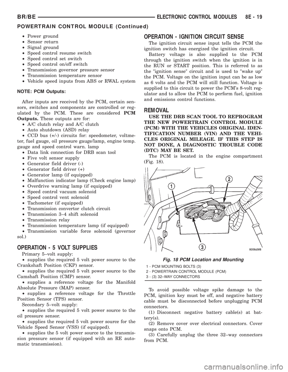
The PCM is located in the engine compartment
(Fig. 18).
To avoid possible voltage spike damage to the
PCM, ignition key must be off, and negative battery
cable must be disconnected before unplugging PCM
connectors.
(1) Disconnect negative battery cable(s) at bat-
tery(s).
(2) Remove cover over electrical connectors. Cover
snaps onto PCM.
(3) Carefully unplug the three 32±way connectors
from PCM.
Fig. 18 PCM Location and Mounting
1 - PCM MOUNTING BOLTS (3)
2 - POWERTRAIN CONTROL MODULE (PCM)
3 - (3) 32±WAY CONNECTORS
BR/BEELECTRONIC CONTROL MODULES 8E - 19
POWERTRAIN CONTROL MODULE (Continued)
Page 538 of 2889
IGNITION CONTROL
TABLE OF CONTENTS
page page
IGNITION CONTROL
DESCRIPTION............................1
OPERATION.............................1
SPECIFICATIONS.........................2
AUTOMATIC SHUT DOWN RELAY
DESCRIPTION............................3
OPERATION.............................3
DIAGNOSIS AND TESTING..................3
ASD AND FUEL PUMP RELAYS.............3
REMOVAL...............................4
INSTALLATION............................5
CAMSHAFT POSITION SENSOR
DESCRIPTION............................5
OPERATION.............................5
REMOVAL...............................7
INSTALLATION............................8
DISTRIBUTOR
DESCRIPTION...........................10
OPERATION.............................11
REMOVAL..............................11
INSTALLATION...........................11
DISTRIBUTOR CAP
DIAGNOSIS AND TESTING.................12
DISTRIBUTOR CAP.....................12DISTRIBUTOR ROTOR
DIAGNOSIS AND TESTING.................13
DISTRIBUTOR ROTOR...................13
IGNITION COIL
DESCRIPTION...........................13
OPERATION.............................14
REMOVAL..............................14
INSTALLATION...........................15
SPARK PLUG
DESCRIPTION...........................16
OPERATION.............................16
DIAGNOSIS AND TESTING.................16
SPARK PLUG CONDITIONS...............16
REMOVAL..............................18
CLEANING..............................19
INSTALLATION...........................19
SPARK PLUG CABLE
DESCRIPTION...........................19
OPERATION.............................19
DIAGNOSIS AND TESTING.................19
SPARK PLUG CABLES...................19
REMOVAL..............................20
INSTALLATION...........................20
IGNITION CONTROL
DESCRIPTION - 8.0L V-10
The ignition system used on the 8.0L V±10 engine
does not use a conventional mechanical distributor.
The system will be referred to as a distributor-less
ignition system.
DESCRIPTION - V-6/V-8
The ignition systems used on the 3.9L V-6, the
5.2L V-8 and the 5.9L V-8 are basically identical.
OPERATION - 8.0L V-10
The ignition coils are individually fired, but each
coil is a dual output. Refer to Ignition Coil for addi-
tional information.
The ignition system is controlled by the Powertrain
Control Module (PCM) on all engines.
The ignition system consists of:
²Spark Plugs
²Ignition Coil packs containing individual coils²Secondary Ignition Cables
²Powertrain Control Module (PCM)
²Also to be considered part of the ignition system
are certain inputs from the Crankshaft Position,
Camshaft Position, Throttle Position and MAP Sen-
sors
OPERATION - V-6/V-8
The ignition system is controlled by the Powertrain
Control Module (PCM) on all engines.
The ignition system consists of:
²Spark Plugs
²Ignition Coil
²Secondary Ignition Cables
²Distributor (contains rotor and camshaft position
sensor)
²Powertrain Control Module (PCM)
²Also to be considered part of the ignition system
are certain inputs from the Crankshaft Position,
Camshaft Position, Throttle Position and MAP Sen-
sors
BR/BEIGNITION CONTROL 8I - 1
Page 551 of 2889
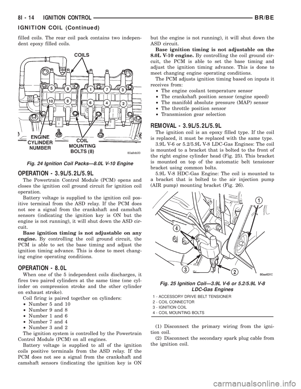
filled coils. The rear coil pack contains two indepen-
dent epoxy filled coils.
OPERATION - 3.9L/5.2L/5.9L
The Powertrain Control Module (PCM) opens and
closes the ignition coil ground circuit for ignition coil
operation.
Battery voltage is supplied to the ignition coil pos-
itive terminal from the ASD relay. If the PCM does
not see a signal from the crankshaft and camshaft
sensors (indicating the ignition key is ON but the
engine is not running), it will shut down the ASD cir-
cuit.
Base ignition timing is not adjustable on any
engine.By controlling the coil ground circuit, the
PCM is able to set the base timing and adjust the
ignition timing advance. This is done to meet chang-
ing engine operating conditions.
OPERATION - 8.0L
When one of the 5 independent coils discharges, it
fires two paired cylinders at the same time (one cyl-
inder on compression stroke and the other cylinder
on exhaust stroke).
Coil firing is paired together on cylinders:
²Number 5 and 10
²Number 9 and 8
²Number 1 and 6
²Number 7 and 4
²Number 3 and 2
The ignition system is controlled by the Powertrain
Control Module (PCM) on all engines.
Battery voltage is supplied to all of the ignition
coils positive terminals from the ASD relay. If the
PCM does not see a signal from the crankshaft and
camshaft sensors (indicating the ignition key is ONbut the engine is not running), it will shut down the
ASD circuit.
Base ignition timing is not adjustable on the
8.0L V-10 engine.By controlling the coil ground cir-
cuit, the PCM is able to set the base timing and
adjust the ignition timing advance. This is done to
meet changing engine operating conditions.
The PCM adjusts ignition timing based on inputs it
receives from:
²The engine coolant temperature sensor
²The crankshaft position sensor (engine speed)
²The manifold absolute pressure (MAP) sensor
²The throttle position sensor
²Transmission gear selection
REMOVAL - 3.9L/5.2L/5.9L
The ignition coil is an epoxy filled type. If the coil
is replaced, it must be replaced with the same type.
3.9L V-6 or 5.2/5.9L V-8 LDC-Gas Engines: The coil
is mounted to a bracket that is bolted to the front of
the right engine cylinder head (Fig. 25). This bracket
is mounted on top of the automatic belt tensioner
bracket using common bolts.
5.9L V-8 HDC-Gas Engine: The coil is mounted to
a bracket that is bolted to the air injection pump
(AIR pump) mounting bracket (Fig. 26).
(1) Disconnect the primary wiring from the igni-
tion coil.
(2) Disconnect the secondary spark plug cable from
the ignition coil.
Fig. 24 Ignition Coil PacksÐ8.0L V-10 Engine
Fig. 25 Ignition CoilÐ3.9L V-6 or 5.2/5.9L V-8
LDC-Gas Engines
1 - ACCESSORY DRIVE BELT TENSIONER
2 - COIL CONNECTOR
3 - IGNITION COIL
4 - COIL MOUNTING BOLTS
8I - 14 IGNITION CONTROLBR/BE
IGNITION COIL (Continued)
Page 594 of 2889
behind the cutout causes the ªWAIT TO STARTº text
to appear in red through the translucent outer layer
of the overlay when the indicator is illuminated from
behind by a Light Emitting Diode (LED) that is sol-
dered onto the instrument cluster electronic circuit
board. The wait-to-start indicator is serviced as a
unit with the instrument cluster.
OPERATION
The wait-to-start indicator gives an indication to
the vehicle operator when the diesel engine intake
air heater is energized in its preheat operating mode.
This indicator is controlled by a hard wired input to
the instrument cluster from the Engine Control Mod-
ule (ECM). The wait-to-start indicator Light Emitting
Diode (LED) receives battery current on the instru-
ment cluster electronic circuit board through the
fused ignition switch output (st-run) circuit whenever
the ignition switch is in the On or Start positions;
therefore, the lamp will always be off when the igni-
tion switch is in any position except On or Start. The
indicator LED only illuminates when it is switched to
ground by the input from the ECM. The ECM will
turn on the wait-to-start indicator by pulling the
wait-to-start indicator driver circuit to ground each
time the ignition switch is turned to the On or Start
positions. The indicator then remains illuminated
until the ECM detects that the air within the intake
manifold is the proper temperature to ensure reliable
and efficient engine starting, until the ECM detects
that the engine is running, or until the ignition
switch is turned to the Off position, whichever occurs
first.
The ECM continually monitors the intake manifold
air temperature sensor, the Manifold Absolute Pres-
sure (MAP) sensor, and many other vehicle condi-
tions to determine when the wait-to-start indicator
should be illuminated. For proper diagnosis of the
wait-to-start indicator, the ECM, or the inputs the
ECM uses to control the wait-to-start indicator oper-
ation, a DRBIIItscan tool is required. Refer to the
appropriate diagnostic information.
WASHER FLUID INDICATOR
DESCRIPTION
A washer fluid indicator is standard equipment on
all instrument clusters. The washer fluid indicator is
located near the lower edge of the instrument cluster
overlay, to the right of center. The washer fluid indi-
cator consists of a stenciled cutout of the words
ªLOW WASHERº in the opaque layer of the instru-
ment cluster overlay. The dark outer layer of the
overlay prevents the indicator from being clearly vis-
ible when it is not illuminated. An amber lens behindthe cutout in the opaque layer of the overlay causes
the ªLOW WASHERº text to appear in amber
through the translucent outer layer of the overlay
when it is illuminated from behind by a Light Emit-
ting Diode (LED) soldered onto the instrument clus-
ter electronic circuit board. The washer fluid
indicator is serviced as a unit with the instrument
cluster.
OPERATION
The washer fluid indicator gives an indication to
the vehicle operator when the fluid level in the
washer fluid reservoir is low. This indicator is con-
trolled by a transistor on the instrument cluster elec-
tronic circuit board based upon cluster programming
and a hard wired washer fluid level switch input to
the cluster. The washer fluid indicator Light Emit-
ting Diode (LED) receives battery current on the
instrument cluster electronic circuit board through
the fused ignition switch output (st-run) circuit
whenever the ignition switch is in the On or Start
positions; therefore, the indicator will always be off
when the ignition switch is in any position except On
or Start. The LED only illuminates when it is pro-
vided a path to ground by the instrument cluster
transistor. The instrument cluster will turn on the
washer fluid indicator for the following reasons:
²Bulb Test- Each time the ignition switch is
turned to the On position the indicator is illuminated
for about two seconds as a bulb test.
²Washer Fluid Level Switch Input- Immedi-
ately after the bulb test, if the cluster senses ground
on the washer fluid switch sense circuit for more
than about thirty seconds, it turns on the washer
fluid indicator. Any time after the bulb test, the clus-
ter must sense ground on the washer fluid switch
sense circuit for more than about sixty seconds before
it turns on the indicator. Once illuminated, the indi-
cator will remain illuminated until the ignition
switch is cycled and the cluster senses an open cir-
cuit on the low washer fluid sense input. This strat-
egy is intended to reduce the effect that fluid
sloshing within the washer reservoir can have on
reliable indicator operation.
²Actuator Test- Each time the cluster is put
through the actuator test, the indicator will be
turned on during the bulb check portion of the test to
confirm the functionality of the LED and the cluster
control circuitry.
The washer fluid level switch is connected in series
between ground and the washer fluid switch sense
input to the instrument cluster. For more informa-
tion on the washer fluid level switch,(Refer to 8 -
ELECTRICAL/WIPERS/WASHERS/WASHER FLUID
LEVEL SWITCH - OPERATION). For further diag-
nosis of the washer fluid indicator or the instrument
BR/BEINSTRUMENT CLUSTER 8J - 35
WAIT-TO-START INDICATOR (Continued)
Page 639 of 2889
while maintaining a speed of 48 kilometers-per-hour
(30 miles-per-hour) or higher.
The thermometer function is supported by an
ambient temperature sensor. The sensor is mounted
outside the passenger compartment near the front
and center of the vehicle, and is hard wired to the
module. The ambient temperature sensor is available
as a separate service item.
STANDARD PROCEDURE - COMPASS
CALIBRATION
CAUTION: Do not place any external magnets, such
as magnetic roof mount antennas, in the vicinity of
the compass. Do not use magnetic tools when ser-
vicing the overhead console.
The electronic compass unit features a self-cali-
brating design, which simplifies the calibration pro-
cedure. This feature automatically updates the
compass calibration while the vehicle is being driven.
This allows the compass unit to compensate for small
changes in the residual magnetism that the vehicle
may acquire during normal use. If the compass read-
ings appear to be erratic or out of calibration, per-
form the following calibration procedure. Also, new
service replacement compass mini-trip computer
modules must have their compass calibrated using
this procedure. Do not attempt to calibrate the com-
pass near large metal objects such as other vehicles,
large buildings, or bridges; or, near overhead or
underground power lines.
(1) Start the engine. If the compass/temperature
data is not currently being displayed, momentarily
depress and release the Step push button to step
through the display options until you have reached
the compass/temperature display.
(2) Depress both the U.S./Metric and the Step
push buttons at the same time for more than six sec-
onds, until ªCALº appears in the display, then release
both push buttons. The ªCALº in the display indi-
cates that the compass is in the calibration mode.
(3) Drive the vehicle on a level surface, at least
fifty feet away from large metal objects and power
lines, in all four compass directions, such as driving
around a city block several times or driving in two to
three complete circles at a slow to medium speed.
(4) When the calibration is successfully completed,
ªCALº will disappear from the display and normal
compass mini-trip computer operation will resume.
NOTE: If the ªCALº message remains in the display,
either there is excessive magnetism near the com-
pass, or the unit is faulty. Repeat the calibration
procedure at least one more time.NOTE: If the wrong direction is still indicated in the
compass display, the area selected for calibration
may be too close to a strong magnetic field. Repeat
the calibration procedure in another location.
STANDARD PROCEDURE - COMPASS
VARIATION ADJUSTMENT
Compass variance, also known as magnetic decli-
nation, is the difference in angle between magnetic
north and true geographic north. In some geographic
locations, the difference between magnetic and geo-
graphic north is great enough to cause the compass
to give false readings. If this problem occurs, the
compass variance must be set. There are two meth-
ods that can be used to enter this information into
the compass mini-trip computer module. They are
the zone method and the direct method.
ZONE METHOD
(1) Using the Variance Settings map, find your
geographic location and note the zone number (Fig.
2).
(2) Turn the ignition switch to the On position. If
the compass/temperature data is not currently being
displayed, momentarily depress and release the Step
push button to step through the display options until
you have reached the compass/temperature display.
(3) Depress both the U.S./Metric and the Step
push buttons at the same time and hold them down
for more than 100 milliseconds, but not more than
one second. The compass mini-trip computer will
enter the variation adjustment mode and ªVARº
along with the current variance zone will appear in
the display.
(4) Momentarily depress and release the Step push
button to step through the zone numbers, until the
zone number for your geographic location appears in
the display.
(5) After five seconds, the displayed zone will auto-
matically be set in the compass mini-trip computer
module memory and normal operation will resume.
(6) Confirm that the correct directions are now
indicated by the compass.
DIRECT METHOD
(1) Turn the vehicle so it is headed in either the
north or south direction. The vehicle must be headed
within 45 degrees of north or south for this procedure
to work. The vehicle may be moving or stationary.
(2) Turn the ignition switch to the On position. If
the compass/temperature data is not currently being
displayed, momentarily depress and release the Step
push button to step through the display options until
you have reached the compass/temperature display.
8M - 4 MESSAGE SYSTEMSBR/BE
OVERHEAD CONSOLE (Continued)
Page 757 of 2889
Component Page
Map Lamps.......................... 8W-49
Outboard Clearance Lamp............... 8W-50
Outboard Headlamp................... 8W-50
Outboard Identification Lamp............ 8W-50
Output Speed Sensor................... 8W-31
Overdrive Switch...................... 8W-31
Overhead Console..................... 8W-49
Oxygen Sensors....................... 8W-30
Park Brake Switch.................. 8W-40, 50
Park/Neutral Position Switch.......... 8W-30, 51
Park/Turn Signal Lamp................. 8W-52
Passenger Airbag On/Off Switch.......... 8W-43
Passenger Airbag...................... 8W-43
Power Distribution Center............... 8W-10
Power Mirror Switch................... 8W-62
Power Mirror......................... 8W-62
Power Outlet......................... 8W-41
Power Seat Front Vertical Motors......... 8W-63
Power Seat Horizontal Motors............ 8W-63
Power Seat Rear Vertical Motor........... 8W-63
Power Seat Switch..................... 8W-63
Power Window Motors.................. 8W-60
Powertrain Control Module.............. 8W-30
PTO Switch.......................... 8W-30
Quad High Beam Relay................. 8W-50
Radio Choke Relay..................... 8W-47Component Page
Radio............................... 8W-47
Remote Radio Switch................... 8W-47
Seat Belt Switch...................... 8W-40
Seat Heat Interface Module.............. 8W-63
Security Relay........................ 8W-39
Speakers............................ 8W-47
Speed Control Servo................... 8W-33
Speed Control Switch................... 8W-33
Splice Information..................... 8W-70
Tail/Stop/Turn Signal Lamp.............. 8W-51
Tailgate Lamp........................ 8W-51
Throttle Position Sensor................ 8W-30
Trailer Tow Connector.................. 8W-54
Trailer Tow Relay...................... 8W-54
Transmission Control Relay.............. 8W-31
Transmission Solenoid Assembly.......... 8W-31
Turn Signal/Hazard Switch.............. 8W-52
Underhood Lamp...................... 8W-44
Visor/Vanity Lamp..................... 8W-44
Washer Fluid Level Switch.............. 8W-40
Water In Fuel Sensor................... 8W-30
Wheel Speed Sensors................ 8W-34, 35
Windshield Washer Pump............... 8W-53
Wiper Motor Relay..................... 8W-53
Wiper Motor.......................... 8W-53
BR/BE8W-02 COMPONENT INDEX 8W - 02 - 1