oil temperature DODGE RAM 2001 Service Repair Manual
[x] Cancel search | Manufacturer: DODGE, Model Year: 2001, Model line: RAM, Model: DODGE RAM 2001Pages: 2889, PDF Size: 68.07 MB
Page 7 of 2889
FASTENER USAGE
DESCRIPTION - FASTENER USAGE
WARNING: USE OF AN INCORRECT FASTENER
MAY RESULT IN COMPONENT DAMAGE OR PER-
SONAL INJURY.
Figure art, specifications and torque references in
this Service Manual are identified in metric and SAE
format.
During any maintenance or repair procedures, it is
important to salvage all fasteners (nuts, bolts, etc.)
for reassembly. If the fastener is not salvageable, a
fastener of equivalent specification must be used.
DESCRIPTION - THREADED HOLE REPAIR
Most stripped threaded holes can be repaired using
a Helicoilt. Follow the manufactures recommenda-
tions for application and repair procedures.
INTERNATIONAL VEHICLE
CONTROL & DISPLAY
SYMBOLS
DESCRIPTION - INTERNATIONAL SYMBOLS
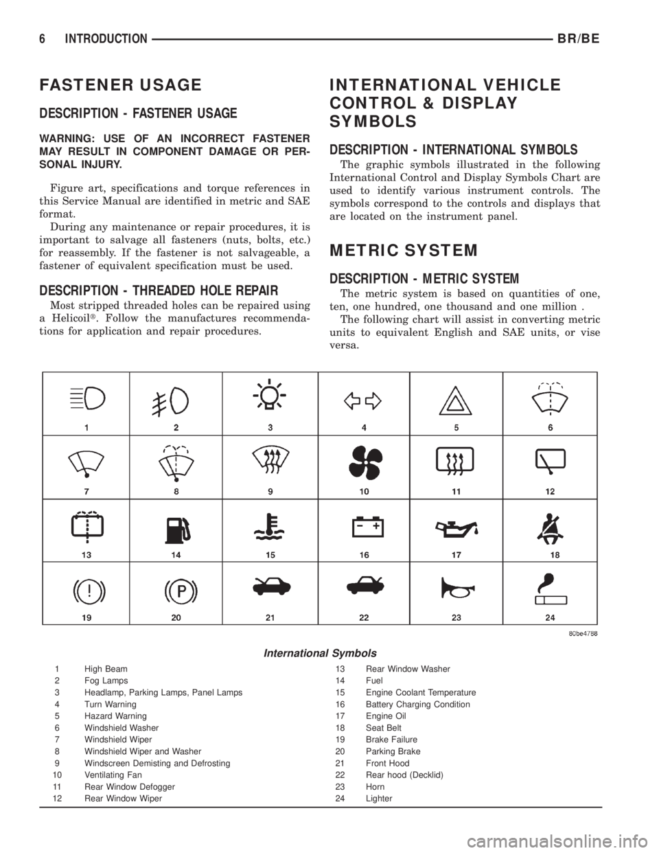
The graphic symbols illustrated in the following
International Control and Display Symbols Chart are
used to identify various instrument controls. The
symbols correspond to the controls and displays that
are located on the instrument panel.
METRIC SYSTEM
DESCRIPTION - METRIC SYSTEM
The metric system is based on quantities of one,
ten, one hundred, one thousand and one million .
The following chart will assist in converting metric
units to equivalent English and SAE units, or vise
versa.
International Symbols
1 High Beam 13 Rear Window Washer
2 Fog Lamps 14 Fuel
3 Headlamp, Parking Lamps, Panel Lamps 15 Engine Coolant Temperature
4 Turn Warning 16 Battery Charging Condition
5 Hazard Warning 17 Engine Oil
6 Windshield Washer 18 Seat Belt
7 Windshield Wiper 19 Brake Failure
8 Windshield Wiper and Washer 20 Parking Brake
9 Windscreen Demisting and Defrosting 21 Front Hood
10 Ventilating Fan 22 Rear hood (Decklid)
11 Rear Window Defogger 23 Horn
12 Rear Window Wiper 24 Lighter
6 INTRODUCTIONBR/BE
Page 16 of 2889
INTERNATIONAL SYMBOLS
DESCRIPTION
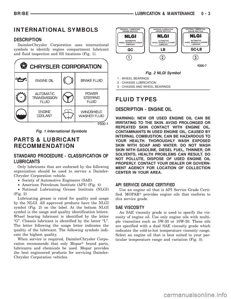
DaimlerChrysler Corporation uses international
symbols to identify engine compartment lubricant
and fluid inspection and fill locations (Fig. 1).
PARTS & LUBRICANT
RECOMMENDATION
STANDARD PROCEDURE - CLASSIFICATION OF
LUBRICANTS
Only lubricants that are endorsed by the following
organization should be used to service a Daimler-
Chrysler Corporation vehicle.
²Society of Automotive Engineers (SAE)
²American Petroleum Institute (API) (Fig. 4)
²National Lubricating Grease Institute (NLGI)
(Fig. 2)
Lubricating grease is rated for quality and usage
by the NLGI. All approved products have the NLGI
symbol (Fig. 2) on the label. At the bottom NLGI
symbol is the usage and quality identification letters.
Wheel bearing lubricant is identified by the letter
ªGº. Chassis lubricant is identified by the latter ªLº.
The letter following the usage letter indicates the
quality of the lubricant. The following symbols indi-
cate the highest quality.
When service is required, DaimlerChrysler Corpo-
ration recommends that only Mopartbrand parts,
lubricants and chemicals be used. Mopar provides
the best engineered products for servicing Daimler-
Chrysler Corporation vehicles.
FLUID TYPES
DESCRIPTION - ENGINE OIL
WARNING: NEW OR USED ENGINE OIL CAN BE
IRRITATING TO THE SKIN. AVOID PROLONGED OR
REPEATED SKIN CONTACT WITH ENGINE OIL.
CONTAMINANTS IN USED ENGINE OIL, CAUSED BY
INTERNAL COMBUSTION, CAN BE HAZARDOUS TO
YOUR HEALTH. THOROUGHLY WASH EXPOSED
SKIN WITH SOAP AND WATER. DO NOT WASH
SKIN WITH GASOLINE, DIESEL FUEL, THINNER, OR
SOLVENTS, HEALTH PROBLEMS CAN RESULT. DO
NOT POLLUTE, DISPOSE OF USED ENGINE OIL
PROPERLY. CONTACT YOUR DEALER OR GOVERN-
MENT AGENCY FOR LOCATION OF COLLECTION
CENTER IN YOUR AREA.
API SERVICE GRADE CERTIFIED
Use an engine oil that is API Service Grade Certi-
fied. MOPARtprovides engine oils that conform to
this service grade.
SAE VISCOSITY
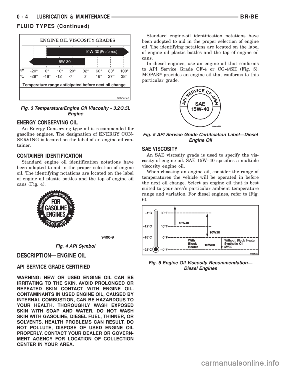
An SAE viscosity grade is used to specify the vis-
cosity of engine oil. Use only engine oils with multi-
ple viscosities such as 5W-30 or 10W-30. These oils
are specified with a dual SAE viscosity grade which
indicates the cold-to-hot temperature viscosity range.
Select an engine oil that is best suited to your par-
ticular temperature range and variation (Fig. 3).
Fig. 1 International Symbols
Fig. 2 NLGI Symbol
1 - WHEEL BEARINGS
2 - CHASSIS LUBRICATION
3 - CHASSIS AND WHEEL BEARINGS
BR/BELUBRICATION & MAINTENANCE 0 - 3
Page 17 of 2889
ENERGY CONSERVING OIL
An Energy Conserving type oil is recommended for
gasoline engines. The designation of ENERGY CON-
SERVING is located on the label of an engine oil con-
tainer.
CONTAINER IDENTIFICATION
Standard engine oil identification notations have
been adopted to aid in the proper selection of engine
oil. The identifying notations are located on the label
of engine oil plastic bottles and the top of engine oil
cans (Fig. 4).
DESCRIPTIONÐENGINE OIL
API SERVICE GRADE CERTIFIED
WARNING: NEW OR USED ENGINE OIL CAN BE
IRRITATING TO THE SKIN. AVOID PROLONGED OR
REPEATED SKIN CONTACT WITH ENGINE OIL.
CONTAMINANTS IN USED ENGINE OIL, CAUSED BY
INTERNAL COMBUSTION, CAN BE HAZARDOUS TO
YOUR HEALTH. THOROUGHLY WASH EXPOSED
SKIN WITH SOAP AND WATER. DO NOT WASH
SKIN WITH GASOLINE, DIESEL FUEL, THINNER, OR
SOLVENTS, HEALTH PROBLEMS CAN RESULT. DO
NOT POLLUTE, DISPOSE OF USED ENGINE OIL
PROPERLY. CONTACT YOUR DEALER OR GOVERN-
MENT AGENCY FOR LOCATION OF COLLECTION
CENTER IN YOUR AREA.Standard engine-oil identification notations have
been adopted to aid in the proper selection of engine
oil. The identifying notations are located on the label
of engine oil plastic bottles and the top of engine oil
cans.
In diesel engines, use an engine oil that conforms
to API Service Grade CF-4 or CG-4/SH (Fig. 5).
MOPARtprovides an engine oil that conforms to this
particular grade.
SAE VISCOSITY
An SAE viscosity grade is used to specify the vis-
cosity of engine oil. SAE 15W±40 specifies a multiple
viscosity engine oil.
When choosing an engine oil, consider the range of
temperatures the vehicle will be operated in before
the next oil change. Select an engine oil that is best
suited to your area's particular ambient temperature
range and variation. For diesel engines, refer to (Fig.
6).
Fig. 3 Temperature/Engine Oil Viscosity - 3.2/3.5L
Engine
Fig. 4 API Symbol
Fig. 5 API Service Grade Certification LabelÐDiesel
Engine Oil
Fig. 6 Engine Oil Viscosity RecommendationÐ
Diesel Engines
0 - 4 LUBRICATION & MAINTENANCEBR/BE
FLUID TYPES (Continued)
Page 18 of 2889
DESCRIPTION
A multi-purpose, hypoid gear lubricant which con-
forms to the following specifications should be used.
Mopar Hypoid Gear Lubricant conforms to all of
these specifications.
SAE ratings also apply to multiple grade gear
lubricants. In addition, API classification defines the
lubricants usage.
FRONT AXLE
²The lubricant should have MIL-L-2105C and
API GL 5 quality specifications.
²Lubricant is SAE 75W-140 SYNTHETIC gear
lubricant.
REAR AXLE
²The lubricant should have MIL-L-2105C and
API GL 5 quality specifications.
²Lubricant is a thermally stable SAE 80W-90
gear lubricant.
²Lubricant for axles intended for heavy-duty or
trailer tow use is SAE 75W-140 SYNTHETIC gear
lubricant.
NOTE: Trac-lokYand Vari-lokYequipped axles
require a friction modifier be added to the lubricant.
CAUTION: If axle is submerged in water, lubricant
must be replaced immediately to avoid possible
premature axle failure.
DESCRIPTION - TRANSFER CASE FLUID
Recommended lubricant for the NV231 and NV241
transfer case is MopartATF +4, (MS 9602) Auto-
matic Transmission Fluid.
DESCRIPTION - AUTOMATIC TRANSMISSION
FLUID
NOTE: Refer to the maintenance schedules in this
group for the recommended maintenance (fluid/filter
change) intervals for this transmission.
NOTE: Refer to Service Procedures in this group for
fluid level checking procedures.
MopartATF +4, type 9602, Automatic Transmis-
sion Fluid is the recommended fluid for Daimler-
Chrysler automatic transmissions.
Dexron II fluid IS NOT recommended. Clutch
chatter can result from the use of improper
fluid.MopartATF +4, type 9602, Automatic Transmis-
sion Fluid when new is red in color. The ATF is dyed
red so it can be identified from other fluids used in
the vehicle such as engine oil or antifreeze. The red
color is not permanent and is not an indicator of fluid
condition. As the vehicle is driven, the ATF will begin
to look darker in color and may eventually become
brown.This is normal.A dark brown/black fluid
accompanied with a burnt odor and/or deterioration
in shift quality may indicate fluid deterioration or
transmission component failure.
FLUID ADDITIVES
DaimlerChrysler strongly recommends against the
addition of any fluids to the transmission, other than
those automatic transmission fluids listed above.
Exceptions to this policy are the use of special dyes
to aid in detecting fluid leaks.
Various ªspecialº additives and supplements exist
that claim to improve shift feel and/or quality. These
additives and others also claim to improve converter
clutch operation and inhibit overheating, oxidation,
varnish, and sludge. These claims have not been sup-
ported to the satisfaction of DaimlerChrysler and
these additivesmust not be used.The use of trans-
mission ªsealersº should also be avoided, since they
may adversely affect the integrity of transmission
seals.
OPERATION - AUTOMATIC TRANSMISSION
FLUID
The automatic transmission fluid is selected based
upon several qualities. The fluid must provide a high
level of protection for the internal components by
providing a lubricating film between adjacent metal
components. The fluid must also be thermally stable
so that it can maintain a consistent viscosity through
a large temperature range. If the viscosity stays con-
stant through the temperature range of operation,
transmission operation and shift feel will remain con-
sistent. Transmission fluid must also be a good con-
ductor of heat. The fluid must absorb heat from the
internal transmission components and transfer that
heat to the transmission case.
BR/BELUBRICATION & MAINTENANCE 0 - 5
FLUID TYPES (Continued)
Page 22 of 2889
105,000 Miles (168 000 km) or at 84 months
²Inspect auto tension drive belt and replace if
required.**
²Change engine oil.
²Replace engine oil filter.
²Inspect engine coolant level, hoses, and clamps.
²Inspect brake hoses.
²Lubricate the steering linkages.
²Check manual transmission fluid level.
²Inspect exhaust system.
112,500 Miles (180 000 km) or at 90 months
²Change engine oil.
²Replace engine oil filter.
²Inspect engine coolant level, hoses, and clamps.
²Flush and replace engine coolant if it has been
30,000 miles (48 000 km) or 24 months since last
change.
²Inspect brake hoses.
²Inspect brake linings.
²Inspect front wheel bearings. Clean and repack,
if required (4x2).
²Lubricate the steering linkages.
²Lubricate non permanently sealed ball joints.
²Check manual transmission fluid level.
²Drain and refill transfer case fluid.
²Inspect exhaust system.
120,000 Miles (192 000 km) or at 96 months
²Replace engine air cleaner element.
²Replace ignition cables.
²Check PCV valve and replace as neces-
sary.*
²Replace spark plugs.
²Inspect auto tension drive belt and replace if
required.**
²Change engine oil.
²Replace engine oil filter.
²Inspect engine coolant level, hoses, and clamps.
²Inspect brake hoses.
²Lubricate the steering linkages.
²Check manual transmission fluid level.
²Inspect exhaust system.
*This maintenance is recommended by Daimler-
Chrysler to the customer but it is not required to
maintain warranty on the PCV valve.
**This maintenance is not required if the belt was
previously replaced.
LIGHT DUTY SCHEDULE ªBº
Follow this schedule if the vehicle is usually oper-
ated under one or more of the following conditions.
²Frequent short trips of less than 5 miles.
²Frequent driving in dusty conditions.
²Trailer towing.
²Frequent long periods of engine idling.²More than 50 percent of the driving is at sus-
tained high speeds during hot weather, above 90ÉF
(32ÉC).
²Frequent stop and go driving.
²Day and night temperatures are below freezing.
²Taxi, police or delivery service (commercial ser-
vice).
²Off-road or desert operation.
3,000 Miles (5 000 km)
²Change engine oil.
²Replace engine oil filter.
²Inspect engine coolant level, hoses, and clamps.
²Inspect brake hoses.
²Lubricate the steering linkages.
²Check manual transmission fluid level.
²Inspect exhaust system.
6,000 Miles (10 000 km)
²Change engine oil.
²Replace engine oil filter.
²Inspect engine coolant level, hoses, and clamps.
²Inspect brake hoses.
²Lubricate the steering linkages.
²Check manual transmission fluid level.
²Inspect exhaust system.
9,000 Miles (14 000 km)
²Change engine oil.
²Replace engine oil filter.
²Inspect engine coolant level, hoses, and clamps.
²Inspect brake hoses.
²Lubricate the steering linkages.
²Check manual transmission fluid level.
²Inspect exhaust system.
12,000 Miles (19 000 km)
²Change engine oil.
²Replace engine oil filter.
²Inspect engine coolant level, hoses, and clamps.
²Inspect brake hoses.
²Inspect brake linings.
²Lubricate the steering linkages.
²Check manual transmission fluid level.
²Change rear axle fluid.
²Change front axle fluid (4x4).
²Inspect exhaust system.
15,000 Miles (24 000 km)
²Inspect engine air cleaner element, replace
as necessary.
²Change engine oil.
²Replace engine oil filter.
²Inspect engine coolant level, hoses, and clamps.
²Inspect brake hoses.
²Lubricate the steering linkages.
²Check manual transmission fluid level.
BR/BELUBRICATION & MAINTENANCE 0 - 9
MAINTENANCE SCHEDULES (Continued)
Page 336 of 2889
COOLING
TABLE OF CONTENTS
page page
COOLING
DESCRIPTION............................1
OPERATION.............................2
DIAGNOSIS AND TESTING..................4
PRELIMINARY CHECKS...................4
ON-BOARD DIAGNOSTICS (OBD)...........4
COOLING SYSTEM LEAKS................5
COOLING SYSTEM GAS ENGINE...........7
COOLING SYSTEM DIESEL ENGINE........12
STANDARD PROCEDURE..................15
DRAINING COOLING SYSTEM - 3.9L/5.2L/
5.9L/8.0L ENGINES......................15
DRAINING COOLING SYSTEM - 5.9L
DIESEL ENGINE........................15REFILLING COOLING SYSTEM - 3.9L/5.2L/
5.9L/8.0L ENGINES......................15
REFILLING COOLING SYSTEM - 5.9L
DIESEL ENGINE........................15
ADDING ADDITIONAL COOLANT...........16
COOLANT LEVEL CHECK................16
COOLING SYSTEM CLEANING/REVERSE
FLUSHING............................16
COOLANT SELECTION-ADDITIVES.........17
SPECIFICATIONS........................17
SPECIAL TOOLS.........................18
ACCESSORY DRIVE......................19
ENGINE................................39
TRANSMISSION.........................79
COOLING
DESCRIPTIONÐCOOLING SYSTEM FLOW -
3.9L/5.2L/5.9L ENGINE
The cooling system regulates engine operating tem-
perature. It allows the engine to reach normal oper-
ating temperature as quickly as possible. It also
maintains normal operating temperature and pre-
vents overheating.
The cooling system also provides a means of heat-
ing the passenger compartment and cooling the auto-
matic transmission fluid (if equipped). The cooling
system is pressurized and uses a centrifugal water
pump to circulate coolant throughout the system.
An optional factory installed maximum duty cool-
ing package is available on most models. This pack-
age will provide additional cooling capacity forvehicles used under extreme conditions such as
trailer towing in high ambient temperatures (Fig. 1).
DESCRIPTIONÐCOOLING SYSTEM FLOW -
5.9L DIESEL
The diesel engine cooling system consists of (Fig.
2):
²Cross-flow radiator
²Belt driven water pump
²Belt driven mechanical cooling fan
²Thermal viscous fan drive
²Fan shroud
²Radiator pressure cap
²Vertically mounted thermostat
²Coolant reserve/recovery system
²Transmission oil cooler
²Coolant
BR/BECOOLING 7 - 1
Page 344 of 2889
CONDITION POSSIBLE CAUSES CORRECTION
16. Thermostat partially or completely
shut.16. Check thermostat operation and
replace as necessary. (Refer to 7 -
COOLING/ENGINE/ENGINE COOLANT
THERMOSTAT - REMOVAL) .
17. Viscous fan drive not operating
properly.17. Check fan drive operation and replace
as necessary. (Refer to 7 - COOLING/
ENGINE/FAN DRIVE VISCOUS CLUTCH
- REMOVAL) .
18. Cylinder head gasket leaking. 18. Check for cylinder head gasket leaks.
(Refer to 7 - COOLING - DIAGNOSIS
AND TESTING).
19. Heater core leaking. 19. Check heater core for leaks. (Refer to
24 - HEATING & AIR CONDITIONING/
PLUMBING - DIAGNOSIS AND
TESTING). Repair as necessary.
TEMPERATURE
GAUGE READING IS
INCONSISTENT
(FLUCTUATES,
CYCLES OR IS
ERRATIC)1. During cold weather operation, with the
heater blower in the high position, the
gauge reading may drop slightly.1. A normal condition. No correction is
necessary.
2. Temperature gauge or engine mounted
gauge sensor defective or shorted. Also,
corroded or loose wiring in this circuit.2. Check operation of gauge and repair if
necessary. (Refer to 8 - ELECTRICAL/
INSTRUMENT CLUSTER - DIAGNOSIS
AND TESTING).
3. Gauge reading rises when vehicle is
brought to a stop after heavy use (engine
still running)3. A normal condition. No correction is
necessary. Gauge should return to normal
range after vehicle is driven.
4. Gauge reading high after re-starting a
warmed up (hot) engine.4. A normal condition. No correction is
necessary. The gauge should return to
normal range after a few minutes of
engine operation.
5. Coolant level low in radiator (air will
build up in the cooling system causing
the thermostat to open late).5. Check and correct coolant leaks. (Refer
to 7 - COOLING - DIAGNOSIS AND
TESTING).
6. Cylinder head gasket leaking allowing
exhaust gas to enter cooling system
causing a thermostat to open late.6. (a) Check for cylinder head gasket
leaks. (Refer to 7 - COOLING -
DIAGNOSIS AND TESTING).
(b) Check for coolant in the engine oil.
Inspect for white steam emitting from the
exhaust system. Repair as necessary.
7. Water pump impeller loose on shaft. 7. Check water pump and replace as
necessary. (Refer to 7 - COOLING/
ENGINE/WATER PUMP - REMOVAL).
8. Loose accessory drive belt. (water
pump slipping)8. (Refer to 7 - COOLING/ACCESSORY
DRIVE/DRIVE BELTS - DIAGNOSIS AND
TESTING). Check and correct as
necessary.
9. Air leak on the suction side of the
water pump allows air to build up in
cooling system causing thermostat to
open late.9. Locate leak and repair as necessary.
BR/BECOOLING 7 - 9
COOLING (Continued)
Page 375 of 2889
DIAGNOSIS AND TESTING.................63
RADIATOR COOLANT FLOW..............63
REMOVAL..............................63
CLEANING..............................65
INSPECTION............................65
INSTALLATION...........................65
RADIATOR PRESSURE CAP
DESCRIPTION...........................65
OPERATION.............................65
DIAGNOSIS AND TESTING.................66
RADIATOR CAP-TO-FILLER NECK SEAL.....66
RADIATOR CAP........................66
CLEANING..............................66
INSPECTION............................66
WATER PUMP - 3.9L/5.2L/5.9L
DESCRIPTION...........................67
OPERATION.............................67
DIAGNOSIS AND TESTING.................67
WATER PUMP.........................67
REMOVAL..............................67
CLEANING..............................69INSPECTION............................69
INSTALLATION...........................70
WATER PUMP - 8.0L
DIAGNOSIS AND TESTING.................70
WATER PUMP.........................70
REMOVAL..............................70
CLEANING..............................72
INSPECTION............................72
INSTALLATION...........................72
WATER PUMP - 5.9L DIESEL
DESCRIPTION...........................73
OPERATION.............................73
DIAGNOSIS AND TESTING.................73
WATER PUMP.........................73
REMOVAL..............................73
CLEANING..............................73
INSPECTION............................73
INSTALLATION...........................74
WATER PUMP INLET TUBE - 3.9L/5.2L/5.9L
REMOVAL..............................74
INSTALLATION...........................77
COOLANT
DESCRIPTION
ETHYLENE-GLYCOL MIXTURES
CAUTION: Richer antifreeze mixtures cannot be
measured with normal field equipment and can
cause problems associated with 100 percent ethyl-
ene-glycol.
The required ethylene-glycol (antifreeze) and water
mixture depends upon the climate and vehicle oper-
ating conditions. The recommended mixture of 50/50
ethylene-glycol and water will provide protection
against freezing to -37 deg. C (-35 deg. F). The anti-
freeze concentrationmust alwaysbe a minimum of
44 percent, year-round in all climates.If percentage
is lower than 44 percent, engine parts may be
eroded by cavitation, and cooling system com-
ponents may be severely damaged by corrosion.
Maximum protection against freezing is provided
with a 68 percent antifreeze concentration, which
prevents freezing down to -67.7 deg. C (-90 deg. F). A
higher percentage will freeze at a warmer tempera-
ture. Also, a higher percentage of antifreeze can
cause the engine to overheat because the specific
heat of antifreeze is lower than that of water.
Use of 100 percent ethylene-glycol will cause for-
mation of additive deposits in the system, as the cor-
rosion inhibitive additives in ethylene-glycol require
the presence of water to dissolve. The deposits act as
insulation, causing temperatures to rise to as high as
149 deg. C (300) deg. F). This temperature is hot
enough to melt plastic and soften solder. Theincreased temperature can result in engine detona-
tion. In addition, 100 percent ethylene-glycol freezes
at 22 deg. C (-8 deg. F ).
PROPYLENE-GLYCOL MIXTURES
It's overall effective temperature range is smaller
than that of ethylene-glycol. The freeze point of 50/50
propylene-glycol and water is -32 deg. C (-26 deg. F).
5 deg. C higher than ethylene-glycol's freeze point.
The boiling point (protection against summer boil-
over) of propylene-glycol is 125 deg. C (257 deg. F )
at 96.5 kPa (14 psi), compared to 128 deg. C (263
deg. F) for ethylene-glycol. Use of propylene-glycol
can result in boil-over or freeze-up on a cooling sys-
tem designed for ethylene-glycol. Propylene glycol
also has poorer heat transfer characteristics than
ethylene glycol. This can increase cylinder head tem-
peratures under certain conditions.
Propylene-glycol/ethylene-glycol Mixtures can cause
the destabilization of various corrosion inhibitors,
causing damage to the various cooling system compo-
nents. Also, once ethylene-glycol and propylene-glycol
based coolants are mixed in the vehicle, conventional
methods of determining freeze point will not be accu-
rate. Both the refractive index and specific gravity dif-
fer between ethylene glycol and propylene glycol.
OPERATION
Coolant flows through the engine block absorbing the
heat from the engine, then flows to the radiator where
the cooling fins in the radiator transfers the heat from
the coolant to the atmosphere. During cold weather the
ethylene-glycol coolant prevents water present in the
cooling system from freezing within temperatures indi-
cated by mixture ratio of coolant to water.
7 - 40 ENGINEBR/BE
Page 376 of 2889
COOLANT RECOVERY
CONTAINER - 3.9L/5.2L/5.9L/
5.9L DIESEL
DESCRIPTION
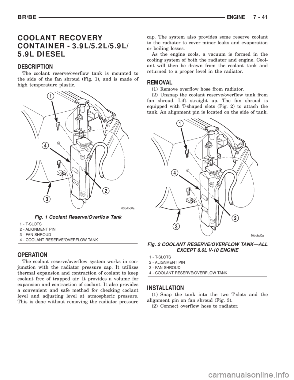
The coolant reserve/overflow tank is mounted to
the side of the fan shroud (Fig. 1), and is made of
high temperature plastic.
OPERATION
The coolant reserve/overflow system works in con-
junction with the radiator pressure cap. It utilizes
thermal expansion and contraction of coolant to keep
coolant free of trapped air. It provides a volume for
expansion and contraction of coolant. It also provides
a convenient and safe method for checking coolant
level and adjusting level at atmospheric pressure.
This is done without removing the radiator pressurecap. The system also provides some reserve coolant
to the radiator to cover minor leaks and evaporation
or boiling losses.
As the engine cools, a vacuum is formed in the
cooling system of both the radiator and engine. Cool-
ant will then be drawn from the coolant tank and
returned to a proper level in the radiator.
REMOVAL
(1) Remove overflow hose from radiator.
(2) Unsnap the coolant reserve/overflow tank from
fan shroud. Lift straight up. The fan shroud is
equipped with T-shaped slots (Fig. 2) to attach the
tank. An alignment pin is located on the side of tank.
INSTALLATION
(1) Snap the tank into the two T-slots and the
alignment pin on fan shroud (Fig. 3).
(2) Connect overflow hose to radiator.
Fig. 1 Coolant Reserve/Overflow Tank
1 - T-SLOTS
2 - ALIGNMENT PIN
3 - FAN SHROUD
4 - COOLANT RESERVE/OVERFLOW TANK
Fig. 2 COOLANT RESERVE/OVERFLOW TANKÐALL
EXCEPT 8.0L V-10 ENGINE
1 - T-SLOTS
2 - ALIGNMENT PIN
3 - FAN SHROUD
4 - COOLANT RESERVE/OVERFLOW TANK
BR/BEENGINE 7 - 41
Page 380 of 2889
(3) Inspect fan assembly for cracks, bends, loose
rivets or broken welds. Replace fan if any damage is
found.
INSTALLATION
(1) Install fan blade assembly to viscous fan drive.
Tighten mounting bolts to 23 N´m (17 ft. lbs.) torque.
(2) Position the fan shroud and fan blade/viscous
fan drive to the vehicle as an assembly.
(3) Install viscous fan drive assembly on fan hub
shaft (Fig. 7). Tighten mounting nut to 57 N´m (42 ft.
lbs.) torque.
(4) Install fan shroud bolts into position and
tighten the mounting bolts to 6 N´m (50 in. lbs.)
torque.
(5) Connect the battery negative cables.
NOTE: Viscous Fan Drive Fluid Pump Out Require-
ment: After installing a new viscous fan drive, bring
the engine speed up to approximately 2000 rpm and
hold for approximately two minutes. This will
ensure proper fluid distribution within the drive.
ENGINE BLOCK HEATER -
3.9L/5.2L/5.9L
DESCRIPTION
WARNING: DO NOT OPERATE ENGINE UNLESS
BLOCK HEATER CORD HAS BEEN DISCONNECTED
FROM POWER SOURCE AND SECURED IN PLACE.
THE POWER CORD MUST BE SECURED IN ITS
RETAINING CLIPS AND ROUTED AWAY FROM
EXHAUST MANIFOLDS AND MOVING PARTS.
An optional engine block heater is available on all
models. The heater is equipped with a power cord.
The heater is mounted in a core hole of the engine
cylinder block (in place of a freeze plug) with the
heating element immersed in engine coolant. The
cord is attached to an engine compartment compo-
nent with tie-straps.
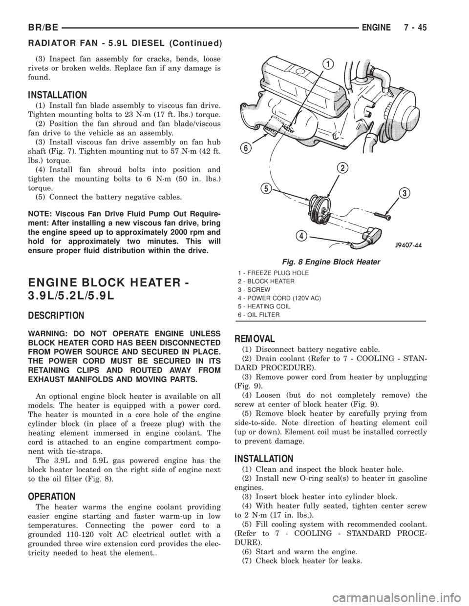
The 3.9L and 5.9L gas powered engine has the
block heater located on the right side of engine next
to the oil filter (Fig. 8).
OPERATION
The heater warms the engine coolant providing
easier engine starting and faster warm-up in low
temperatures. Connecting the power cord to a
grounded 110-120 volt AC electrical outlet with a
grounded three wire extension cord provides the elec-
tricity needed to heat the element..
REMOVAL
(1) Disconnect battery negative cable.
(2) Drain coolant (Refer to 7 - COOLING - STAN-
DARD PROCEDURE).
(3) Remove power cord from heater by unplugging
(Fig. 9).
(4) Loosen (but do not completely remove) the
screw at center of block heater (Fig. 9).
(5) Remove block heater by carefully prying from
side-to-side. Note direction of heating element coil
(up or down). Element coil must be installed correctly
to prevent damage.
INSTALLATION
(1) Clean and inspect the block heater hole.
(2) Install new O-ring seal(s) to heater in gasoline
engines.
(3) Insert block heater into cylinder block.
(4) With heater fully seated, tighten center screw
to 2 N´m (17 in. lbs.).
(5) Fill cooling system with recommended coolant.
(Refer to 7 - COOLING - STANDARD PROCE-
DURE).
(6) Start and warm the engine.
(7) Check block heater for leaks.
Fig. 8 Engine Block Heater
1 - FREEZE PLUG HOLE
2 - BLOCK HEATER
3 - SCREW
4 - POWER CORD (120V AC)
5 - HEATING COIL
6 - OIL FILTER
BR/BEENGINE 7 - 45
RADIATOR FAN - 5.9L DIESEL (Continued)