seats DODGE RAM 2001 Service Repair Manual
[x] Cancel search | Manufacturer: DODGE, Model Year: 2001, Model line: RAM, Model: DODGE RAM 2001Pages: 2889, PDF Size: 68.07 MB
Page 54 of 2889
(5) Install the steering knuckle on the lower ball
joint. Install the lower ball joint nut and tighten to:
²LD: 129 N´m (95 ft. lbs.)
²HD: 136 N´m (110 ft. lbs.)
(5) Install the lower ball joint cotter pin.
(6) Install the stabilizer bar link on the lower sus-
pension arm. Install the grommet, retainer and nut
and tighten to 37 N´m (27 ft. lbs.).
(7) Install the tie rod end on the steering knuckle
and tighten nut to 108 N´m (80 ft. lbs.). Install cotter
pin.
(8) Install the brake rotor and caliper assembly,
(Refer to 5 - BRAKES/HYDRAULIC/MECHANICAL/
ROTORS - INSTALLATION).
(9) Install the tire and wheel assembly, (Refer to
22 - TIRES/WHEELS/WHEELS - STANDARD PRO-
CEDURE).
(10) Remove the support and lower the vehicle.
(11) Tighten the suspension arm crossmember
nuts to 169 N´m (125 ft. lbs.).
SHOCK
DESCRIPTION
The top of the shocks mounts on frame brackets
using grommets. The bottom of the shock is bolted to
the lower suspension arms.
OPERATION
The shock absorbers dampen jounce and rebound
of the vehicle over various road conditions.
DIAGNOSIS AND TESTING - SHOCK
A knocking or rattling noise from a shock absorber
may be caused by movement between mounting
bushings and metal brackets or attaching compo-
nents. These noises can usually be stopped by tight-
ening the attaching nuts. If the noise persists,
inspect for damaged and worn bushings, and attach-
ing components. Repair as necessary if any of these
conditions exist.
A squeaking noise from the shock absorber may be
caused by the hydraulic valving and may be intermit-
tent. This condition is not repairable and the shock
absorber must be replaced.
The shock absorbers are not refillable or adjust-
able. If a malfunction occurs, the shock absorber
must be replaced. To test a shock absorber, hold it in
an upright position and force the piston in and out of
the cylinder four or five times. The action throughout
each stroke should be smooth and even.
The shock absorber bushings do not require any
type of lubrication. Do not attempt to stop bushing
noise by lubricating them. Grease and mineral oil-
base lubricants will deteriorate the bushing.
REMOVAL
(1) Raise and support vehicle.
(2) Remove shock upper nut and remove retainer
and grommet.
(3) Remove lower mounting bolt from suspension
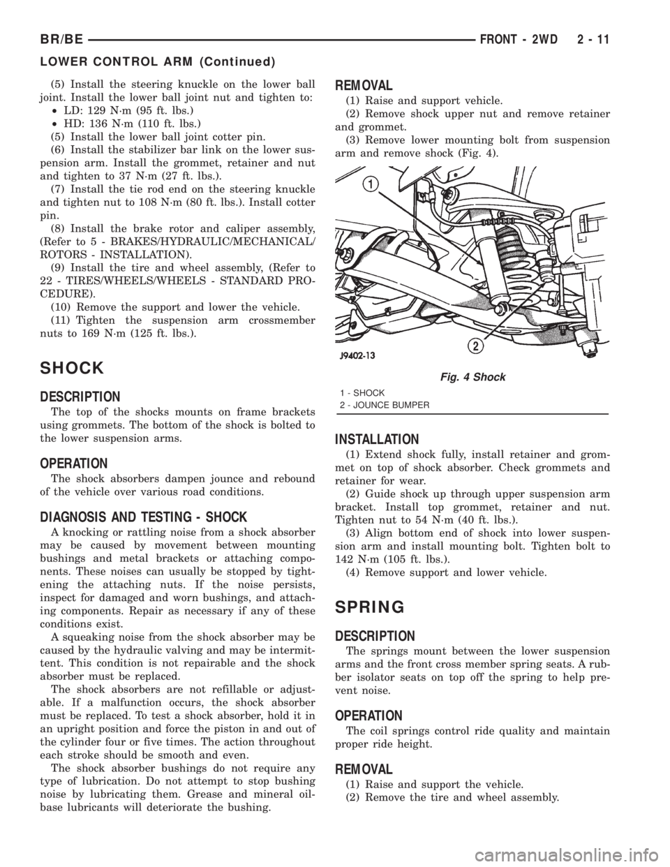
arm and remove shock (Fig. 4).
INSTALLATION
(1) Extend shock fully, install retainer and grom-
met on top of shock absorber. Check grommets and
retainer for wear.
(2) Guide shock up through upper suspension arm
bracket. Install top grommet, retainer and nut.
Tighten nut to 54 N´m (40 ft. lbs.).
(3) Align bottom end of shock into lower suspen-
sion arm and install mounting bolt. Tighten bolt to
142 N´m (105 ft. lbs.).
(4) Remove support and lower vehicle.
SPRING
DESCRIPTION
The springs mount between the lower suspension
arms and the front cross member spring seats. A rub-
ber isolator seats on top off the spring to help pre-
vent noise.
OPERATION
The coil springs control ride quality and maintain
proper ride height.
REMOVAL
(1) Raise and support the vehicle.
(2) Remove the tire and wheel assembly.
Fig. 4 Shock
1 - SHOCK
2 - JOUNCE BUMPER
BR/BEFRONT - 2WD 2 - 11
LOWER CONTROL ARM (Continued)
Page 65 of 2889
(4) Install upper grommet and retainer. Install
upper shock nut and tighten to 47 N´m (35 ft. lbs).
SPRING
DESCRIPTION
The springs use a rubber isolators between the
frame bracket and spring. The isolators help prevent
road noise. The bottom of the spring sits on a seat
mounted to the axle.
OPERATION
The coil springs control ride quality and maintain
proper ride height.
REMOVAL
(1) Raise and support the vehicle. Position a
hydraulic jack under the axle to support it.
(2) Paint or scribe alignment marks on lower sus-
pension arm cam adjusters and axle bracket for
installation reference.
(3) Remove the upper suspension arm and loosen
lower suspension arm bolts.
(4) Mark and disconnect the front propeller shaft
from the axle 4x4 models.
(5) Disconnect the track bar from the frame rail
bracket.
(6) Disconnect the drag link from pitman arm.
(7) Disconnect the stabilizer bar link and shock
absorber from the axle.(8) Lower the axle until the spring is free from the
upper mount. Remove the coil spring.
INSTALLATION
(1) Position the coil spring on the axle pad.
(2) Raise the axle into position until the spring
seats in the upper mount.
(3) Connect the stabilizer bar links and shock
absorbers to the axle bracket. Connect the track bar
to the frame rail bracket.
(4) Install the upper suspension arm.
(5) Install the front propeller shaft to the axle 4x4
model.
(6) Install drag link to pitman arm and tighten
nut to specifications. Install new cotter pin.
(7) Remove the supports and lower the vehicle.
(8) Tighten the following suspension components
to specifications:
²Link to stabilizer bar nut.
²Lower shock bolt.
²Track bar bolt at axle shaft tube bracket.
²Upper suspension arm nut at axle bracket.
²Upper suspension nut at frame bracket.
²Align lower suspension arm reference marks and
tighten cam nut.
²Lower suspension nut at frame bracket.
STABILIZER BAR
DESCRIPTION
The stabilizer bar extends across the front under-
side of the chassis and connects to the frame rails.
Links are connected from the bar to the axle brack-
ets. Stabilizer bar mounts are isolated by teflon lined
rubber bushings.
OPERATION
The stabilizer bar is used to minimize vehicle front
sway during turns. The spring steel bar helps to con-
trol the vehicle body in relationship to the suspen-
sion.
REMOVAL
(1) Raise and support the vehicle.
(2) Hold the stabilizer link shafts with a wrench
and remove the link nuts at the stabilizer bar.
(3) Remove the retainers and grommets from the
stabilizer bar links.
(4) Remove the stabilizer bar link nuts from the
axle brackets.
(5) Remove the links from the axle brackets with
Puller C-3894-A (Fig. 18).
(6) Remove the stabilizer bar clamps from the
frame rails and remove the stabilizer bar.
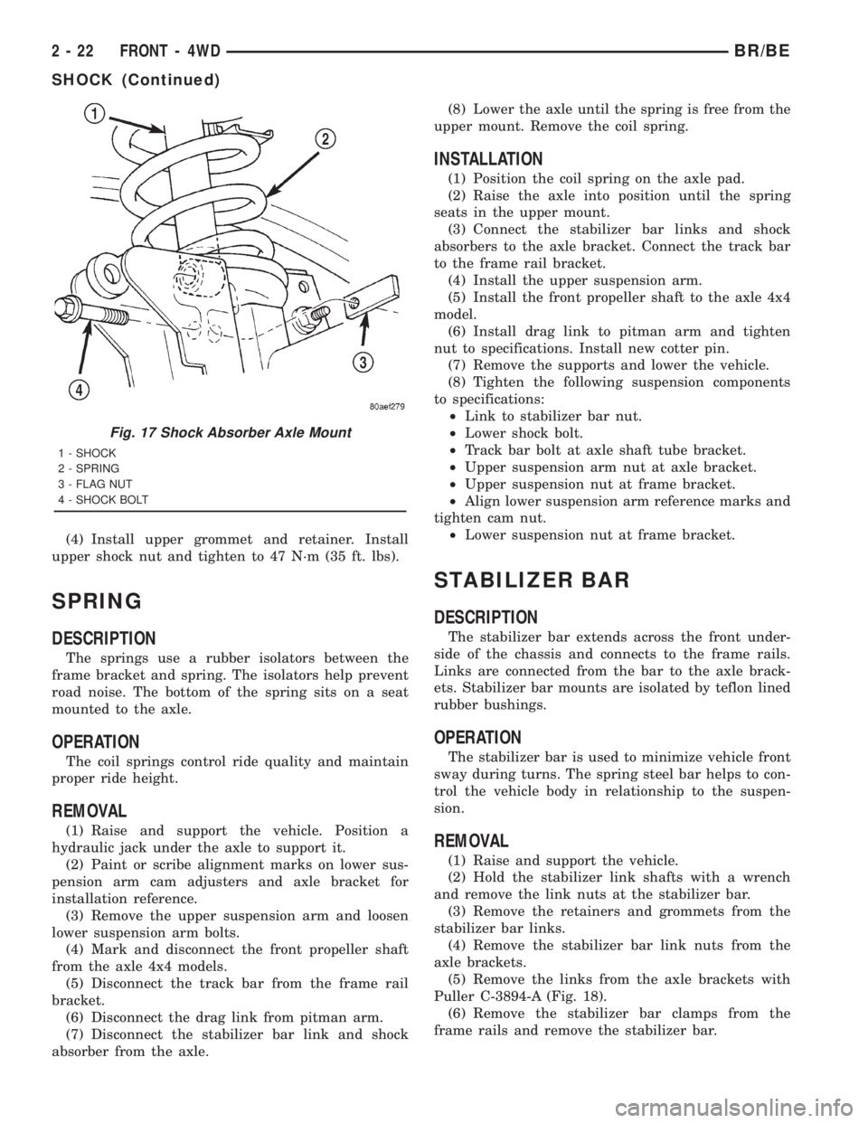
Fig. 17 Shock Absorber Axle Mount
1 - SHOCK
2 - SPRING
3 - FLAG NUT
4 - SHOCK BOLT
2 - 22 FRONT - 4WDBR/BE
SHOCK (Continued)
Page 425 of 2889
Refer to Electrical, Restraints for more information
on the clockspring. Refer to Electrical, Body Control/
Central Control Module for more information on the
Central Timer Module. Refer to the appropriate wir-
ing information. The wiring information includes wir-
ing diagrams, proper wire and connector repair
procedures, details of wire harness routing and
retention, connector pin-out information and location
views for the various wire harness connectors, splices
and grounds. Following are general descriptions of
the remaining major components in the standard and
optional factory-installed audio systems.
OPERATION
See the owner's manual in the vehicle glove box for
more information on the features, use and operation
of each of the available audio systems.
CENTRAL TIMER MODULE
The high-line or premium Central Timer Module
(CTM) can also control some features of the audio
system when the vehicle is equipped with the
optional RAZ radio receiver and remote radio
switches. A high-line CTM is used on high-line ver-
sions of this vehicle. A premium CTM is used on
vehicles equipped with the optional heated seats. The
CTM combines the functions of a chime/buzzer mod-
ule, an intermittent wipe module, an illuminated
entry module, a remote keyless entry module, and a
vehicle theft security system module in a single unit.
The high-line or premium CTM also controls and
integrates many of the additional electronic functions
and features included on models with this option.The RAZ radio receiver with a remote radio switch
option is one of the features that the CTM controls.
The CTM is programmed to send switch status mes-
sages over the Chrysler Collision Detection (CCD)
data bus to control the volume, seek, and pre-set sta-
tion advance functions of the RAZ radio receiver. The
CTM monitors the status of the remote radio
switches located on the steering wheel through a
hard wired circuit. The CTM then sends the proper
switch status messages to the radio receiver. The
electronic circuitry within the radio receiver responds
to the switch status messages it receives by adjusting
the radio settings as requested.
Refer to Electrical, Body Control/Central Timer
Module for more information on the high-line CTM.
Refer to Remote Radio Switch in Description and
Operation for more information on this component.
In addition, radio receivers connected to the CCD
data bus have several audio system functions that
can be diagnosed using a DRBIIItscan tool. Refer to
the proper Diagnostic Procedures manual for more
information on DRBIIIttesting of the audio systems.
DIAGNOSIS AND TESTING - AUDIO
WARNING: ON VEHICLES EQUIPPED WITH AIR-
BAGS, REFER TO ELECTRICAL, RESTRAINTS
BEFORE ATTEMPTING ANY STEERING WHEEL,
STEERING COLUMN, OR INSTRUMENT PANEL
COMPONENT DIAGNOSIS OR SERVICE. FAILURE
TO TAKE THE PROPER PRECAUTIONS COULD
RESULT IN ACCIDENTAL AIRBAG DEPLOYMENT
AND POSSIBLE PERSONAL INJURY.
8A - 2 AUDIOBR/BE
AUDIO (Continued)
Page 453 of 2889
external connector receptacles that connect it to the
vehicle electrical system through one (base) or two
(high-line/premium) take outs with connectors from
the instrument panel wire harness.
The base version of the CTM is used on base mod-
els of this vehicle. It is also sometimes referred to as
the Integrated Electronic Module (IEM). The base
version of the CTM combines the functions of a
chime module and an intermittent wipe module in a
single unit. The high-line version of the CTM is used
on high-line vehicles. The high-line CTM provides all
of the functions of the base version of the CTM, but
also is used to control and integrate many additional
electronic functions and features included on high-
line models. The premium version of the CTM is the
same as the high-line version, but is used only on
models equipped with the heated seat option.
The high-line and premium versions of the CTM
utilize integrated circuitry and information carried
on the Chrysler Collision Detection (CCD) data bus
network along with many hard wired inputs to mon-
itor many sensor and switch inputs throughout the
vehicle. In response to those inputs, the internal cir-
cuitry and programming of the CTM allow it to con-
trol and integrate many electronic functions and
features of the vehicle through both hard wired out-
puts and the transmission of electronic message out-
puts to other electronic modules in the vehicle over
the CCD data bus.
The features that the CTM supports or controls
include the following:
²Automatic Door Lock- The high-line/premium
CTM provides an optional automatic door lock fea-
ture (also known as rolling door locks). This is a pro-
grammable feature.
²Central Locking- The high-line/premium CTM
provides an optional central locking/unlocking fea-
ture.
²Chimes- All versions of the CTM provide chime
service through an integral chime tone generator.
²Courtesy Lamps- The high-line/premium CTM
provides courtesy lamp control with timed load shed-
ding.
²Door Lock Inhibit- The high-line/premium
CTM provides a door lock inhibit feature.
²Enhanced Accident Response- The high-line/
premium CTM provides an optional enhanced acci-
dent response feature. This is a programmable
feature.
²Heated Seats- The premium CTM controls the
optional heated seat system by controlling the opera-
tion of the heated seat relay.
²Illuminated Entry- The high-line/premium
CTM provides a timed illuminated entry feature.²Intermittent Wipe Control- All versions of
the CTM provide control of the intermittent wipe
delay, and wipe-after-wash features.
²Panic Mode- The high-line/premium CTM pro-
vides support for the optional RKE system panic
mode features.
²Power Lock Control- The high-line/premium
CTM provides the optional power lock system fea-
tures, including support for the automatic door lock
and door lock inhibit modes.
²Programmable Features- The high-line/pre-
mium CTM provides support for certain programma-
ble features.
²Remote Keyless Entry- The high-line/pre-
mium CTM provides the optional Remote Keyless
Entry (RKE) system features, including support for
the RKE Lock (with optional horn chirp), Unlock,
Panic, and illuminated entry modes, as well as the
ability to be programmed to recognize up to four
RKE transmitters. The RKE horn chirp is a program-
mable feature.
²Remote Radio Switch Interface- The high-
line/premium CTM monitors and transmits the sta-
tus of the optional remote radio switches.
²Speed Sensitive Intermittent Wipe Control-
The high-line/premium CTM provides the speed sen-
sitive intermittent wipe feature.
²Vehicle Theft Alarm- The high-line/premium
CTM provides control of the optional Vehicle Theft
Alarm features, including support for the central
locking/unlocking mode.
Hard wired circuitry connects the CTM to the elec-
trical system of the vehicle. These hard wired circuits
are integral to several wire harnesses, which are
routed throughout the vehicle and retained by many
different methods. These circuits may be connected to
each other, to the vehicle electrical system and to the
CTM through the use of a combination of soldered
splices, splice block connectors, and many different
types of wire harness terminal connectors and insu-
lators. Refer to the appropriate wiring information.
The wiring information includes wiring diagrams,
proper wire and connector repair procedures, further
details on wire harness routing and retention, as well
as pin-out and location views for the various wire
harness connectors, splices and grounds.
All versions of the CTM for this model are serviced
only as a complete unit. Many of the electronic fea-
tures in the vehicle controlled or supported by the
high-line or premium versions of the CTM are pro-
grammable using the DRBIIItscan tool. In addition,
the high-line/premium CTM software is Flash com-
patible, which means it can be reprogrammed using
Flash reprogramming procedures. However, if any of
the CTM hardware components are damaged or
faulty, the entire CTM unit must be replaced. The
8E - 2 ELECTRONIC CONTROL MODULESBR/BE
BODY CONTROL/CENTRAL TIMER MODULE (Continued)
Page 516 of 2889
HEATED SYSTEMS
TABLE OF CONTENTS
page page
HEATED MIRRORS......................... 1 HEATED SEATSYSTEM..................... 5
HEATED MIRRORS
TABLE OF CONTENTS
page page
HEATED MIRRORS
DESCRIPTION............................1
OPERATION.............................2
DIAGNOSIS AND TESTING..................2
HEATED MIRROR SYSTEM................2
MIRROR SWITCH
DESCRIPTION............................3
OPERATION.............................3DIAGNOSIS AND TESTING..................3
HEATED MIRROR SWITCH................3
HEATED MIRROR GRID
DESCRIPTION............................4
OPERATION.............................4
DIAGNOSIS AND TESTING..................0
HEATED MIRROR GRID...................4
HEATED MIRRORS
DESCRIPTION - HEATED MIRROR SYSTEM
Electrically heated outside rear view mirrors are
an additional factory-installed option on models that
are equipped with factory-installed dual power mir-
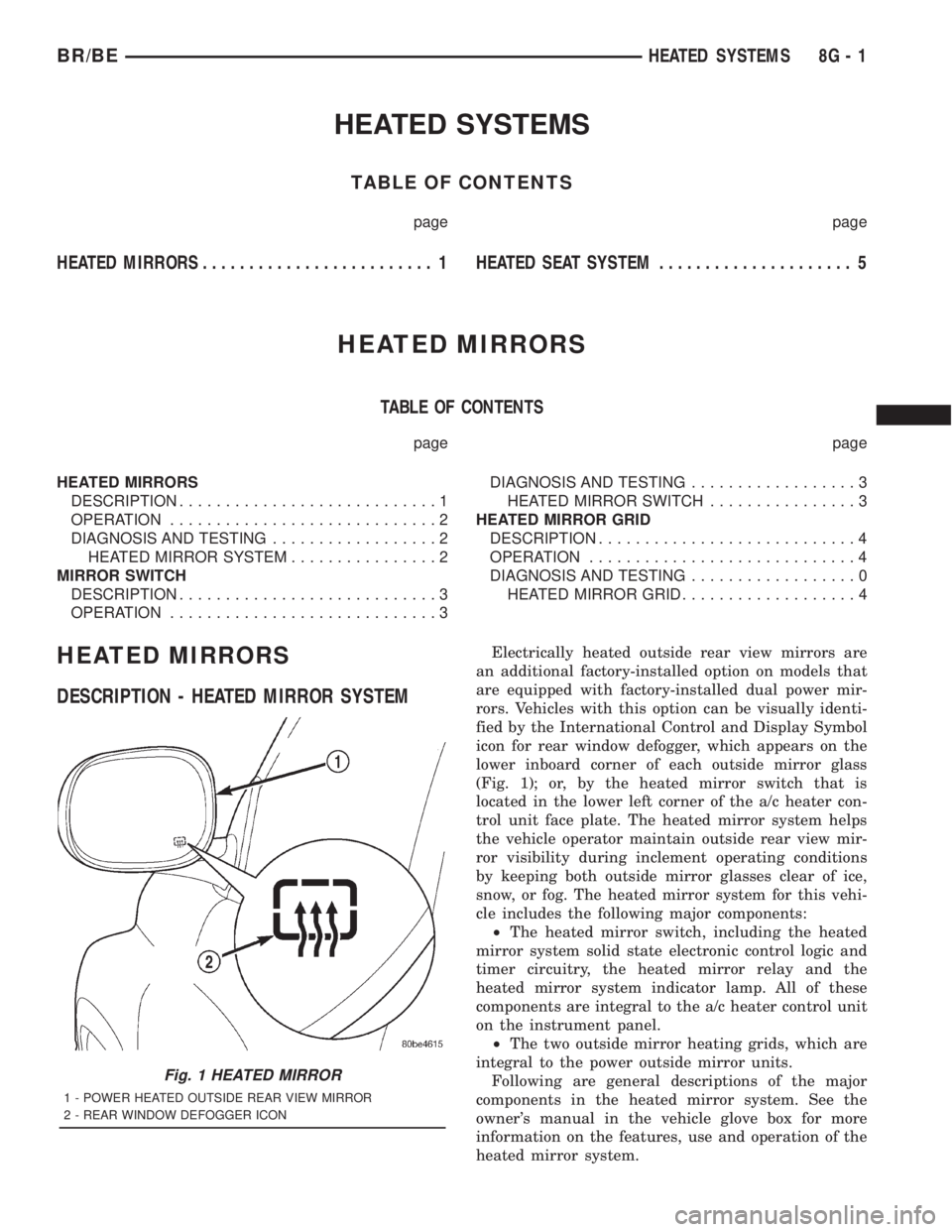
rors. Vehicles with this option can be visually identi-
fied by the International Control and Display Symbol
icon for rear window defogger, which appears on the
lower inboard corner of each outside mirror glass
(Fig. 1); or, by the heated mirror switch that is
located in the lower left corner of the a/c heater con-
trol unit face plate. The heated mirror system helps
the vehicle operator maintain outside rear view mir-
ror visibility during inclement operating conditions
by keeping both outside mirror glasses clear of ice,
snow, or fog. The heated mirror system for this vehi-
cle includes the following major components:
²The heated mirror switch, including the heated
mirror system solid state electronic control logic and
timer circuitry, the heated mirror relay and the
heated mirror system indicator lamp. All of these
components are integral to the a/c heater control unit
on the instrument panel.
²The two outside mirror heating grids, which are
integral to the power outside mirror units.
Following are general descriptions of the major
components in the heated mirror system. See the
owner's manual in the vehicle glove box for more
information on the features, use and operation of the
heated mirror system.
Fig. 1 HEATED MIRROR
1 - POWER HEATED OUTSIDE REAR VIEW MIRROR
2 - REAR WINDOW DEFOGGER ICON
BR/BEHEATED SYSTEMS 8G - 1
Page 520 of 2889
HEATED SEAT SYSTEM
TABLE OF CONTENTS
page page
HEATED SEAT SYSTEM
DESCRIPTION............................5
OPERATION.............................6
DIAGNOSIS AND TESTING..................6
HEATED SEAT SYSTEM..................6
DRIVER SEAT HEATER SWITCH
DESCRIPTION............................7
OPERATION.............................7
DIAGNOSIS AND TESTING..................8
HEATED SEAT SWITCH...................8
REMOVAL...............................9
INSTALLATION............................9
HEATED SEAT ELEMENT
DESCRIPTION...........................10
OPERATION.............................10
DIAGNOSIS AND TESTING.................11HEATED SEAT ELEMENT & SENSOR.......11
HEATED SEAT RELAY
DESCRIPTION...........................11
OPERATION.............................12
DIAGNOSIS AND TESTING.................12
HEATED SEAT RELAY...................12
REMOVAL..............................13
INSTALLATION...........................13
PASSENGER SEAT HEATER SWITCH
DESCRIPTION...........................13
OPERATION.............................14
DIAGNOSIS AND TESTING.................14
HEATED SEAT SWITCH..................14
REMOVAL..............................15
INSTALLATION...........................16
HEATED SEAT SYSTEM
DESCRIPTION
Individually controlled electrically heated front
seats are available factory-installed optional equip-
ment on the Ram quad cab models that are also
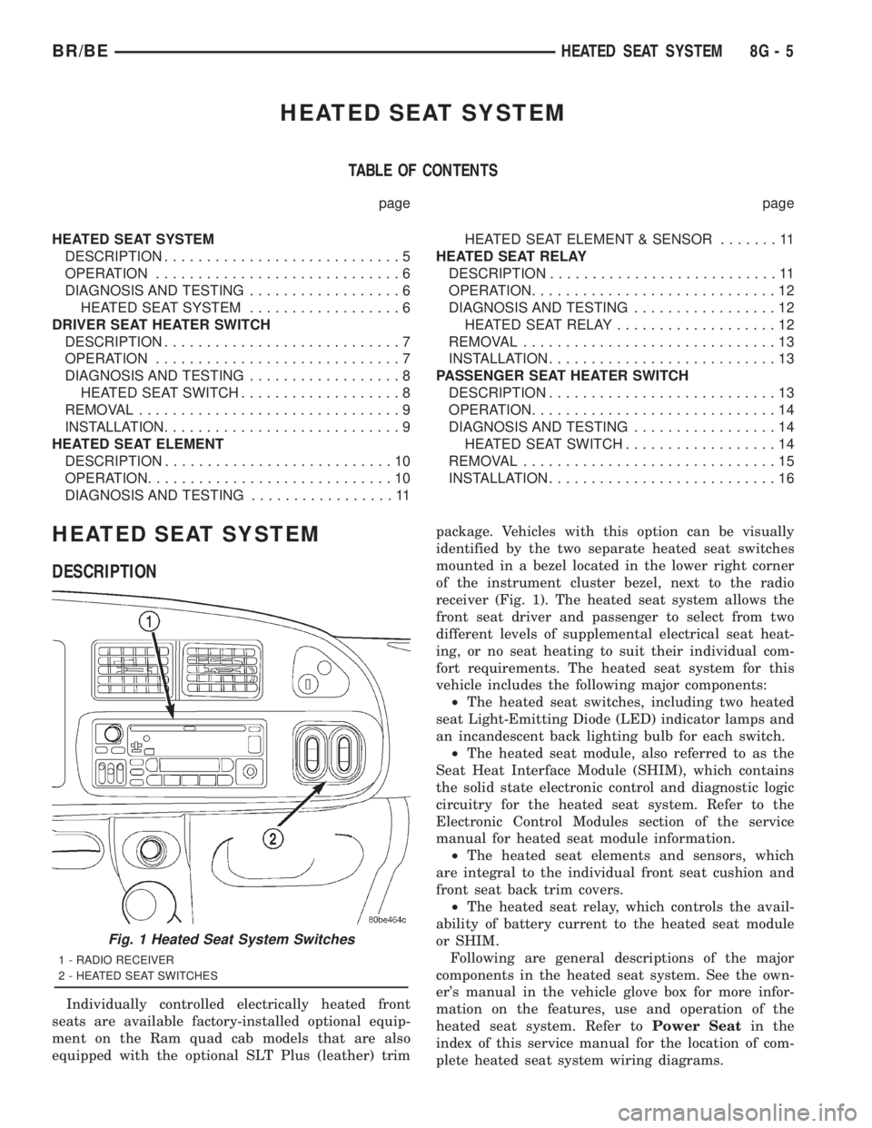
equipped with the optional SLT Plus (leather) trimpackage. Vehicles with this option can be visually
identified by the two separate heated seat switches
mounted in a bezel located in the lower right corner
of the instrument cluster bezel, next to the radio
receiver (Fig. 1). The heated seat system allows the
front seat driver and passenger to select from two
different levels of supplemental electrical seat heat-
ing, or no seat heating to suit their individual com-
fort requirements. The heated seat system for this
vehicle includes the following major components:
²The heated seat switches, including two heated
seat Light-Emitting Diode (LED) indicator lamps and
an incandescent back lighting bulb for each switch.
²The heated seat module, also referred to as the
Seat Heat Interface Module (SHIM), which contains
the solid state electronic control and diagnostic logic
circuitry for the heated seat system. Refer to the
Electronic Control Modules section of the service
manual for heated seat module information.
²The heated seat elements and sensors, which
are integral to the individual front seat cushion and
front seat back trim covers.
²The heated seat relay, which controls the avail-
ability of battery current to the heated seat module
or SHIM.
Following are general descriptions of the major
components in the heated seat system. See the own-
er's manual in the vehicle glove box for more infor-
mation on the features, use and operation of the
heated seat system. Refer toPower Seatin the
index of this service manual for the location of com-
plete heated seat system wiring diagrams.
Fig. 1 Heated Seat System Switches
1 - RADIO RECEIVER
2 - HEATED SEAT SWITCHES
BR/BEHEATED SEAT SYSTEM 8G - 5
Page 521 of 2889
OPERATION
The heated seat module receives fused battery cur-
rent through the energized heated seat relay in the
Junction Block (JB) only when the engine is running.
The heated seat switches receive battery current
through a fused ignition switch output (run) circuit
only when the ignition switch is in the On position.
The heated seat module shares a common ground cir-
cuit with each of the heated seat elements. The
heated seat elements will only operate when the sur-
face temperature of the seat cushion cover at the
heated seat sensors is below the designed tempera-
ture set points of the system.
The heated seat module will automatically turn off
the heated seat elements if it detects a short in the
heated seat element circuit or a heated seat sensor
value that is out of range. The heated seat system
will also be turned off automatically whenever the
ignition switch is turned to any position except On or
if the engine quits running. If the ignition switch is
turned to the Off position or if the engine quits run-
ning while a heated seat is turned ON, the heated
seat will remain Off after the engine is restarted
until a heated seat switch is depressed again.
The heated seat module monitors inputs from the
heated seat sensors and the heated seat switches. In
response to these inputs the heated seat module uses
its internal programming to control outputs to the
heated seat elements in both front seats and to con-
trol the heated seat LED indicator lamps located in
both of the heated seat switches. The heated seat
module is also programmed to provide a self-diagnos-
tic capability. When the module detects certain fail-
ures within the heated seat system, it will provide a
visual indication of the failure by flashing the indica-
tor lamps in the heated seat switches.
DIAGNOSIS & TESTING - HEATED SEAT
SYSTEM
SELF-DIAGNOSIS
The heated seat system is capable of performing
some self-diagnostics. The following table depicts the
various failure modes which will be reported to the
vehicle operator or technician by flashing the individ-
ual heated seat switch Light Emitting Diode (LED)
indicator lamps. See the Heated Seat System Self-Di-
agnosis table for the diagnostic routines. The driver
side heated seat switch indicator lamps will flash if a
failure occurs in the driver side heated seat, and the
passenger side heated seat switch indicator lamps
will flash for a passenger side heated seat failure. If
a monitored heated seat system failure occurs, the
switch indicator lamps will flash at a pulse rate of
about one-half second on, followed by about one-half
second off for a duration of about one minute afterthe switch for the faulty heated seat is depressed in
either the Low or High direction. This process will
repeat every time the faulty heated seat switch is
actuated until the problem has been corrected.
Heated Seat System Self-Diagnosis
Monitored FailureSwitch High
Indicator LampSwitch Low
Indicator Lamp
Heated Seat
Element ShortedFlashing Flashing
Heated Seat
Element OpenFlashing Off
Heated Seat
Sensor Value Out
of RangeOff Flashing
TESTING
Refer toPower Seatin the index of this service
manual for the location of complete heated seat sys-
tem wiring diagrams. Before testing the individual
components in the heated seat system, perform the
following preliminary checks:
WARNING: ON VEHICLES EQUIPPED WITH AIR-
BAGS, DISABLE THE AIRBAG SYSTEM BEFORE
ATTEMPTING ANY STEERING WHEEL, STEERING
COLUMN, OR INSTRUMENT PANEL COMPONENT
DIAGNOSIS OR SERVICE. DISCONNECT AND ISO-
LATE THE BATTERY NEGATIVE (GROUND) CABLE,
THEN WAIT TWO MINUTES FOR THE AIRBAG SYS-
TEM CAPACITOR TO DISCHARGE BEFORE PER-
FORMING FURTHER DIAGNOSIS OR SERVICE. THIS
IS THE ONLY SURE WAY TO DISABLE THE AIRBAG
SYSTEM. FAILURE TO TAKE THE PROPER PRE-
CAUTIONS COULD RESULT IN ACCIDENTAL AIR-
BAG DEPLOYMENT AND POSSIBLE PERSONAL
INJURY.
²If the heated seat switch back lighting and the
cluster illumination lamps do not illuminate with the
headlamps or park lamps turned On, refer toInstru-
ment Clusterin the index of this service manual for
the location of the proper cluster illumination lamps
diagnosis and testing procedures. If the heated seat
switch back lighting does not illuminate, but the
cluster illumination lamps do illuminate with the
headlamps or park lamps turned On, refer to
Heated Seat Switchin this section for the location
of the proper heated seat switch diagnosis and test-
ing procedure.
²If a single indicator lamp for one heated seat
switch does not operate and the heated seat elements
do heat, refer toHeated Seat Switchin this section
for the location of the proper heated seat switch diag-
nosis and testing procedure.
8G - 6 HEATED SEAT SYSTEMBR/BE
HEATED SEAT SYSTEM (Continued)
Page 522 of 2889
²If both indicator lamps for a heated seat switch
operate, but the heated seat elements do not heat,
refer toHeated Seat Modulein Electronic Control
Modules for the location of the proper heated seat
module diagnosis and testing procedures. Also refer
to the Body Diagnostic Manual for additional diagno-
sis and testing procedures.
²If none of the indicator lamps for both heated
seat switches will operate and the heated seat ele-
ments for both seats do not heat, refer toHeated
Seat Relayin this section for the location of the
proper heated seat relay diagnosis and testing proce-
dures.
²If the an indicator lamp on either heated seat
switch remains illuminated after the heated seat has
been turned Off, refer toHeated Seat Modulein
Electronic Control Modules for the location of the
proper heated seat module diagnosis and testing pro-
cedures. Also refer to the Body Diagnostic Manual for
additional diagnosis and testing procedures.
DRIVER SEAT HEATER
SWITCH
DESCRIPTION
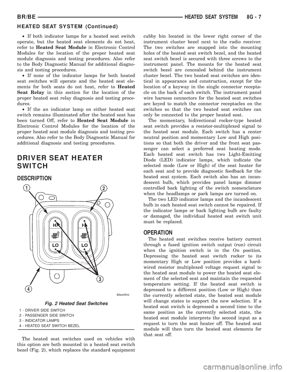
The heated seat switches used on vehicles with
this option are both mounted in a heated seat switch
bezel (Fig. 2), which replaces the standard equipmentcubby bin located in the lower right corner of the
instrument cluster bezel next to the radio receiver.
The two switches are snapped into the mounting
holes of the heated seat switch bezel, and the heated
seat switch bezel is secured with three screws to the
instrument panel. The mounts for the heated seat
switch bezel are concealed behind the instrument
cluster bezel. The two heated seat switches are iden-
tical in appearance and construction, except for the
location of a keyway in the single connector recepta-
cle on the back of each switch. The instrument panel
wire harness connectors for the heated seat switches
are keyed to match the connector receptacles on the
switches so that the two heated seat switches can
only be connected to the proper heated seat.
The momentary, bidirectional rocker-type heated
seat switch provides a resistor-multiplexed signal to
the heated seat module. Each switch has a center
neutral position and momentary Low and High posi-
tions so that both the driver and the front seat pas-
senger can select a preferred seat heating mode.
Each heated seat switch has two Light-Emitting
Diode (LED) indicator lamps, which indicate the
selected mode (Low or High) of the seat heater for
each seat and to provide diagnostic feedback for the
heated seat system. Each switch also has an incan-
descent bulb, which provides panel lamps dimmer
controlled back lighting of the switch nomenclature
when the headlamps or park lamps are turned on.
The two LED indicator lamps and the incandescent
bulb in each heated seat switch cannot be repaired. If
the indicator lamps or back lighting bulb are faulty
or damaged, the individual heated seat switch unit
must be replaced.
OPERATION
The heated seat switches receive battery current
through a fused ignition switch output (run) circuit
when the ignition switch is in the On position.
Depressing the heated seat switch rocker to its
momentary High or Low position provides a hard-
wired resistor multiplexed voltage request signal to
the heated seat module to power the heated seat ele-
ment of the selected seat and maintain the requested
temperature setting. If the heated seat switch is
depressed to a different position (Low or High) than
the currently selected state, the heated seat module
will change states to support the new selection. If a
heated seat switch is depressed a second time to the
same position as the currently selected state, the
heated seat module interprets the second input as a
request to turn the seat heater off. The heated seat
module will then turn the heated seat elements for
that seat off.
Fig. 2 Heated Seat Switches
1 - DRIVER SIDE SWITCH
2 - PASSENGER SIDE SWITCH
3 - INDICATOR LAMPS
4 - HEATED SEAT SWITCH BEZEL
BR/BEHEATED SEAT SYSTEM 8G - 7
HEATED SEAT SYSTEM (Continued)
Page 525 of 2889
(3) Reconnect the two instrument panel wire har-
ness connectors to the connector receptacles on the
backs of the heated seat switches.
(4) Position the heated seat switch bezel and both
switches in the instrument panel mounting hole as a
unit.
(5) Install and tighten the three screws that secure
the heated seat switch bezel to the instrument panel.
Tighten the screws to 2.2 N´m (20 in. lbs.).
(6) Install the cluster bezel onto the instrument
panel. Refer toCluster Bezelin the index of this
service manual for the location of the proper cluster
bezel installation procedures.
(7) Reconnect the battery negative cable.
HEATED SEAT ELEMENT
DESCRIPTION
Vehicles equipped with the optional heated seat
system have two sets of electrically operated heating
element grids located in each outboard seating posi-
tion of the front seat, one set for the seat cushion
and the other set for the seat back. Each of the
heated seat element grids consists of a single length
of resistor wire that is routed in a zigzag pattern and
captured between the leather trim cover and the
foam rubber backing on the underside of its respec-
tive seat cushion trim cover and seat back trim cover
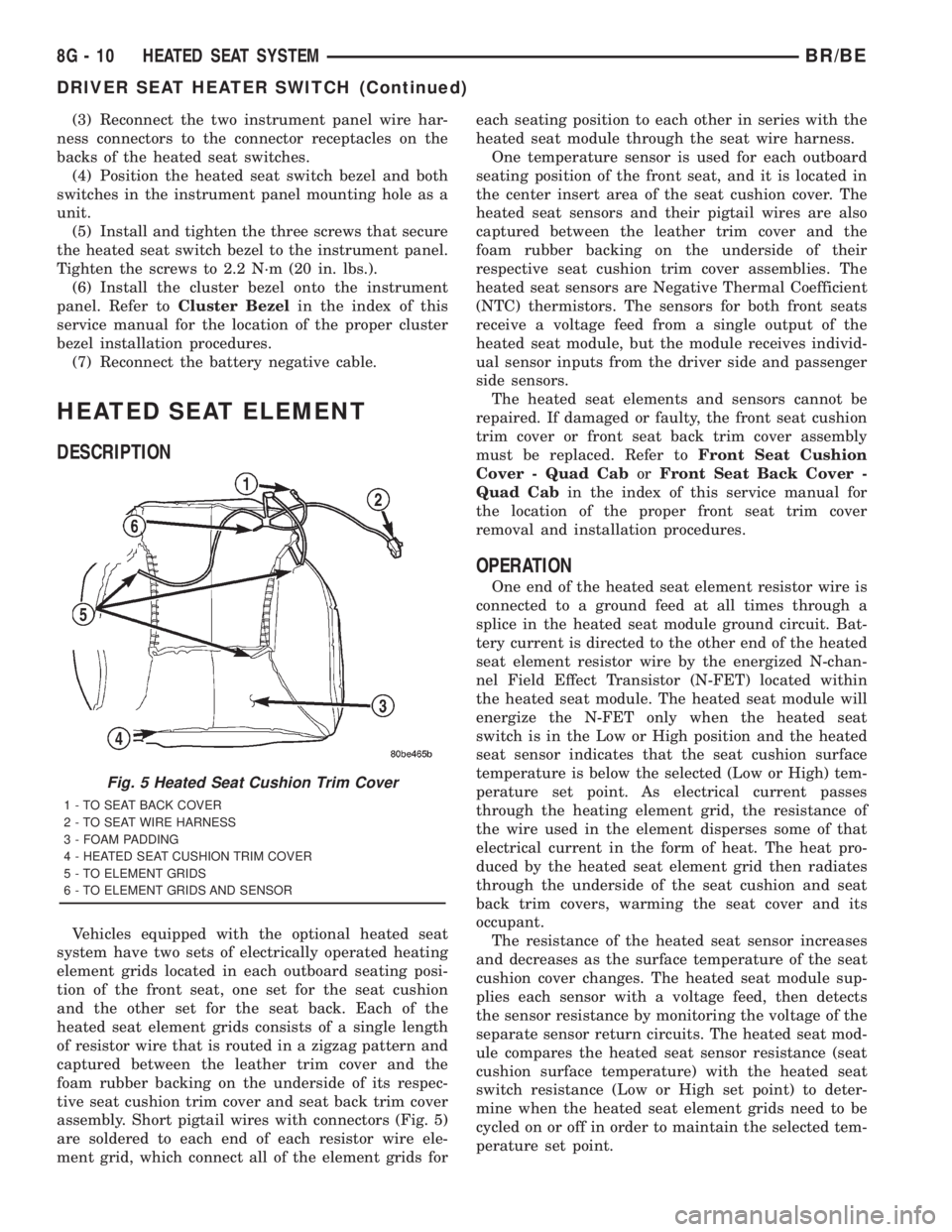
assembly. Short pigtail wires with connectors (Fig. 5)
are soldered to each end of each resistor wire ele-
ment grid, which connect all of the element grids foreach seating position to each other in series with the
heated seat module through the seat wire harness.
One temperature sensor is used for each outboard
seating position of the front seat, and it is located in
the center insert area of the seat cushion cover. The
heated seat sensors and their pigtail wires are also
captured between the leather trim cover and the
foam rubber backing on the underside of their
respective seat cushion trim cover assemblies. The
heated seat sensors are Negative Thermal Coefficient
(NTC) thermistors. The sensors for both front seats
receive a voltage feed from a single output of the
heated seat module, but the module receives individ-
ual sensor inputs from the driver side and passenger
side sensors.
The heated seat elements and sensors cannot be
repaired. If damaged or faulty, the front seat cushion
trim cover or front seat back trim cover assembly
must be replaced. Refer toFront Seat Cushion
Cover - Quad CaborFront Seat Back Cover -
Quad Cabin the index of this service manual for
the location of the proper front seat trim cover
removal and installation procedures.
OPERATION
One end of the heated seat element resistor wire is
connected to a ground feed at all times through a
splice in the heated seat module ground circuit. Bat-
tery current is directed to the other end of the heated
seat element resistor wire by the energized N-chan-
nel Field Effect Transistor (N-FET) located within
the heated seat module. The heated seat module will
energize the N-FET only when the heated seat
switch is in the Low or High position and the heated
seat sensor indicates that the seat cushion surface
temperature is below the selected (Low or High) tem-
perature set point. As electrical current passes
through the heating element grid, the resistance of
the wire used in the element disperses some of that
electrical current in the form of heat. The heat pro-
duced by the heated seat element grid then radiates
through the underside of the seat cushion and seat
back trim covers, warming the seat cover and its
occupant.
The resistance of the heated seat sensor increases
and decreases as the surface temperature of the seat
cushion cover changes. The heated seat module sup-
plies each sensor with a voltage feed, then detects
the sensor resistance by monitoring the voltage of the
separate sensor return circuits. The heated seat mod-
ule compares the heated seat sensor resistance (seat
cushion surface temperature) with the heated seat
switch resistance (Low or High set point) to deter-
mine when the heated seat element grids need to be
cycled on or off in order to maintain the selected tem-
perature set point.
Fig. 5 Heated Seat Cushion Trim Cover
1 - TO SEAT BACK COVER
2 - TO SEAT WIRE HARNESS
3 - FOAM PADDING
4 - HEATED SEAT CUSHION TRIM COVER
5 - TO ELEMENT GRIDS
6 - TO ELEMENT GRIDS AND SENSOR
8G - 10 HEATED SEAT SYSTEMBR/BE
DRIVER SEAT HEATER SWITCH (Continued)
Page 532 of 2889
HORN
TABLE OF CONTENTS
page page
HORN
DESCRIPTION............................1
OPERATION.............................1
HORN
DESCRIPTION............................2
OPERATION.............................2
DIAGNOSIS AND TESTING..................2
HORN................................2
REMOVAL...............................2
INSTALLATION............................3
HORN RELAY
DESCRIPTION............................3OPERATION.............................3
DIAGNOSIS AND TESTING..................3
HORN RELAY..........................3
REMOVAL...............................4
INSTALLATION............................4
HORN SWITCH
DESCRIPTION............................4
OPERATION.............................5
DIAGNOSIS AND TESTING..................5
HORN SWITCH.........................5
REMOVAL...............................5
HORN
DESCRIPTION
An electric horn system is standard factory-in-
stalled equipment on this model. Two horn systems
are offered on this model. The standard equipment
horn system features a single low-note electromag-
netic horn unit, while the optional dual horn system
features one low-note horn unit and one high-note
horn unit. Both horn systems use a non-switched
source of battery current so that the system will
remain functional, regardless of the ignition switch
position. The horn system includes the following com-
ponents:
²Clockspring
²High-line or premium Central Timer Module
(CTM)
²Horn(s)
²Horn relay
²Horn switch
(Refer to 8 - ELECTRICAL/RESTRAINTS/CLOCK-
SPRING - DESCRIPTION) for more information on
this component. (Refer to 8 - ELECTRICAL/ELEC-
TRONIC CONTROL MODULES/BODY CONTROL/
CENTRAL TIMER MODUL - DESCRIPTION) for
more information on this component. Refer to the
appropriate wiring information. The wiring informa-
tion includes wiring diagrams, proper wire and con-
nector repair procedures, details of wire harness
routing and retention, connector pin-out information
and location views for the various wire harness con-
nectors, splices and grounds. Following are general
descriptions of the remaining major components in
the horn system.
OPERATION
Each horn system is activated by a horn switch
concealed beneath the driver side airbag module trim
cover in the center of the steering wheel. Depressing
the center of the driver side airbag module trim cover
closes the horn switch. Closing the horn switch acti-
vates the horn relay. The activated horn relay then
switches the battery current needed to energize the
horn(s).
Refer to the owner's manual in the vehicle glove
box for more information on the features, use and
operation of the horn system.
CENTRAL TIMER MODULE
The high-line or premium Central Timer Module
(CTM) can also operate the horn system. A high-line
CTM is used on high-line versions of this vehicle. A
premium CTM is used on vehicles equipped with the
optional heated seats. The CTM combines the func-
tions of a chime/buzzer module, an intermittent wipe
module, an illuminated entry module, a remote key-
less entry module, and a vehicle theft security sys-
tem module in a single unit.
The high-line or premium CTM also controls and
integrates many of the additional electronic functions
and features included on models with this option.
The horn relay is one of the hard wired outputs of
the CTM. The high-line or premium CTM is pro-
grammed to energize or de-energize the horn relay in
response to certain inputs from the Vehicle Theft
Security System (VTSS) and/or the Remote Keyless
Entry (RKE) system.
(Refer to 8 - ELECTRICAL/ELECTRONIC CON-
TROL MODULES/BODY CONTROL/CENTRAL
TIMER MODUL - DESCRIPTION) for more informa-
BR/BEHORN 8H - 1