wiring DODGE RAM 2001 Service Repair Manual
[x] Cancel search | Manufacturer: DODGE, Model Year: 2001, Model line: RAM, Model: DODGE RAM 2001Pages: 2889, PDF Size: 68.07 MB
Page 1 of 2889
GROUP TAB LOCATOR
Introduction
0Lubrication & Maintenance
2Suspension
3Differential & Driveline
5Brakes
7Cooling
8AAudio
8BChime/Buzzer
8EElectronic Control Modules
8FEngine Systems
8GHeated Systems
8HHorn
8IIgnition Control
8JInstrument Cluster
8LLamps
8MMessage Systems
8NPower Systems
8ORestraints
8PSpeed Control
8QVehicle Theft Security
8RWipers/Washers
8WWiring
9Engine
11Exhaust System
13Frame & Bumpers
14Fuel System
19Steering
21Transmission/Transaxle
22Tires/Wheels
23Body
24Heating & Air Conditioning
25Emissions Control Systems
30New Vehicle Preparation
Component and System Index
Service Manual Comment Forms (Rear of Manual)
Page 106 of 2889
REMOVAL
(1) Disconnect the vacuum and wiring connector
from the shift housing.
(2) Remove indicator switch.
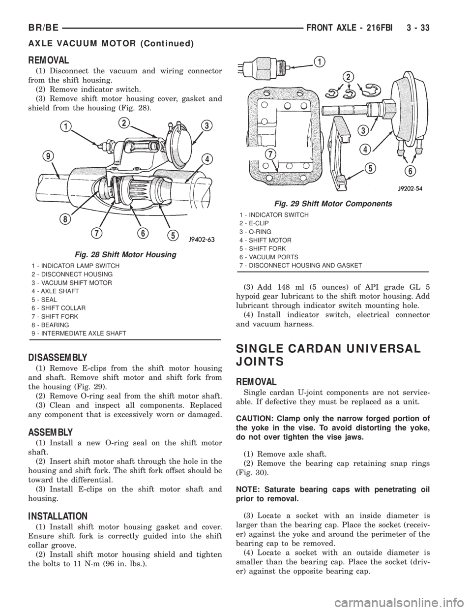
(3) Remove shift motor housing cover, gasket and
shield from the housing (Fig. 28).
DISASSEMBLY
(1) Remove E-clips from the shift motor housing
and shaft. Remove shift motor and shift fork from
the housing (Fig. 29).
(2) Remove O-ring seal from the shift motor shaft.
(3) Clean and inspect all components. Replaced
any component that is excessively worn or damaged.
ASSEMBLY
(1) Install a new O-ring seal on the shift motor
shaft.
(2) Insert shift motor shaft through the hole in the
housing and shift fork. The shift fork offset should be
toward the differential.
(3) Install E-clips on the shift motor shaft and
housing.
INSTALLATION
(1) Install shift motor housing gasket and cover.
Ensure shift fork is correctly guided into the shift
collar groove.
(2) Install shift motor housing shield and tighten
the bolts to 11 N´m (96 in. lbs.).(3) Add 148 ml (5 ounces) of API grade GL 5
hypoid gear lubricant to the shift motor housing. Add
lubricant through indicator switch mounting hole.
(4) Install indicator switch, electrical connector
and vacuum harness.
SINGLE CARDAN UNIVERSAL
JOINTS
REMOVAL
Single cardan U-joint components are not service-
able. If defective they must be replaced as a unit.
CAUTION: Clamp only the narrow forged portion of
the yoke in the vise. To avoid distorting the yoke,
do not over tighten the vise jaws.
(1) Remove axle shaft.
(2) Remove the bearing cap retaining snap rings
(Fig. 30).
NOTE: Saturate bearing caps with penetrating oil
prior to removal.
(3) Locate a socket with an inside diameter is
larger than the bearing cap. Place the socket (receiv-
er) against the yoke and around the perimeter of the
bearing cap to be removed.
(4) Locate a socket with an outside diameter is
smaller than the bearing cap. Place the socket (driv-
er) against the opposite bearing cap.
Fig. 28 Shift Motor Housing
1 - INDICATOR LAMP SWITCH
2 - DISCONNECT HOUSING
3 - VACUUM SHIFT MOTOR
4 - AXLE SHAFT
5 - SEAL
6 - SHIFT COLLAR
7 - SHIFT FORK
8 - BEARING
9 - INTERMEDIATE AXLE SHAFT
Fig. 29 Shift Motor Components
1 - INDICATOR SWITCH
2 - E-CLIP
3 - O-RING
4 - SHIFT MOTOR
5 - SHIFT FORK
6 - VACUUM PORTS
7 - DISCONNECT HOUSING AND GASKET
BR/BEFRONT AXLE - 216FBI 3 - 33
AXLE VACUUM MOTOR (Continued)
Page 138 of 2889
REMOVAL
(1) Disconnect the vacuum and wiring connector
from the shift housing.
(2) Remove indicator switch.
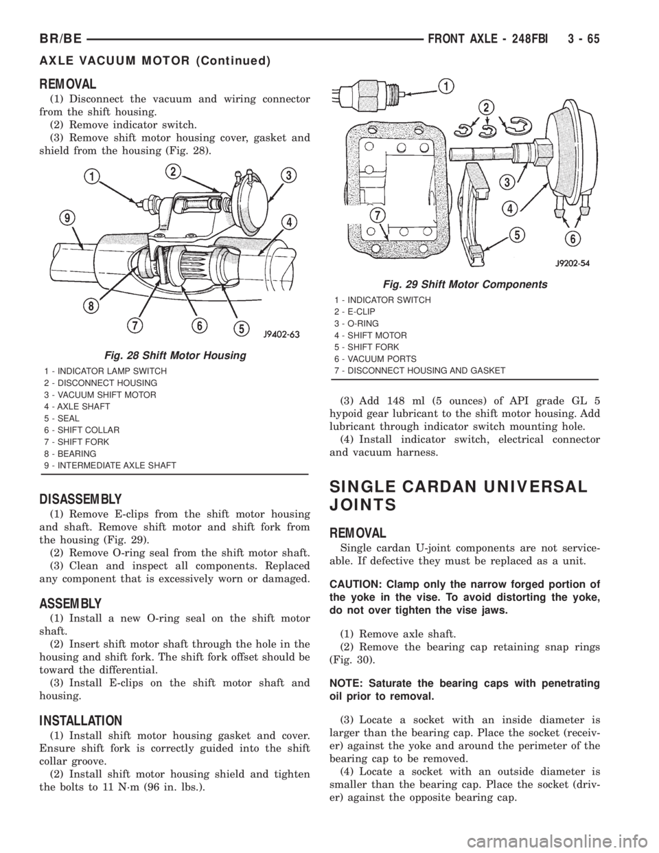
(3) Remove shift motor housing cover, gasket and
shield from the housing (Fig. 28).
DISASSEMBLY
(1) Remove E-clips from the shift motor housing
and shaft. Remove shift motor and shift fork from
the housing (Fig. 29).
(2) Remove O-ring seal from the shift motor shaft.
(3) Clean and inspect all components. Replaced
any component that is excessively worn or damaged.
ASSEMBLY
(1) Install a new O-ring seal on the shift motor
shaft.
(2) Insert shift motor shaft through the hole in the
housing and shift fork. The shift fork offset should be
toward the differential.
(3) Install E-clips on the shift motor shaft and
housing.
INSTALLATION
(1) Install shift motor housing gasket and cover.
Ensure shift fork is correctly guided into the shift
collar groove.
(2) Install shift motor housing shield and tighten
the bolts to 11 N´m (96 in. lbs.).(3) Add 148 ml (5 ounces) of API grade GL 5
hypoid gear lubricant to the shift motor housing. Add
lubricant through indicator switch mounting hole.
(4) Install indicator switch, electrical connector
and vacuum harness.
SINGLE CARDAN UNIVERSAL
JOINTS
REMOVAL
Single cardan U-joint components are not service-
able. If defective they must be replaced as a unit.
CAUTION: Clamp only the narrow forged portion of
the yoke in the vise. To avoid distorting the yoke,
do not over tighten the vise jaws.
(1) Remove axle shaft.
(2) Remove the bearing cap retaining snap rings
(Fig. 30).
NOTE: Saturate the bearing caps with penetrating
oil prior to removal.
(3) Locate a socket with an inside diameter is
larger than the bearing cap. Place the socket (receiv-
er) against the yoke and around the perimeter of the
bearing cap to be removed.
(4) Locate a socket with an outside diameter is
smaller than the bearing cap. Place the socket (driv-
er) against the opposite bearing cap.
Fig. 28 Shift Motor Housing
1 - INDICATOR LAMP SWITCH
2 - DISCONNECT HOUSING
3 - VACUUM SHIFT MOTOR
4 - AXLE SHAFT
5 - SEAL
6 - SHIFT COLLAR
7 - SHIFT FORK
8 - BEARING
9 - INTERMEDIATE AXLE SHAFT
Fig. 29 Shift Motor Components
1 - INDICATOR SWITCH
2 - E-CLIP
3 - O-RING
4 - SHIFT MOTOR
5 - SHIFT FORK
6 - VACUUM PORTS
7 - DISCONNECT HOUSING AND GASKET
BR/BEFRONT AXLE - 248FBI 3 - 65
AXLE VACUUM MOTOR (Continued)
Page 281 of 2889
(4) Have helper press and hold brake pedal to floor
and observe warning light.
(a) If warning light illuminates, switch is operat-
ing correctly.
(b) If light fails to illuminate, check circuit fuse,
bulb, and wiring. The parking brake switch can be
used to aid in identifying whether or not the brake
light bulb and fuse is functional. Repair or replace
parts as necessary and test differential pressure
switch operation again.
(5) If warning light still does not illuminate,
switch is faulty. Replace combination valve assembly,
bleed brake system and verify proper switch and
valve operation.
REMOVAL
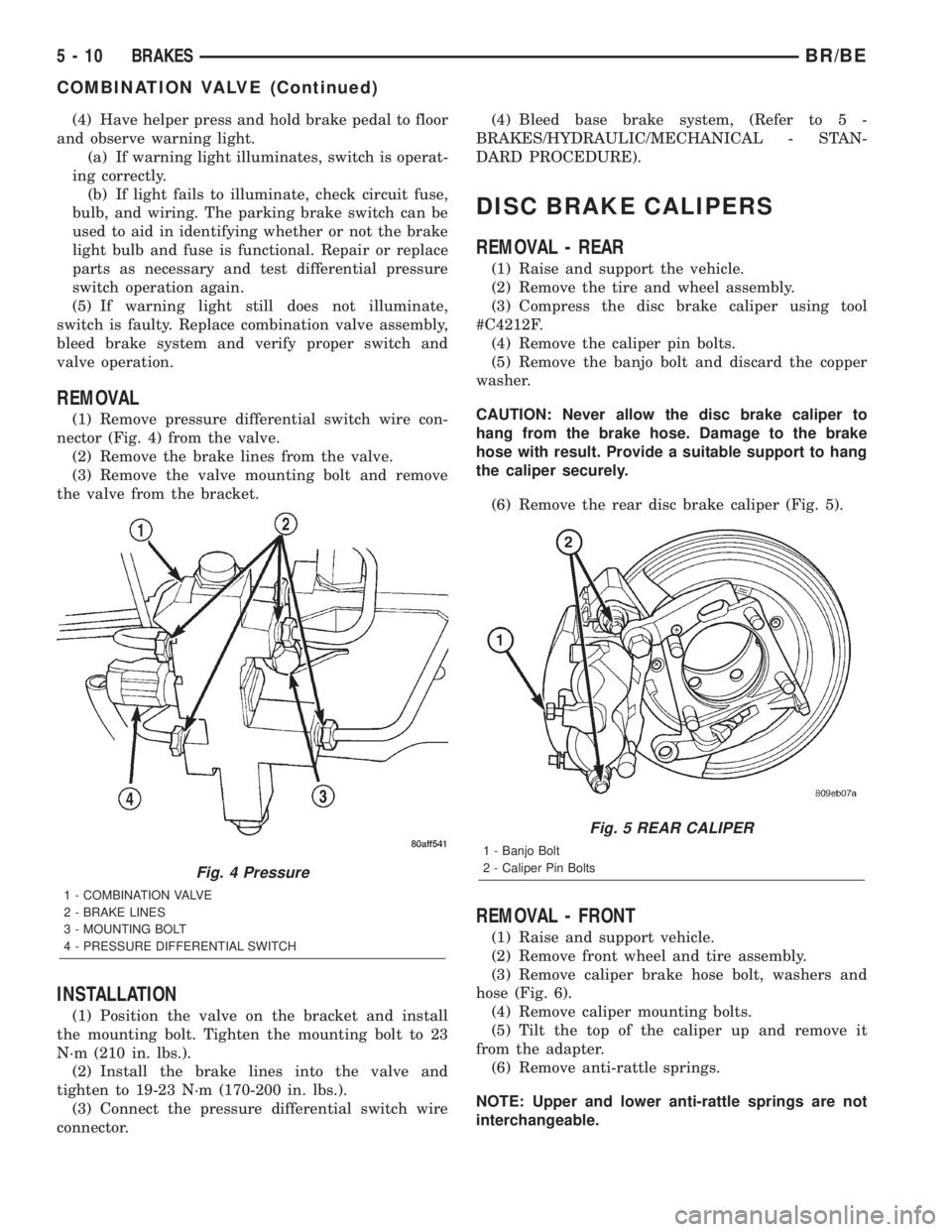
(1) Remove pressure differential switch wire con-
nector (Fig. 4) from the valve.
(2) Remove the brake lines from the valve.
(3) Remove the valve mounting bolt and remove
the valve from the bracket.
INSTALLATION
(1) Position the valve on the bracket and install
the mounting bolt. Tighten the mounting bolt to 23
N´m (210 in. lbs.).
(2) Install the brake lines into the valve and
tighten to 19-23 N´m (170-200 in. lbs.).
(3) Connect the pressure differential switch wire
connector.(4) Bleed base brake system, (Refer to 5 -
BRAKES/HYDRAULIC/MECHANICAL - STAN-
DARD PROCEDURE).
DISC BRAKE CALIPERS
REMOVAL - REAR
(1) Raise and support the vehicle.
(2) Remove the tire and wheel assembly.
(3) Compress the disc brake caliper using tool
#C4212F.
(4) Remove the caliper pin bolts.
(5) Remove the banjo bolt and discard the copper
washer.
CAUTION: Never allow the disc brake caliper to
hang from the brake hose. Damage to the brake
hose with result. Provide a suitable support to hang
the caliper securely.
(6) Remove the rear disc brake caliper (Fig. 5).
REMOVAL - FRONT
(1) Raise and support vehicle.
(2) Remove front wheel and tire assembly.
(3) Remove caliper brake hose bolt, washers and
hose (Fig. 6).
(4) Remove caliper mounting bolts.
(5) Tilt the top of the caliper up and remove it
from the adapter.
(6) Remove anti-rattle springs.
NOTE: Upper and lower anti-rattle springs are not
interchangeable.
Fig. 4 Pressure
1 - COMBINATION VALVE
2 - BRAKE LINES
3 - MOUNTING BOLT
4 - PRESSURE DIFFERENTIAL SWITCH
Fig. 5 REAR CALIPER
1 - Banjo Bolt
2 - Caliper Pin Bolts
5 - 10 BRAKESBR/BE
COMBINATION VALVE (Continued)
Page 334 of 2889
should not be disconnected. The individual compo-
nents that form the linkage assembly cannot be over-
hauled or serviced separately.
(1) Tighten cap on clutch fluid reservoir to avoid
spillage during installation.
(2) Position cylinders, connecting lines and reser-
voir in vehicle engine compartment. Locate the clutch
hydraulic line against the dash panel and behind all
engine hoses and wiring.
(3) Insert clutch master cylinder in dash panel.
Install and tighten the nuts to hold the clutch master
cylinder to the dash panel.
(4) Apply a light coating of grease to the inside
and outside diameter of the master cylinder bushing.
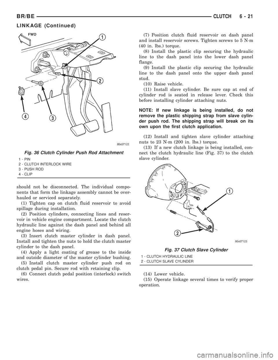
(5) Install clutch master cylinder push rod on
clutch pedal pin. Secure rod with retaining clip.
(6) Connect clutch pedal position (interlock) switch
wires.(7) Position clutch fluid reservoir on dash panel
and install reservoir screws. Tighten screws to 5 N´m
(40 in. lbs.) torque.
(8) Install the plastic clip securing the hydraulic
line to the dash panel into the lower dash panel
flange.
(9) Install the plastic clip securing the hydraulic
line to the dash panel onto the upper dash panel
stud.
(10) Raise vehicle.
(11) Install slave cylinder. Be sure cap at end of
cylinder rod is seated in release lever. Check this
before installing cylinder attaching nuts.
NOTE: If new linkage is being installed, do not
remove the plastic shipping strap from slave cylin-
der push rod. The shipping strap will break on its
own upon the first clutch application.
(12) Install and tighten slave cylinder attaching
nuts to 23 N´m (200 in. lbs.) torque.
(13) If a new clutch linkage is being installed, con-
nect the clutch hydraulic line (Fig. 37) to the clutch
slave cylinder.
(14) Lower vehicle.
(15) Operate linkage several times to verify proper
operation.
Fig. 36 Clutch Cylinder Push Rod Attachment
1 - PIN
2 - CLUTCH INTERLOCK WIRE
3 - PUSH ROD
4 - CLIP
Fig. 37 Clutch Slave Cylinder
1 - CLUTCH HYDRAULIC LINE
2 - CLUTCH SLAVE CYLINDER
BR/BECLUTCH 6 - 21
LINKAGE (Continued)
Page 344 of 2889
CONDITION POSSIBLE CAUSES CORRECTION
16. Thermostat partially or completely
shut.16. Check thermostat operation and
replace as necessary. (Refer to 7 -
COOLING/ENGINE/ENGINE COOLANT
THERMOSTAT - REMOVAL) .
17. Viscous fan drive not operating
properly.17. Check fan drive operation and replace
as necessary. (Refer to 7 - COOLING/
ENGINE/FAN DRIVE VISCOUS CLUTCH
- REMOVAL) .
18. Cylinder head gasket leaking. 18. Check for cylinder head gasket leaks.
(Refer to 7 - COOLING - DIAGNOSIS
AND TESTING).
19. Heater core leaking. 19. Check heater core for leaks. (Refer to
24 - HEATING & AIR CONDITIONING/
PLUMBING - DIAGNOSIS AND
TESTING). Repair as necessary.
TEMPERATURE
GAUGE READING IS
INCONSISTENT
(FLUCTUATES,
CYCLES OR IS
ERRATIC)1. During cold weather operation, with the
heater blower in the high position, the
gauge reading may drop slightly.1. A normal condition. No correction is
necessary.
2. Temperature gauge or engine mounted
gauge sensor defective or shorted. Also,
corroded or loose wiring in this circuit.2. Check operation of gauge and repair if
necessary. (Refer to 8 - ELECTRICAL/
INSTRUMENT CLUSTER - DIAGNOSIS
AND TESTING).
3. Gauge reading rises when vehicle is
brought to a stop after heavy use (engine
still running)3. A normal condition. No correction is
necessary. Gauge should return to normal
range after vehicle is driven.
4. Gauge reading high after re-starting a
warmed up (hot) engine.4. A normal condition. No correction is
necessary. The gauge should return to
normal range after a few minutes of
engine operation.
5. Coolant level low in radiator (air will
build up in the cooling system causing
the thermostat to open late).5. Check and correct coolant leaks. (Refer
to 7 - COOLING - DIAGNOSIS AND
TESTING).
6. Cylinder head gasket leaking allowing
exhaust gas to enter cooling system
causing a thermostat to open late.6. (a) Check for cylinder head gasket
leaks. (Refer to 7 - COOLING -
DIAGNOSIS AND TESTING).
(b) Check for coolant in the engine oil.
Inspect for white steam emitting from the
exhaust system. Repair as necessary.
7. Water pump impeller loose on shaft. 7. Check water pump and replace as
necessary. (Refer to 7 - COOLING/
ENGINE/WATER PUMP - REMOVAL).
8. Loose accessory drive belt. (water
pump slipping)8. (Refer to 7 - COOLING/ACCESSORY
DRIVE/DRIVE BELTS - DIAGNOSIS AND
TESTING). Check and correct as
necessary.
9. Air leak on the suction side of the
water pump allows air to build up in
cooling system causing thermostat to
open late.9. Locate leak and repair as necessary.
BR/BECOOLING 7 - 9
COOLING (Continued)
Page 355 of 2889
REMOVAL
WARNING: BECAUSE OF HIGH SPRING PRES-
SURE, DO NOT ATTEMPT TO DISASSEMBLE AUTO-
MATIC TENSIONER. UNIT IS SERVICED AS AN
ASSEMBLY (EXCEPT FOR PULLEY).
(1) Remove accessory drive belt. (Refer to 7 -
COOLING/ACCESSORY DRIVE/DRIVE BELTS -
REMOVAL).
(2) Disconnect wiring and secondary cable from
ignition coil.
(3) Remove ignition coil from coil mounting
bracket (two bolts). Do not remove coil mounting
bracket from cylinder head.
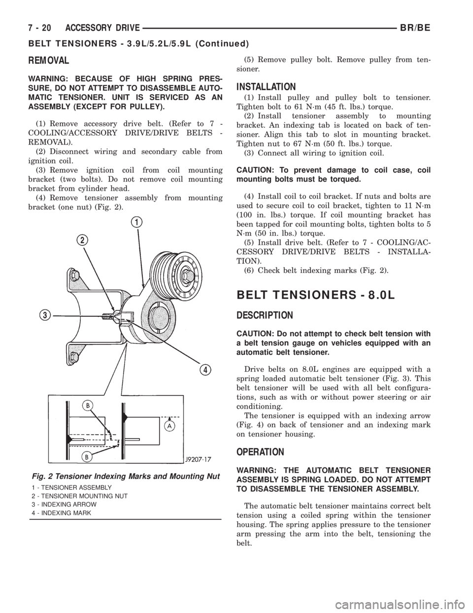
(4) Remove tensioner assembly from mounting
bracket (one nut) (Fig. 2).(5) Remove pulley bolt. Remove pulley from ten-
sioner.
INSTALLATION
(1) Install pulley and pulley bolt to tensioner.
Tighten bolt to 61 N´m (45 ft. lbs.) torque.
(2) Install tensioner assembly to mounting
bracket. An indexing tab is located on back of ten-
sioner. Align this tab to slot in mounting bracket.
Tighten nut to 67 N´m (50 ft. lbs.) torque.
(3) Connect all wiring to ignition coil.
CAUTION: To prevent damage to coil case, coil
mounting bolts must be torqued.
(4) Install coil to coil bracket. If nuts and bolts are
used to secure coil to coil bracket, tighten to 11 N´m
(100 in. lbs.) torque. If coil mounting bracket has
been tapped for coil mounting bolts, tighten bolts to 5
N´m (50 in. lbs.) torque.
(5) Install drive belt. (Refer to 7 - COOLING/AC-
CESSORY DRIVE/DRIVE BELTS - INSTALLA-
TION).
(6) Check belt indexing marks (Fig. 2).
BELT TENSIONERS - 8.0L
DESCRIPTION
CAUTION: Do not attempt to check belt tension with
a belt tension gauge on vehicles equipped with an
automatic belt tensioner.
Drive belts on 8.0L engines are equipped with a
spring loaded automatic belt tensioner (Fig. 3). This
belt tensioner will be used with all belt configura-
tions, such as with or without power steering or air
conditioning.
The tensioner is equipped with an indexing arrow
(Fig. 4) on back of tensioner and an indexing mark
on tensioner housing.
OPERATION
WARNING: THE AUTOMATIC BELT TENSIONER
ASSEMBLY IS SPRING LOADED. DO NOT ATTEMPT
TO DISASSEMBLE THE TENSIONER ASSEMBLY.
The automatic belt tensioner maintains correct belt
tension using a coiled spring within the tensioner
housing. The spring applies pressure to the tensioner
arm pressing the arm into the belt, tensioning the
belt.Fig. 2 Tensioner Indexing Marks and Mounting Nut
1 - TENSIONER ASSEMBLY
2 - TENSIONER MOUNTING NUT
3 - INDEXING ARROW
4 - INDEXING MARK
7 - 20 ACCESSORY DRIVEBR/BE
BELT TENSIONERS - 3.9L/5.2L/5.9L (Continued)
Page 383 of 2889
ENGINE COOLANT TEMP
SENSOR - 3.9L/5.2L/5.9L
DESCRIPTION
The Engine Coolant Temperature (ECT) sensor is
used to sense engine coolant temperature. The sensor
protrudes into an engine water jacket.
The ECT sensor is a two-wire Negative Thermal
Coefficient (NTC) sensor. Meaning, as engine coolant
temperature increases, resistance (voltage) in the
sensor decreases. As temperature decreases, resis-
tance (voltage) in the sensor increases.
OPERATION
At key-on, the Powertrain Control Module (PCM)
sends out a regulated 5 volt signal to the ECT sensor.
The PCM then monitors the signal as it passes
through the ECT sensor to the sensor ground (sensor
return).
When the engine is cold, the PCM will operate in
Open Loop cycle. It will demand slightly richer air-
fuel mixtures and higher idle speeds. This is done
until normal operating temperatures are reached.
The PCM uses inputs from the ECT sensor for the
following calculations:
²for engine coolant temperature gauge operation
through CCD or PCI (J1850) communications
²Injector pulse-width
²Spark-advance curves
²ASD relay shut-down times
²Idle Air Control (IAC) motor key-on steps
²Pulse-width prime-shot during cranking
²O2 sensor closed loop times
²Purge solenoid on/off times
²EGR solenoid on/off times (if equipped)
²Leak Detection Pump operation (if equipped)²Radiator fan relay on/off times (if equipped)
²Target idle speed
REMOVAL
WARNING: HOT, PRESSURIZED COOLANT CAN
CAUSE INJURY BY SCALDING. COOLING SYSTEM
MUST BE PARTIALLY DRAINED BEFORE REMOV-
ING THE COOLANT TEMPERATURE SENSOR.
REFER TO GROUP 7, COOLING.
(1) Partially drain cooling system (Refer to 7 -
COOLING - STANDARD PROCEDURE).
(2) Remove air cleaner assembly.
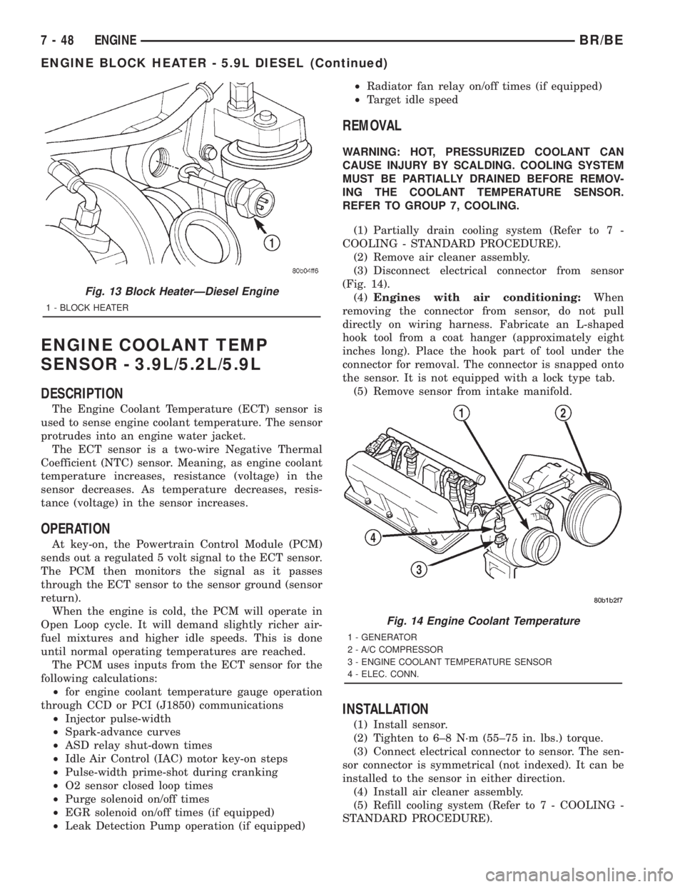
(3) Disconnect electrical connector from sensor
(Fig. 14).
(4)Engines with air conditioning:When
removing the connector from sensor, do not pull
directly on wiring harness. Fabricate an L-shaped
hook tool from a coat hanger (approximately eight
inches long). Place the hook part of tool under the
connector for removal. The connector is snapped onto
the sensor. It is not equipped with a lock type tab.
(5) Remove sensor from intake manifold.
INSTALLATION
(1) Install sensor.
(2) Tighten to 6±8 N´m (55±75 in. lbs.) torque.
(3) Connect electrical connector to sensor. The sen-
sor connector is symmetrical (not indexed). It can be
installed to the sensor in either direction.
(4) Install air cleaner assembly.
(5) Refill cooling system (Refer to 7 - COOLING -
STANDARD PROCEDURE).
Fig. 13 Block HeaterÐDiesel Engine
1 - BLOCK HEATER
Fig. 14 Engine Coolant Temperature
1 - GENERATOR
2 - A/C COMPRESSOR
3 - ENGINE COOLANT TEMPERATURE SENSOR
4 - ELEC. CONN.
7 - 48 ENGINEBR/BE
ENGINE BLOCK HEATER - 5.9L DIESEL (Continued)
Page 385 of 2889
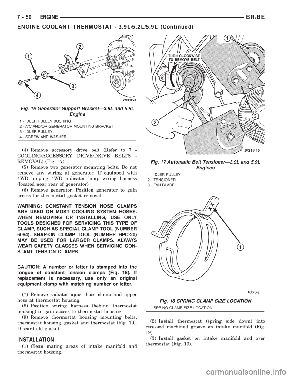
(4) Remove accessory drive belt (Refer to 7 -
COOLING/ACCESSORY DRIVE/DRIVE BELTS -
REMOVAL) (Fig. 17).
(5) Remove two generator mounting bolts. Do not
remove any wiring at generator. If equipped with
4WD, unplug 4WD indicator lamp wiring harness
(located near rear of generator).
(6) Remove generator. Position generator to gain
access for thermostat gasket removal.
WARNING: CONSTANT TENSION HOSE CLAMPS
ARE USED ON MOST COOLING SYSTEM HOSES.
WHEN REMOVING OR INSTALLING, USE ONLY
TOOLS DESIGNED FOR SERVICING THIS TYPE OF
CLAMP, SUCH AS SPECIAL CLAMP TOOL (NUMBER
6094). SNAP-ON CLAMP TOOL (NUMBER HPC-20)
MAY BE USED FOR LARGER CLAMPS. ALWAYS
WEAR SAFETY GLASSES WHEN SERVICING CON-
STANT TENSION CLAMPS.
CAUTION: A number or letter is stamped into the
tongue of constant tension clamps (Fig. 18). If
replacement is necessary, use only an original
equipment clamp with matching number or letter.
(7) Remove radiator upper hose clamp and upper
hose at thermostat housing.
(8) Position wiring harness (behind thermostat
housing) to gain access to thermostat housing.
(9) Remove thermostat housing mounting bolts,
thermostat housing, gasket and thermostat (Fig. 19).
Discard old gasket.
INSTALLATION
(1) Clean mating areas of intake manifold and
thermostat housing.(2) Install thermostat (spring side down) into
recessed machined groove on intake manifold (Fig.
19).
(3) Install gasket on intake manifold and over
thermostat (Fig. 19).
Fig. 16 Generator Support BracketÐ3.9L and 5.9L
Engine
1 - IDLER PULLEY BUSHING
2 - A/C AND/OR GENERATOR MOUNTING BRACKET
3 - IDLER PULLEY
4 - SCREW AND WASHER
Fig. 17 Automatic Belt TensionerÐ3.9L and 5.9L
Engines
1 - IDLER PULLEY
2 - TENSIONER
3 - FAN BLADE
Fig. 18 SPRING CLAMP SIZE LOCATION
1 - SPRING CLAMP SIZE LOCATION
7 - 50 ENGINEBR/BE
ENGINE COOLANT THERMOSTAT - 3.9L/5.2L/5.9L (Continued)
Page 388 of 2889
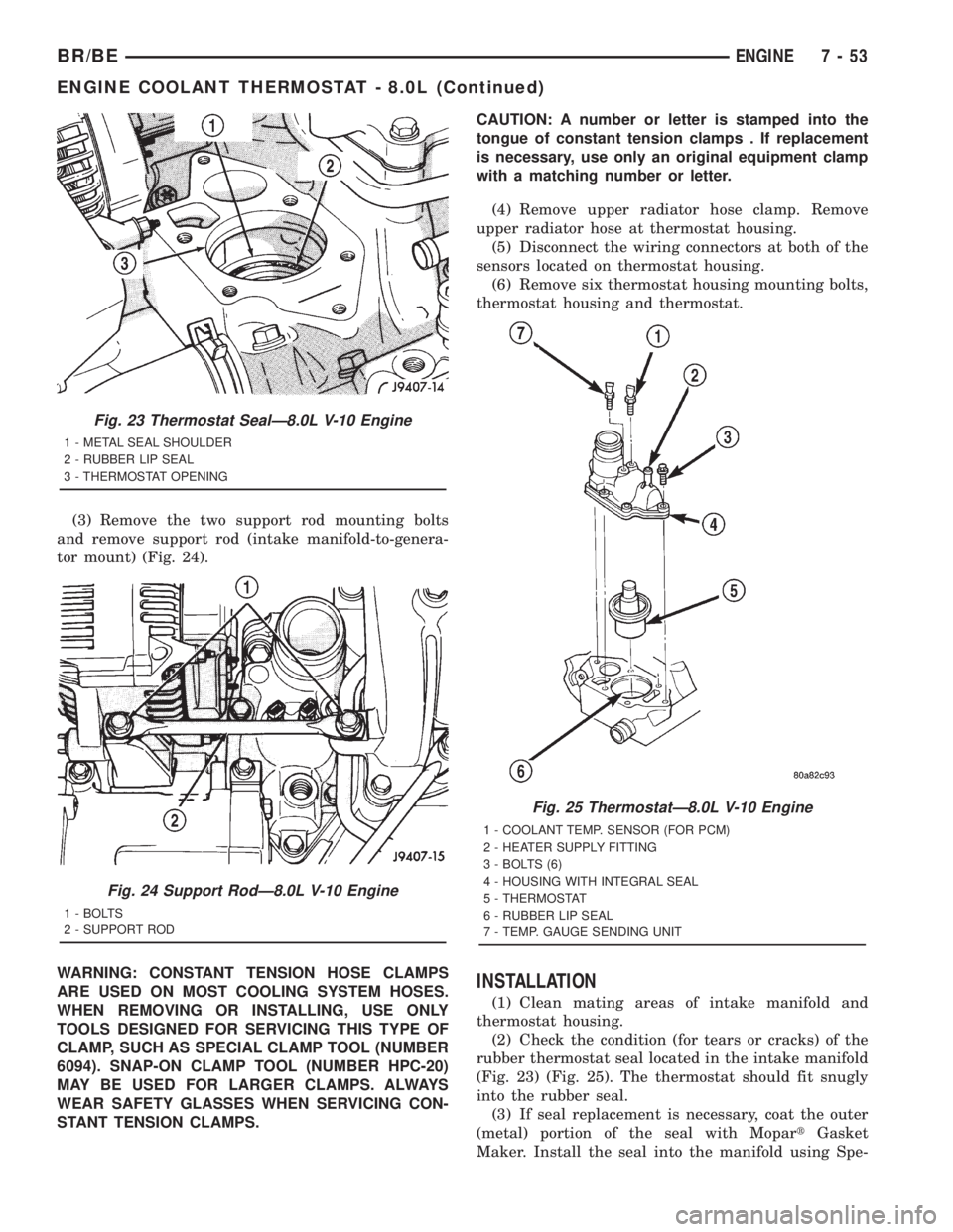
(3) Remove the two support rod mounting bolts
and remove support rod (intake manifold-to-genera-
tor mount) (Fig. 24).
WARNING: CONSTANT TENSION HOSE CLAMPS
ARE USED ON MOST COOLING SYSTEM HOSES.
WHEN REMOVING OR INSTALLING, USE ONLY
TOOLS DESIGNED FOR SERVICING THIS TYPE OF
CLAMP, SUCH AS SPECIAL CLAMP TOOL (NUMBER
6094). SNAP-ON CLAMP TOOL (NUMBER HPC-20)
MAY BE USED FOR LARGER CLAMPS. ALWAYS
WEAR SAFETY GLASSES WHEN SERVICING CON-
STANT TENSION CLAMPS.CAUTION: A number or letter is stamped into the
tongue of constant tension clamps . If replacement
is necessary, use only an original equipment clamp
with a matching number or letter.
(4) Remove upper radiator hose clamp. Remove
upper radiator hose at thermostat housing.
(5) Disconnect the wiring connectors at both of the
sensors located on thermostat housing.
(6) Remove six thermostat housing mounting bolts,
thermostat housing and thermostat.
INSTALLATION
(1) Clean mating areas of intake manifold and
thermostat housing.
(2) Check the condition (for tears or cracks) of the
rubber thermostat seal located in the intake manifold
(Fig. 23) (Fig. 25). The thermostat should fit snugly
into the rubber seal.
(3) If seal replacement is necessary, coat the outer
(metal) portion of the seal with MopartGasket
Maker. Install the seal into the manifold using Spe-
Fig. 23 Thermostat SealÐ8.0L V-10 Engine
1 - METAL SEAL SHOULDER
2 - RUBBER LIP SEAL
3 - THERMOSTAT OPENING
Fig. 24 Support RodÐ8.0L V-10 Engine
1 - BOLTS
2 - SUPPORT ROD
Fig. 25 ThermostatÐ8.0L V-10 Engine
1 - COOLANT TEMP. SENSOR (FOR PCM)
2 - HEATER SUPPLY FITTING
3 - BOLTS (6)
4 - HOUSING WITH INTEGRAL SEAL
5 - THERMOSTAT
6 - RUBBER LIP SEAL
7 - TEMP. GAUGE SENDING UNIT
BR/BEENGINE 7 - 53
ENGINE COOLANT THERMOSTAT - 8.0L (Continued)