DODGE RAM 2002 Service Repair Manual
Manufacturer: DODGE, Model Year: 2002, Model line: RAM, Model: DODGE RAM 2002Pages: 2255, PDF Size: 62.07 MB
Page 1221 of 2255
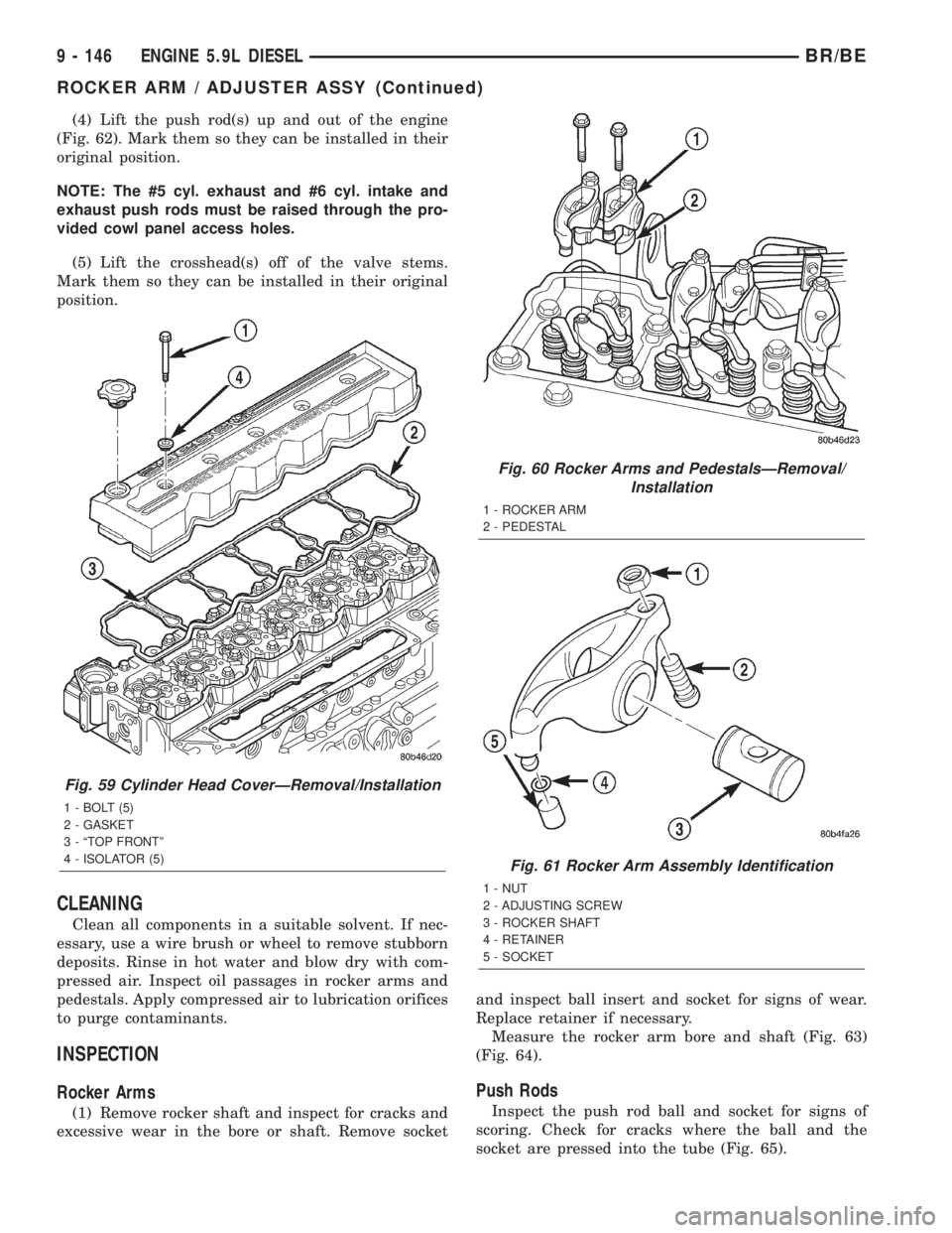
(4) Lift the push rod(s) up and out of the engine
(Fig. 62). Mark them so they can be installed in their
original position.
NOTE: The #5 cyl. exhaust and #6 cyl. intake and
exhaust push rods must be raised through the pro-
vided cowl panel access holes.
(5) Lift the crosshead(s) off of the valve stems.
Mark them so they can be installed in their original
position.
CLEANING
Clean all components in a suitable solvent. If nec-
essary, use a wire brush or wheel to remove stubborn
deposits. Rinse in hot water and blow dry with com-
pressed air. Inspect oil passages in rocker arms and
pedestals. Apply compressed air to lubrication orifices
to purge contaminants.
INSPECTION
Rocker Arms
(1) Remove rocker shaft and inspect for cracks and
excessive wear in the bore or shaft. Remove socketand inspect ball insert and socket for signs of wear.
Replace retainer if necessary.
Measure the rocker arm bore and shaft (Fig. 63)
(Fig. 64).
Push Rods
Inspect the push rod ball and socket for signs of
scoring. Check for cracks where the ball and the
socket are pressed into the tube (Fig. 65).
Fig. 59 Cylinder Head CoverÐRemoval/Installation
1 - BOLT (5)
2 - GASKET
3 - ªTOP FRONTº
4 - ISOLATOR (5)
Fig. 60 Rocker Arms and PedestalsÐRemoval/
Installation
1 - ROCKER ARM
2 - PEDESTAL
Fig. 61 Rocker Arm Assembly Identification
1 - NUT
2 - ADJUSTING SCREW
3 - ROCKER SHAFT
4 - RETAINER
5 - SOCKET
9 - 146 ENGINE 5.9L DIESELBR/BE
ROCKER ARM / ADJUSTER ASSY (Continued)
Page 1222 of 2255
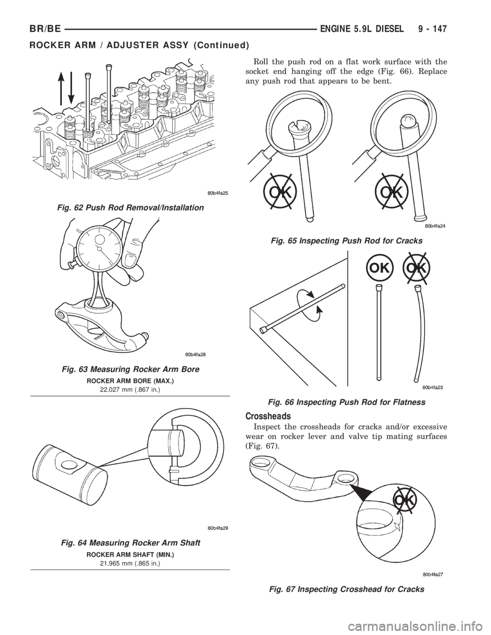
Roll the push rod on a flat work surface with the
socket end hanging off the edge (Fig. 66). Replace
any push rod that appears to be bent.
Crossheads
Inspect the crossheads for cracks and/or excessive
wear on rocker lever and valve tip mating surfaces
(Fig. 67).
Fig. 62 Push Rod Removal/Installation
Fig. 63 Measuring Rocker Arm Bore
ROCKER ARM BORE (MAX.)
22.027 mm (.867 in.)
Fig. 64 Measuring Rocker Arm Shaft
ROCKER ARM SHAFT (MIN.)
21.965 mm (.865 in.)
Fig. 65 Inspecting Push Rod for Cracks
Fig. 66 Inspecting Push Rod for Flatness
Fig. 67 Inspecting Crosshead for Cracks
BR/BEENGINE 5.9L DIESEL 9 - 147
ROCKER ARM / ADJUSTER ASSY (Continued)
Page 1223 of 2255
INSTALLATION
(1) If previously removed, install the push rods in
their original location (Fig. 62).Verify that they
are seated in the tappets.
(2) Lubricate the valve tips and install the cross-
heads in their original locations.
(3) Lubricate the crossheads and push rod sockets
and install the rocker arms and pedestals (Fig. 60) in
their original locations. Tighten bolts to 36 N´m (27
ft. lbs.) torque.
(4)Verify valve lash adjustment (Refer to 9 -
ENGINE/CYLINDER HEAD/INTAKE/EXHAUST
VALVES & SEATS - STANDARD PROCEDURE).
(5) Install cylinder head cover and reusable gasket
(Fig. 59) (Refer to 9 - ENGINE/CYLINDER HEAD/
CYLINDER HEAD COVER(S) - INSTALLATION).
(6) Connect battery negative cables.
ENGINE BLOCK
STANDARD PROCEDURE
STANDARD PROCEDURE - CYLINDER BLOCK
REFACING
(1) The combustion deck can be refaced twice. The
first reface should be 0.25 mm (0.0098 inch). If addi-
tional refacing is required, an additional 0.25 mm
(0.0098 inch) can be removed. Total allowed refacing
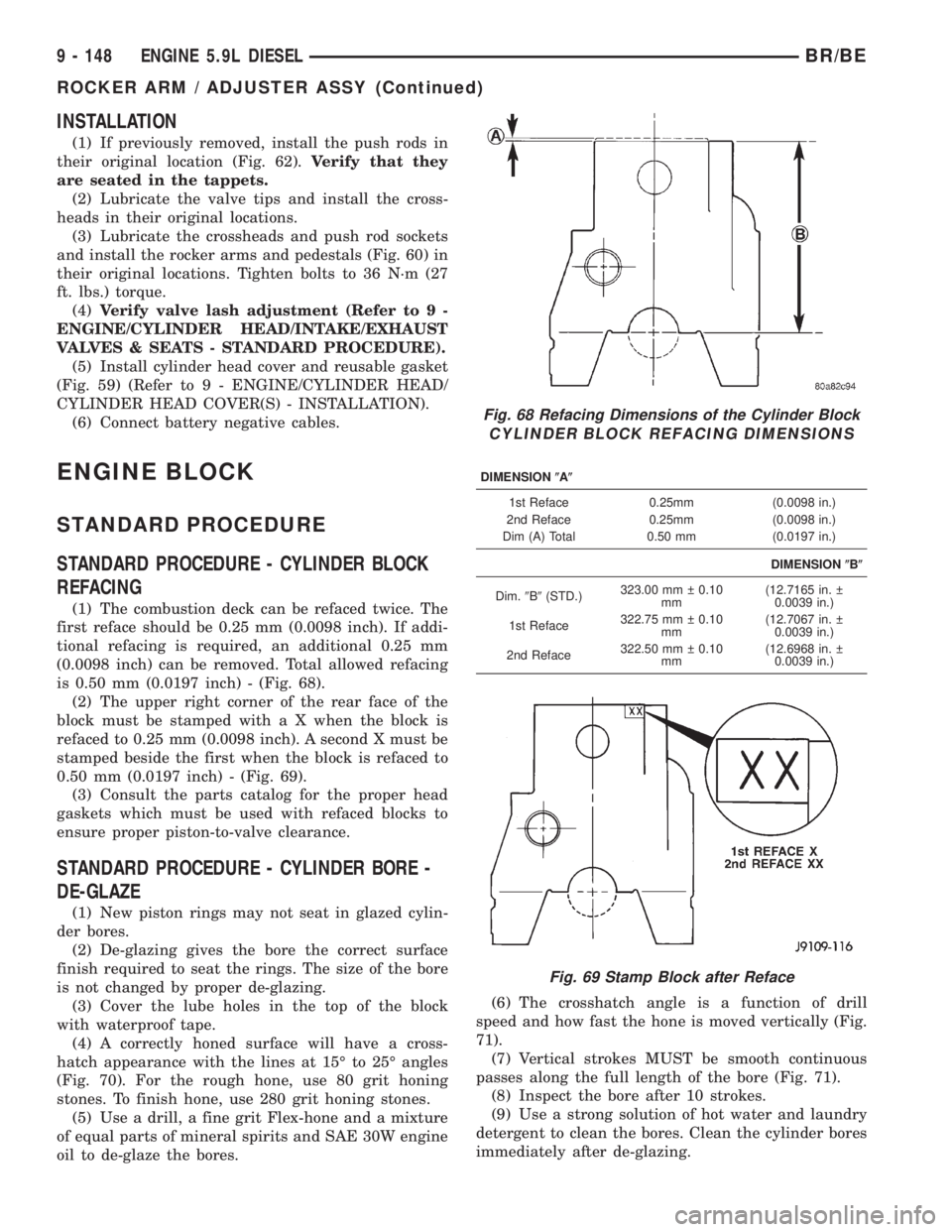
is 0.50 mm (0.0197 inch) - (Fig. 68).
(2) The upper right corner of the rear face of the
block must be stamped with a X when the block is
refaced to 0.25 mm (0.0098 inch). A second X must be
stamped beside the first when the block is refaced to
0.50 mm (0.0197 inch) - (Fig. 69).
(3) Consult the parts catalog for the proper head
gaskets which must be used with refaced blocks to
ensure proper piston-to-valve clearance.
STANDARD PROCEDURE - CYLINDER BORE -
DE-GLAZE
(1) New piston rings may not seat in glazed cylin-
der bores.
(2) De-glazing gives the bore the correct surface
finish required to seat the rings. The size of the bore
is not changed by proper de-glazing.
(3) Cover the lube holes in the top of the block
with waterproof tape.
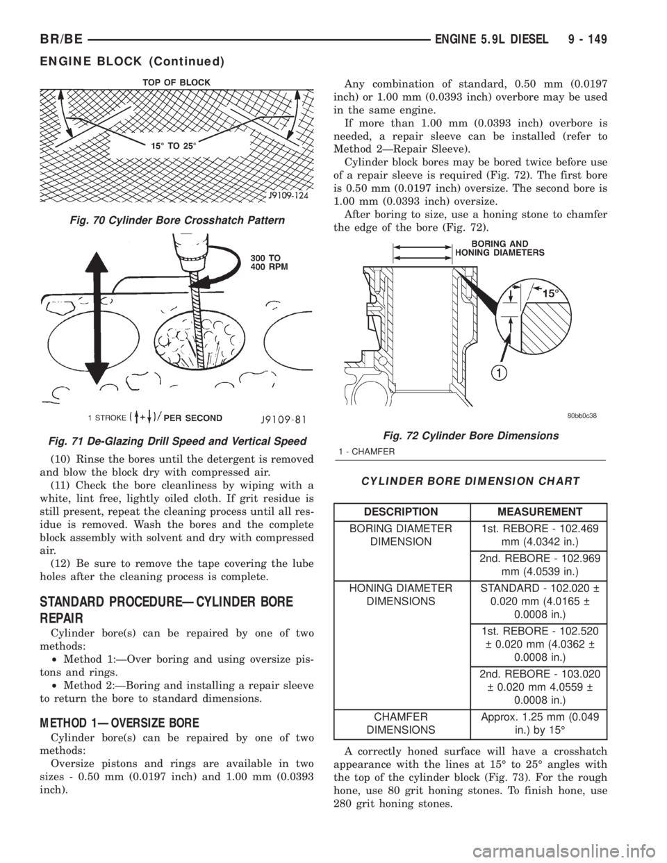
(4) A correctly honed surface will have a cross-
hatch appearance with the lines at 15É to 25É angles
(Fig. 70). For the rough hone, use 80 grit honing
stones. To finish hone, use 280 grit honing stones.
(5) Use a drill, a fine grit Flex-hone and a mixture
of equal parts of mineral spirits and SAE 30W engine
oil to de-glaze the bores.(6) The crosshatch angle is a function of drill
speed and how fast the hone is moved vertically (Fig.
71).
(7) Vertical strokes MUST be smooth continuous
passes along the full length of the bore (Fig. 71).
(8) Inspect the bore after 10 strokes.
(9) Use a strong solution of hot water and laundry
detergent to clean the bores. Clean the cylinder bores
immediately after de-glazing.
Fig. 68 Refacing Dimensions of the Cylinder Block
CYLINDER BLOCK REFACING DIMENSIONS
DIMENSION(A(
1st Reface 0.25mm (0.0098 in.)
2nd Reface 0.25mm (0.0098 in.)
Dim (A) Total 0.50 mm (0.0197 in.)
DIMENSION(B(
Dim.9B9(STD.)323.00 mm 0.10
mm(12.7165 in.
0.0039 in.)
1st Reface322.75 mm 0.10
mm(12.7067 in.
0.0039 in.)
2nd Reface322.50 mm 0.10
mm(12.6968 in.
0.0039 in.)
Fig. 69 Stamp Block after Reface
9 - 148 ENGINE 5.9L DIESELBR/BE
ROCKER ARM / ADJUSTER ASSY (Continued)
Page 1224 of 2255
(10) Rinse the bores until the detergent is removed
and blow the block dry with compressed air.
(11) Check the bore cleanliness by wiping with a
white, lint free, lightly oiled cloth. If grit residue is
still present, repeat the cleaning process until all res-
idue is removed. Wash the bores and the complete
block assembly with solvent and dry with compressed
air.
(12) Be sure to remove the tape covering the lube
holes after the cleaning process is complete.
STANDARD PROCEDUREÐCYLINDER BORE
REPAIR
Cylinder bore(s) can be repaired by one of two
methods:
²Method 1:ÐOver boring and using oversize pis-
tons and rings.
²Method 2:ÐBoring and installing a repair sleeve
to return the bore to standard dimensions.
METHOD 1ÐOVERSIZE BORE
Cylinder bore(s) can be repaired by one of two
methods:
Oversize pistons and rings are available in two
sizes - 0.50 mm (0.0197 inch) and 1.00 mm (0.0393
inch).Any combination of standard, 0.50 mm (0.0197
inch) or 1.00 mm (0.0393 inch) overbore may be used
in the same engine.
If more than 1.00 mm (0.0393 inch) overbore is
needed, a repair sleeve can be installed (refer to
Method 2ÐRepair Sleeve).
Cylinder block bores may be bored twice before use
of a repair sleeve is required (Fig. 72). The first bore
is 0.50 mm (0.0197 inch) oversize. The second bore is
1.00 mm (0.0393 inch) oversize.
After boring to size, use a honing stone to chamfer
the edge of the bore (Fig. 72).
CYLINDER BORE DIMENSION CHART
DESCRIPTION MEASUREMENT
BORING DIAMETER
DIMENSION1st. REBORE - 102.469
mm (4.0342 in.)
2nd. REBORE - 102.969
mm (4.0539 in.)
HONING DIAMETER
DIMENSIONSSTANDARD - 102.020
0.020 mm (4.0165
0.0008 in.)
1st. REBORE - 102.520
0.020 mm (4.0362
0.0008 in.)
2nd. REBORE - 103.020
0.020 mm 4.0559
0.0008 in.)
CHAMFER
DIMENSIONSApprox. 1.25 mm (0.049
in.) by 15É
A correctly honed surface will have a crosshatch
appearance with the lines at 15É to 25É angles with
the top of the cylinder block (Fig. 73). For the rough
hone, use 80 grit honing stones. To finish hone, use
280 grit honing stones.
Fig. 70 Cylinder Bore Crosshatch Pattern
Fig. 71 De-Glazing Drill Speed and Vertical SpeedFig. 72 Cylinder Bore Dimensions
1 - CHAMFER
BR/BEENGINE 5.9L DIESEL 9 - 149
ENGINE BLOCK (Continued)
Page 1225 of 2255
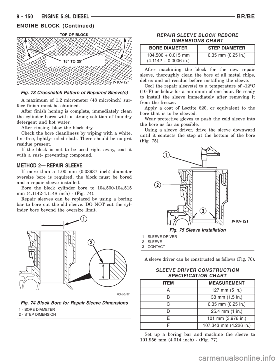
A maximum of 1.2 micrometer (48 microinch) sur-
face finish must be obtained.
After finish honing is complete, immediately clean
the cylinder bores with a strong solution of laundry
detergent and hot water.
After rinsing, blow the block dry.
Check the bore cleanliness by wiping with a white,
lint-free, lightly- oiled cloth. There should be no grit
residue present.
If the block is not to be used right away, coat it
with a rust- preventing compound.
METHOD 2ÐREPAIR SLEEVE
If more than a 1.00 mm (0.03937 inch) diameter
oversize bore is required, the block must be bored
and a repair sleeve installed.
Bore the block cylinder bore to 104.500-104.515
mm (4.1142-4.1148 inch) - (Fig. 74).
Repair sleeves can be replaced by using a boring
bar to bore out the old sleeve. DO NOT cut the cyl-
inder bore beyond the oversize limit.
REPAIR SLEEVE BLOCK REBORE
DIMENSIONS CHART
BORE DIAMETER STEP DIAMETER
104.500 + 0.015 mm
(4.1142 + 0.0006 in.)6.35 mm (0.25 in.)
After machining the block for the new repair
sleeve, thoroughly clean the bore of all metal chips,
debris and oil residue before installing the sleeve.
Cool the repair sleeve(s) to a temperature of -12ÉC
(10ÉF) or below for a minimum of one hour. Be ready
to install the sleeve immediately after removing it
from the freezer.
Apply a coat of Loctite 620, or equivalent to the
bore that is to be sleeved.
Wear protective gloves to push the cold sleeve into
the bore as far as possible.
Using a sleeve driver, drive the sleeve downward
until it contacts the step at the bottom of the bore
(Fig. 75).
A sleeve driver can be constructed as follows (Fig. 76).
SLEEVE DRIVER CONSTRUCTION
SPECIFICATION CHART
ITEM MEASUREMENT
A 127 mm (5 in.)
B 38 mm (1.5 in.)
C 6.35 mm (0.25 in.)
D 25.4 mm (1 in.)
E 101 mm (3.976 in.)
F 107.343 mm (4.226 in.)
Set up a boring bar and machine the sleeve to
101.956 mm (4.014 inch) - (Fig. 77).
Fig. 73 Crosshatch Pattern of Repaired Sleeve(s)
Fig. 74 Block Bore for Repair Sleeve Dimensions
1 - BORE DIAMETER
2 - STEP DIMENSION
Fig. 75 Sleeve Installation
1 - SLEEVE DRIVER
2 - SLEEVE
3 - CONTACT
9 - 150 ENGINE 5.9L DIESELBR/BE
ENGINE BLOCK (Continued)
Page 1226 of 2255
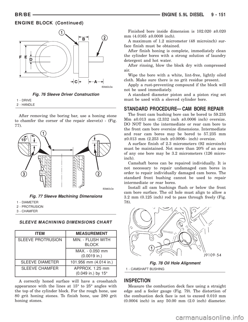
After removing the boring bar, use a honing stone
to chamfer the corner of the repair sleeve(s) - (Fig.
77).
SLEEVE MACHINING DIMENSIONS CHART
ITEM MEASUREMENT
SLEEVE PROTRUSION MIN. - FLUSH WITH
BLOCK
MAX. - 0.050 mm
(0.0019 in.)
SLEEVE DIAMETER 101.956 mm (4.014 in.)
SLEEVE CHAMFER APPROX. 1.25 mm
(0.049 in.) by 15É
A correctly honed surface will have a crosshatch
appearance with the lines at 15É to 25É angles with
the top of the cylinder block. For the rough hone, use
80 grit honing stones. To finish hone, use 280 grit
honing stones.Finished bore inside dimension is 102.020 0.020
mm (4.0165 0.0008 inch).
A maximum of 1.2 micrometer (48 microinch) sur-
face finish must be obtained.
After finish honing is complete, immediately clean
the cylinder bores with a strong solution of laundry
detergent and hot water.
After rinsing, blow the block dry with compressed
air.
Wipe the bore with a white, lint-free, lightly oiled
cloth. Make sure there is no grit residue present.
Apply a rust-preventing compound if the block will
not be used immediately.
A standard diameter piston and a piston ring set
must be used with a sleeved cylinder bore.
STANDARD PROCEDUREÐCAM BORE REPAIR
The front cam bushing bore can be bored to 59.235
Mm 0.013 mm (2.332 inch 0.0006 inch) oversize.
DO NOT bore the intermediate or rear cam bore to
the front cam bore oversize dimensions. Intermediate
and rear cam bores may be bored to 57.235 mm
0.013 mm (2.253 inch 0.0006± inch) oversize.
A surface finish of 2.3 micrometers (92 microinch)
must be maintained. Not more than 20% of an area
of any one bore may be 3.2 micrometers (126 micro-
inch).
Camshaft bores can be repaired individually. It is
not necessary to repair undamaged cam bores in
order to repair individually damaged cam bores. The
standard front bushing cannot be used to repair
intermediate or rear bores.
Install all cam bushings flush or below the front
cam bore surface. The oil hole must align to allow a
3.2 mm (0.125 inch) rod to pass through freely (Fig.
78).
INSPECTION
Measure the combustion deck face using a straight
edge and a feeler gauge (Fig. 79). The distortion of
the combustion deck face is not to exceed 0.010 mm
(0.0004 inch) in any 50.00 mm (2.0 inch) diameter.
Fig. 76 Sleeve Driver Construction
1 - DRIVE
2 - HANDLE
Fig. 77 Sleeve Machining Dimensions
1 - DIAMETER
2 - PROTRUSION
3 - CHAMFER
Fig. 78 Oil Hole Alignment
1 - CAMSHAFT BUSHING
BR/BEENGINE 5.9L DIESEL 9 - 151
ENGINE BLOCK (Continued)
Page 1227 of 2255
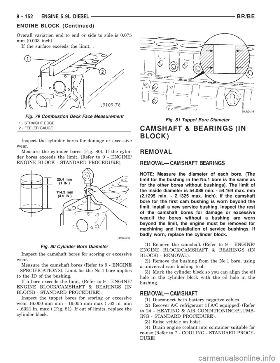
Overall variation end to end or side to side is 0.075
mm (0.003 inch).
If the surface exceeds the limit, .
Inspect the cylinder bores for damage or excessive
wear.
Measure the cylinder bores (Fig. 80). If the cylin-
der bores exceeds the limit, (Refer to 9 - ENGINE/
ENGINE BLOCK - STANDARD PROCEDURE).
Inspect the camshaft bores for scoring or excessive
wear.
Measure the camshaft bores (Refer to 9 - ENGINE
- SPECIFICATIONS). Limit for the No.1 bore applies
to the ID of the bushing.
If a bore exceeds the limit, (Refer to 9 - ENGINE/
ENGINE BLOCK/CAMSHAFT & BEARINGS (IN
BLOCK) - STANDARD PROCEDURE).
Inspect the tappet bores for scoring or excessive
wear 16.000 mm min - 16.055 mm max ( .63 in. min
- .6321 in. max ) (Fig. 81). If out of limits, replace the
cylinder block.
CAMSHAFT & BEARINGS (IN
BLOCK)
REMOVAL
REMOVALÐCAMSHAFT BEARINGS
NOTE: Measure the diameter of each bore. (The
limit for the bushing in the No.1 bore is the same as
for the other bores without bushings). The limit of
the inside diameter is 54.089 min. - 54.164 max. mm
(2.1295 min. - 2.1325 max. inch). If the camshaft
bore for the first cam bushing is worn beyond the
limit, install a new service bushing. Inspect the rest
of the camshaft bores for damage or excessive
wear.If the bores without a bushing are worn
beyond the limit, the engine must be removed for
machining and installation of service bushings. If
badly worn, replace the cylinder block.
(1) Remove the camshaft (Refer to 9 - ENGINE/
ENGINE BLOCK/CAMSHAFT & BEARINGS (IN
BLOCK) - REMOVAL).
(2) Remove the bushing from the No.1 bore, using
a universal cam bushing tool.
(3) Mark the cylinder block so you can align the oil
hole in the cylinder block with the oil hole in the
bushing.
REMOVALÐCAMSHAFT
(1) Disconnect both battery negative cables.
(2) Recover A/C refrigerant (if A/C equipped) (Refer
to 24 - HEATING & AIR CONDITIONING/PLUMB-
ING - STANDARD PROCEDURE).
(3) Raise vehicle on hoist.
(4) Drain engine coolant into container suitable for
re-use (Refer to 7 - COOLING - STANDARD PROCE-
DURE).
Fig. 79 Combustion Deck Face Measurement
1 - STRAIGHT EDGE
2 - FEELER GAUGE
Fig. 80 Cylinder Bore Diameter
Fig. 81 Tappet Bore Diameter
9 - 152 ENGINE 5.9L DIESELBR/BE
ENGINE BLOCK (Continued)
Page 1228 of 2255
(5) Lower vehicle.
(6) Remove radiator upper hose.
(7) Remove viscous fan/drive assembly and fan
shroud (Refer to 7 - COOLING/ENGINE/RADIATOR
FAN - REMOVAL).
(8) Disconnect the coolant recovery bottle hose
from the radiator filler neck.
(9) Disconnect lower radiator hose from radiator
outlet.
(10)Automatic Transmission models:Discon-
nect transmission oil cooler lines from radiator using
Special Tool 6931 (unless equipped with finger-re-
lease disconnect).
(11) Remove radiator mounting screws and lift
radiator out of engine compartment.
(12) Remove upper radiator support panel.
(13) Remove front bumper assembly (Refer to 13 -
FRAMES & BUMPERS/BUMPERS/FRONT
BUMPER - REMOVAL).
(14) If A/C equipped, disconnect A/C condenser
refrigerant lines.
(15) Disconnect charge air cooler piping from the
cooler inlet and outlet.
(16) Remove the two charge air cooler mounting
bolts.
(17) Remove charge air cooler (and A/C condenser
if equipped) from vehicle.
(18) Remove accessory drive belt (Refer to 7 -
COOLING/ACCESSORY DRIVE/DRIVE BELTS -
REMOVAL).
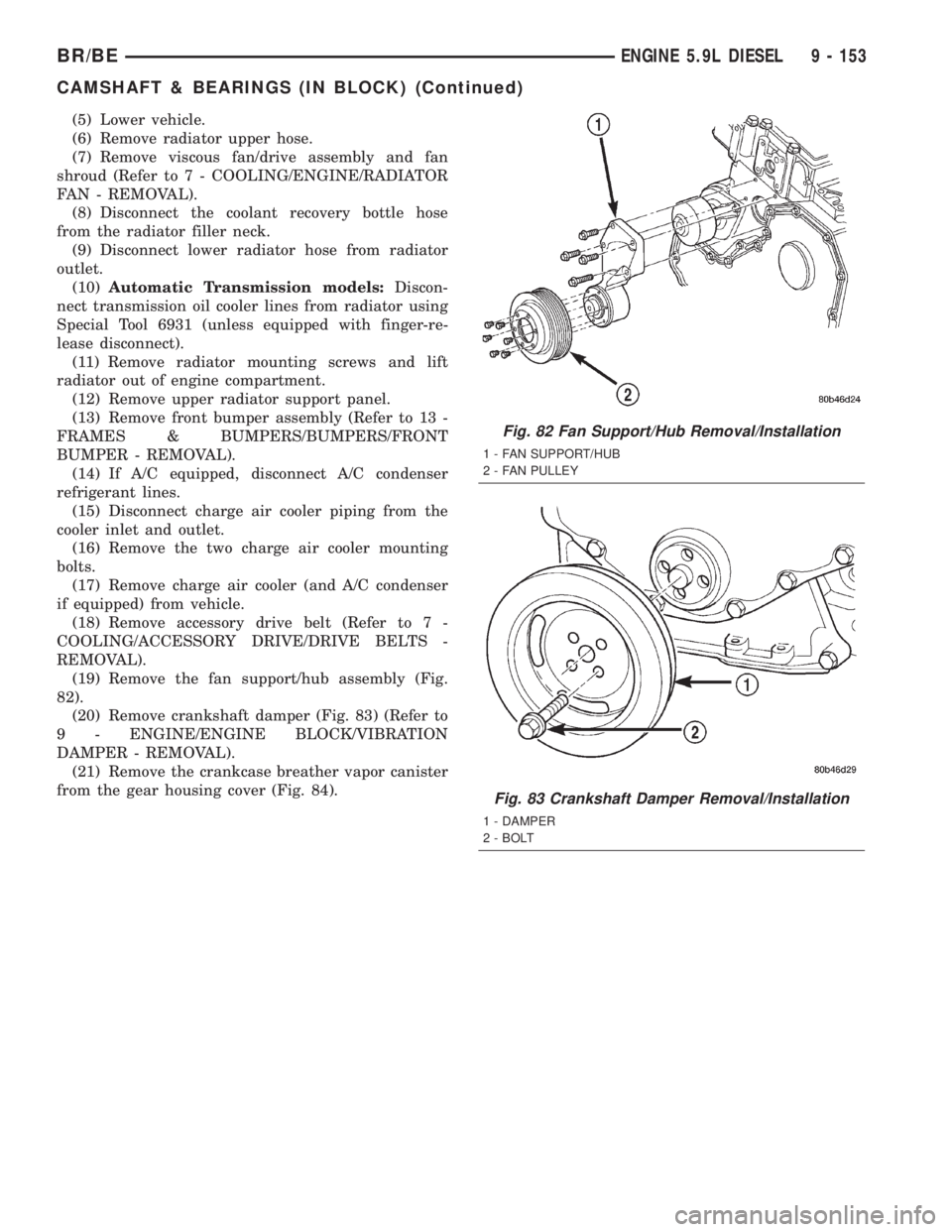
(19) Remove the fan support/hub assembly (Fig.
82).
(20) Remove crankshaft damper (Fig. 83) (Refer to
9 - ENGINE/ENGINE BLOCK/VIBRATION
DAMPER - REMOVAL).
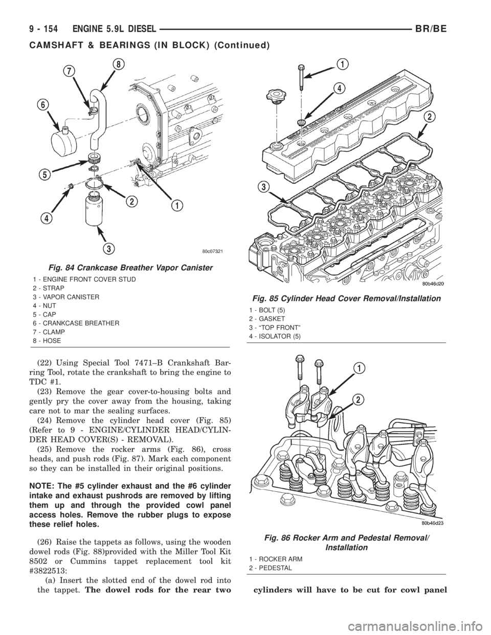
(21) Remove the crankcase breather vapor canister
from the gear housing cover (Fig. 84).
Fig. 82 Fan Support/Hub Removal/Installation
1 - FAN SUPPORT/HUB
2 - FAN PULLEY
Fig. 83 Crankshaft Damper Removal/Installation
1 - DAMPER
2 - BOLT
BR/BEENGINE 5.9L DIESEL 9 - 153
CAMSHAFT & BEARINGS (IN BLOCK) (Continued)
Page 1229 of 2255
(22) Using Special Tool 7471±B Crankshaft Bar-
ring Tool, rotate the crankshaft to bring the engine to
TDC #1.
(23) Remove the gear cover-to-housing bolts and
gently pry the cover away from the housing, taking
care not to mar the sealing surfaces.
(24) Remove the cylinder head cover (Fig. 85)
(Refer to 9 - ENGINE/CYLINDER HEAD/CYLIN-
DER HEAD COVER(S) - REMOVAL).
(25) Remove the rocker arms (Fig. 86), cross
heads, and push rods (Fig. 87). Mark each component
so they can be installed in their original positions.
NOTE: The #5 cylinder exhaust and the #6 cylinder
intake and exhaust pushrods are removed by lifting
them up and through the provided cowl panel
access holes. Remove the rubber plugs to expose
these relief holes.
(26) Raise the tappets as follows, using the wooden
dowel rods (Fig. 88)provided with the Miller Tool Kit
8502 or Cummins tappet replacement tool kit
#3822513:
(a) Insert the slotted end of the dowel rod into
the tappet.The dowel rods for the rear twocylinders will have to be cut for cowl panel
Fig. 84 Crankcase Breather Vapor Canister
1 - ENGINE FRONT COVER STUD
2 - STRAP
3 - VAPOR CANISTER
4 - NUT
5 - CAP
6 - CRANKCASE BREATHER
7 - CLAMP
8 - HOSE
Fig. 85 Cylinder Head Cover Removal/Installation
1 - BOLT (5)
2 - GASKET
3 - ªTOP FRONTº
4 - ISOLATOR (5)
Fig. 86 Rocker Arm and Pedestal Removal/
Installation
1 - ROCKER ARM
2 - PEDESTAL
9 - 154 ENGINE 5.9L DIESELBR/BE
CAMSHAFT & BEARINGS (IN BLOCK) (Continued)
Page 1230 of 2255
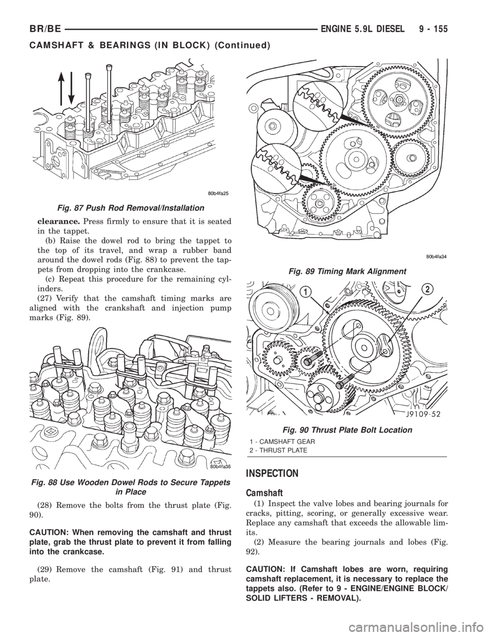
clearance.Press firmly to ensure that it is seated
in the tappet.
(b) Raise the dowel rod to bring the tappet to
the top of its travel, and wrap a rubber band
around the dowel rods (Fig. 88) to prevent the tap-
pets from dropping into the crankcase.
(c) Repeat this procedure for the remaining cyl-
inders.
(27) Verify that the camshaft timing marks are
aligned with the crankshaft and injection pump
marks (Fig. 89).
(28) Remove the bolts from the thrust plate (Fig.
90).
CAUTION: When removing the camshaft and thrust
plate, grab the thrust plate to prevent it from falling
into the crankcase.
(29) Remove the camshaft (Fig. 91) and thrust
plate.
INSPECTION
Camshaft
(1) Inspect the valve lobes and bearing journals for
cracks, pitting, scoring, or generally excessive wear.
Replace any camshaft that exceeds the allowable lim-
its.
(2) Measure the bearing journals and lobes (Fig.
92).
CAUTION: If Camshaft lobes are worn, requiring
camshaft replacement, it is necessary to replace the
tappets also. (Refer to 9 - ENGINE/ENGINE BLOCK/
SOLID LIFTERS - REMOVAL).
Fig. 87 Push Rod Removal/Installation
Fig. 88 Use Wooden Dowel Rods to Secure Tappets
in Place
Fig. 89 Timing Mark Alignment
Fig. 90 Thrust Plate Bolt Location
1 - CAMSHAFT GEAR
2 - THRUST PLATE
BR/BEENGINE 5.9L DIESEL 9 - 155
CAMSHAFT & BEARINGS (IN BLOCK) (Continued)