tire pressure DODGE RAM 2002 Service Owner's Manual
[x] Cancel search | Manufacturer: DODGE, Model Year: 2002, Model line: RAM, Model: DODGE RAM 2002Pages: 2255, PDF Size: 62.07 MB
Page 1545 of 2255
PARK POWERFLOW
As the engine is running and the crankshaft is
rotating, the flexplate and torque converter, which
are also bolted to it, are all rotating in a clockwise
direction as viewed from the front of the engine. The
notched hub of the torque converter is connected to
the oil pump's internal gear, supplying the transmis-
sion with oil pressure. As the converter turns, it
turns the input shaft in a clockwise direction. As the
input shaft is rotating, the front clutch hub-rear
clutch retainer and all their associated parts are also
rotating, all being directly connected to the input
shaft. The power flow from the engine through the
front clutch hub and rear clutch retainer stops at the
rear clutch retainer. Therefore, no power flow to the
output shaft occurs because no clutches are applied.
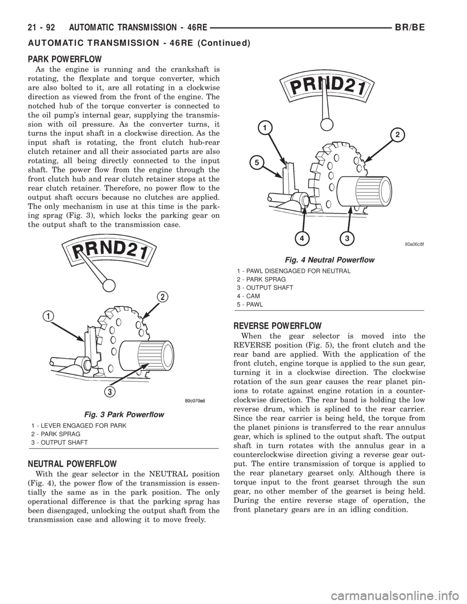
The only mechanism in use at this time is the park-
ing sprag (Fig. 3), which locks the parking gear on
the output shaft to the transmission case.
NEUTRAL POWERFLOW
With the gear selector in the NEUTRAL position
(Fig. 4), the power flow of the transmission is essen-
tially the same as in the park position. The only
operational difference is that the parking sprag has
been disengaged, unlocking the output shaft from the
transmission case and allowing it to move freely.
REVERSE POWERFLOW
When the gear selector is moved into the
REVERSE position (Fig. 5), the front clutch and the
rear band are applied. With the application of the
front clutch, engine torque is applied to the sun gear,
turning it in a clockwise direction. The clockwise
rotation of the sun gear causes the rear planet pin-
ions to rotate against engine rotation in a counter-
clockwise direction. The rear band is holding the low
reverse drum, which is splined to the rear carrier.
Since the rear carrier is being held, the torque from
the planet pinions is transferred to the rear annulus
gear, which is splined to the output shaft. The output
shaft in turn rotates with the annulus gear in a
counterclockwise direction giving a reverse gear out-
put. The entire transmission of torque is applied to
the rear planetary gearset only. Although there is
torque input to the front gearset through the sun
gear, no other member of the gearset is being held.
During the entire reverse stage of operation, the
front planetary gears are in an idling condition.
Fig. 3 Park Powerflow
1 - LEVER ENGAGED FOR PARK
2 - PARK SPRAG
3 - OUTPUT SHAFT
Fig. 4 Neutral Powerflow
1 - PAWL DISENGAGED FOR NEUTRAL
2 - PARK SPRAG
3 - OUTPUT SHAFT
4 - CAM
5-PAWL
21 - 92 AUTOMATIC TRANSMISSION - 46REBR/BE
AUTOMATIC TRANSMISSION - 46RE (Continued)
Page 1659 of 2255
(9) Install piston spring in retainer and on top of
piston. Concave side of spring faces downward
(toward piston).
(10) Install the spacer ring and wave spring into
the retainer. Be sure spring is completely seated in
retainer groove.
(11) Install pressure plate (Fig. 223). Ridged side
of plate faces downward (toward piston) and flat side
toward clutch pack.
(12) Install first clutch disc in retainer on top of
pressure plate. Then install a clutch plate followed
by a clutch disc until entire clutch pack is installed
(4 discs and 3 plates are required) (Fig. 223).
(13) Install the reaction plate.
(14) Install selective snap-ring. Be sure snap-ring
is fully seated in retainer groove.
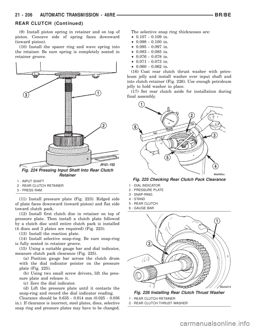
(15) Using a suitable gauge bar and dial indicator,
measure clutch pack clearance (Fig. 225).
(a) Position gauge bar across the clutch drum
with the dial indicator pointer on the pressure
plate (Fig. 225).
(b) Using two small screw drivers, lift the pres-
sure plate and release it.
(c) Zero the dial indicator.
(d) Lift the pressure plate until it contacts the
snap-ring and record the dial indicator reading.
Clearance should be 0.635 - 0.914 mm (0.025 - 0.036
in.). If clearance is incorrect, steel plates, discs, selective
snap ring and pressure plates may have to be changed.
The selective snap ring thicknesses are:
²0.107 - 0.109 in.
²0.098 - 0.100 in.
²0.095 - 0.097 in.
²0.083 - 0.085 in.
²0.076 - 0.078 in.
²0.071 - 0.073 in.
²0.060 - 0.062 in.
(16) Coat rear clutch thrust washer with petro-
leum jelly and install washer over input shaft and
into clutch retainer (Fig. 226). Use enough petroleum
jelly to hold washer in place.
(17) Set rear clutch aside for installation during
final assembly.
Fig. 224 Pressing Input Shaft Into Rear Clutch
Retainer
1 - INPUT SHAFT
2 - REAR CLUTCH RETAINER
3 - PRESS RAMFig. 225 Checking Rear Clutch Pack Clearance
1 - DIAL INDICATOR
2 - PRESSURE PLATE
3 - SNAP-RING
4-STAND
5 - REAR CLUTCH
6 - GAUGE BAR
Fig. 226 Installing Rear Clutch Thrust Washer
1 - REAR CLUTCH RETAINER
2 - REAR CLUTCH THRUST WASHER
21 - 206 AUTOMATIC TRANSMISSION - 46REBR/BE
REAR CLUTCH (Continued)
Page 1717 of 2255
PARK POWERFLOW
As the engine is running and the crankshaft is
rotating, the flexplate and torque converter, which
are also bolted to it, are all rotating in a clockwise
direction as viewed from the front of the engine. The
notched hub of the torque converter is connected to
the oil pump's internal gear, supplying the transmis-
sion with oil pressure. As the converter turns, it
turns the input shaft in a clockwise direction. As the
input shaft is rotating, the front clutch hub-rear
clutch retainer and all their associated parts are also
rotating, all being directly connected to the input
shaft. The power flow from the engine through the
front clutch hub and rear clutch retainer stops at the
rear clutch retainer. Therefore, no power flow to the
output shaft occurs because no clutches are applied.
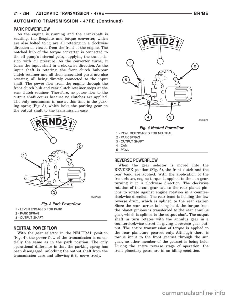
The only mechanism in use at this time is the park-
ing sprag (Fig. 3), which locks the parking gear on
the output shaft to the transmission case.
NEUTRAL POWERFLOW
With the gear selector in the NEUTRAL position
(Fig. 4), the power flow of the transmission is essen-
tially the same as in the park position. The only
operational difference is that the parking sprag has
been disengaged, unlocking the output shaft from the
transmission case and allowing it to move freely.
REVERSE POWERFLOW
When the gear selector is moved into the
REVERSE position (Fig. 5), the front clutch and the
rear band are applied. With the application of the
front clutch, engine torque is applied to the sun gear,
turning it in a clockwise direction. The clockwise
rotation of the sun gear causes the rear planet pin-
ions to rotate against engine rotation in a counter-
clockwise direction. The rear band is holding the low
reverse drum, which is splined to the rear carrier.
Since the rear carrier is being held, the torque from
the planet pinions is transferred to the rear annulus
gear, which is splined to the output shaft. The output
shaft in turn rotates with the annulus gear in a
counterclockwise direction giving a reverse gear out-
put. The entire transmission of torque is applied to
the rear planetary gearset only. Although there is
torque input to the front gearset through the sun
gear, no other member of the gearset is being held.
During the entire reverse stage of operation, the
front planetary gears are in an idling condition.
Fig. 3 Park Powerflow
1 - LEVER ENGAGED FOR PARK
2 - PARK SPRAG
3 - OUTPUT SHAFT
Fig. 4 Neutral Powerflow
1 - PAWL DISENGAGED FOR NEUTRAL
2 - PARK SPRAG
3 - OUTPUT SHAFT
4 - CAM
5-PAWL
21 - 264 AUTOMATIC TRANSMISSION - 47REBR/BE
AUTOMATIC TRANSMISSION - 47RE (Continued)
Page 1831 of 2255
(11) Install pressure plate (Fig. 223). Ridged side
of plate faces downward (toward piston) and flat side
toward clutch pack.
(12) Install first clutch disc in retainer on top of
pressure plate. Then install a clutch plate followed
by a clutch disc until entire clutch pack is installed
(4 discs and 3 plates are required) (Fig. 223).
(13) Install the reaction plate.
(14) Install selective snap-ring. Be sure snap-ring
is fully seated in retainer groove.
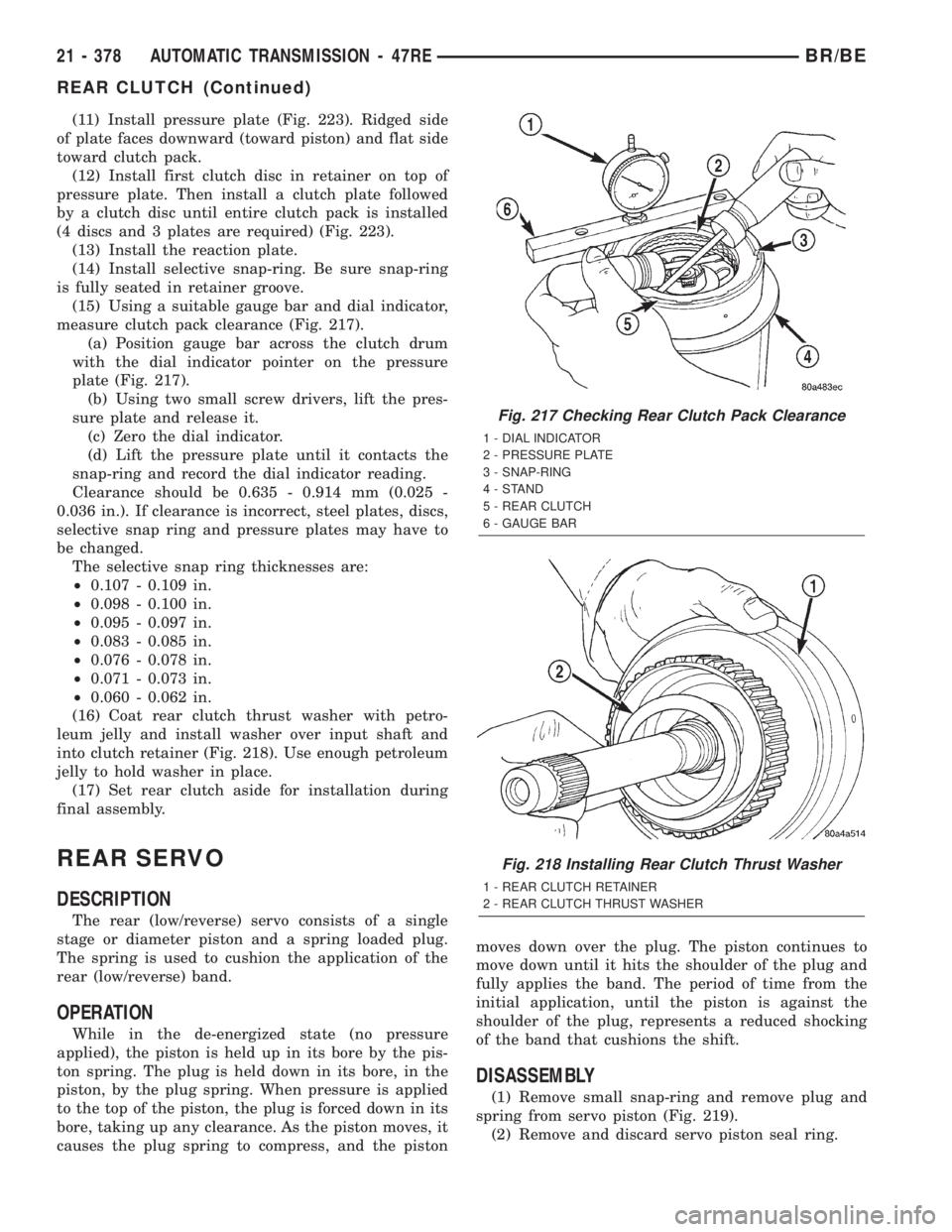
(15) Using a suitable gauge bar and dial indicator,
measure clutch pack clearance (Fig. 217).
(a) Position gauge bar across the clutch drum
with the dial indicator pointer on the pressure
plate (Fig. 217).
(b) Using two small screw drivers, lift the pres-
sure plate and release it.
(c) Zero the dial indicator.
(d) Lift the pressure plate until it contacts the
snap-ring and record the dial indicator reading.
Clearance should be 0.635 - 0.914 mm (0.025 -
0.036 in.). If clearance is incorrect, steel plates, discs,
selective snap ring and pressure plates may have to
be changed.
The selective snap ring thicknesses are:
²0.107 - 0.109 in.
²0.098 - 0.100 in.
²0.095 - 0.097 in.
²0.083 - 0.085 in.
²0.076 - 0.078 in.
²0.071 - 0.073 in.
²0.060 - 0.062 in.
(16) Coat rear clutch thrust washer with petro-
leum jelly and install washer over input shaft and
into clutch retainer (Fig. 218). Use enough petroleum
jelly to hold washer in place.
(17) Set rear clutch aside for installation during
final assembly.
REAR SERVO
DESCRIPTION
The rear (low/reverse) servo consists of a single
stage or diameter piston and a spring loaded plug.
The spring is used to cushion the application of the
rear (low/reverse) band.
OPERATION
While in the de-energized state (no pressure
applied), the piston is held up in its bore by the pis-
ton spring. The plug is held down in its bore, in the
piston, by the plug spring. When pressure is applied
to the top of the piston, the plug is forced down in its
bore, taking up any clearance. As the piston moves, it
causes the plug spring to compress, and the pistonmoves down over the plug. The piston continues to
move down until it hits the shoulder of the plug and
fully applies the band. The period of time from the
initial application, until the piston is against the
shoulder of the plug, represents a reduced shocking
of the band that cushions the shift.
DISASSEMBLY
(1) Remove small snap-ring and remove plug and
spring from servo piston (Fig. 219).
(2) Remove and discard servo piston seal ring.
Fig. 217 Checking Rear Clutch Pack Clearance
1 - DIAL INDICATOR
2 - PRESSURE PLATE
3 - SNAP-RING
4-STAND
5 - REAR CLUTCH
6 - GAUGE BAR
Fig. 218 Installing Rear Clutch Thrust Washer
1 - REAR CLUTCH RETAINER
2 - REAR CLUTCH THRUST WASHER
21 - 378 AUTOMATIC TRANSMISSION - 47REBR/BE
REAR CLUTCH (Continued)
Page 1956 of 2255
TIRES/WHEELS
TABLE OF CONTENTS
page page
TIRES/WHEELS
DIAGNOSIS AND TESTING - TIRE AND
WHEEL RUNOUT......................1
STANDARD PROCEDURE
STANDARD PROCEDURE -
TIRE ROTATION.......................2
STANDARD PROCEDURE - MATCH
MOUNTING...........................3
STANDARD PROCEDURE - TIRE AND
WHEEL BALANCE......................4
TIRES
DESCRIPTION
DESCRIPTION - SPARE TIRE - TEMPORARY...6
DESCRIPTION - TIRES..................6
DESCRIPTION - RADIAL-PLY TIRES........6
DESCRIPTION - TIRE PRESSURE FOR
HIGH SPEEDS.........................7
DESCRIPTION - REPLACEMENT TIRES.....7
DESCRIPTION - TIRE INFLATION
PRESSURES..........................7
DIAGNOSIS AND TESTING
DIAGNOSIS AND TESTING - PRESSURE
GAUGES.............................8
DIAGNOSIS AND TESTING - TREAD WEAR
INDICATORS..........................8
DIAGNOSIS AND TESTING - TIRE WEAR
PATTERNS...........................8DIAGNOSIS AND TESTING - TIRE NOISE
OR VIBRATION........................9
STANDARD PROCEDURE - REPAIRING
LEAKS...............................9
SPECIFICATIONS
TIRE REVOLUTIONS PER MILE...........9
SPARE TIRE
DESCRIPTION.........................10
WHEELS
DESCRIPTION.........................10
OPERATION...........................10
DIAGNOSIS AND TESTING
WHEEL INSPECTION..................11
STANDARD PROCEDURE - DUAL REAR
WHEEL INSTALLATION.................11
SPECIFICATIONS
TORQUE CHART......................11
STUDS
REMOVAL.............................12
INSTALLATION.........................12
WHEEL COVER
REMOVAL.............................12
INSTALLATION
INSTALLATION - REAR.................12
INSTALLATION - FRONT................12
TIRES/WHEELS
DIAGNOSIS AND TESTING - TIRE AND WHEEL
RUNOUT
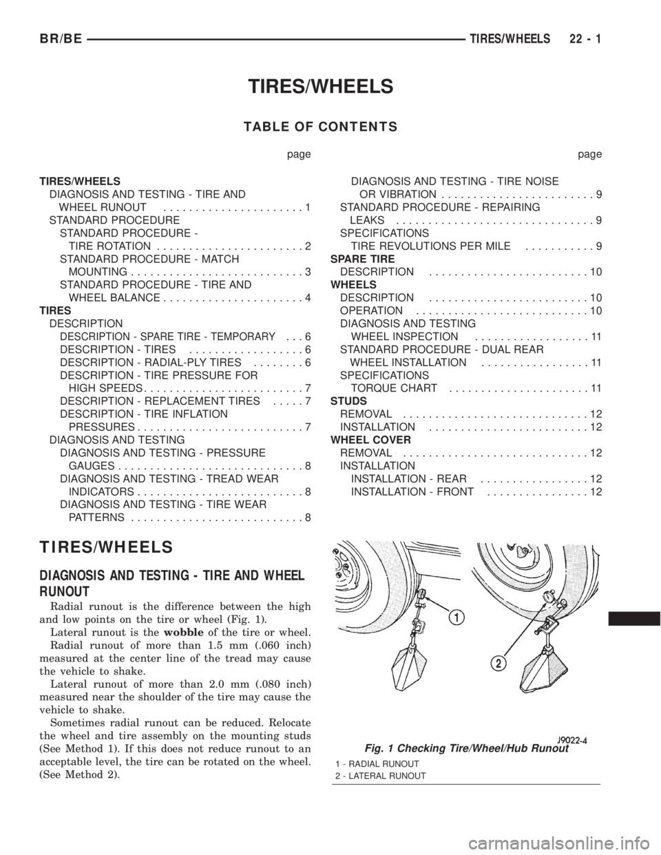
Radial runout is the difference between the high
and low points on the tire or wheel (Fig. 1).
Lateral runout is thewobbleof the tire or wheel.
Radial runout of more than 1.5 mm (.060 inch)
measured at the center line of the tread may cause
the vehicle to shake.
Lateral runout of more than 2.0 mm (.080 inch)
measured near the shoulder of the tire may cause the
vehicle to shake.
Sometimes radial runout can be reduced. Relocate
the wheel and tire assembly on the mounting studs
(See Method 1). If this does not reduce runout to an
acceptable level, the tire can be rotated on the wheel.
(See Method 2).
Fig. 1 Checking Tire/Wheel/Hub Runout
1 - RADIAL RUNOUT
2 - LATERAL RUNOUT
BR/BETIRES/WHEELS 22 - 1
Page 1961 of 2255
TIRES
DESCRIPTION
DESCRIPTION - SPARE TIRE - TEMPORARY
The temporary spare tire is designed for emer-
gency use only. The original tire should be repaired
or replaced at the first opportunity, then reinstalled.
Do not exceed speeds of 50 M.P.H. when using the
temporary spare tire. Refer to Owner's Manual for
complete details.
DESCRIPTION - TIRES
Tires are designed and engineered for each specific
vehicle. They provide the best overall performance
for normal operation. The ride and handling charac-
teristics match the vehicle's requirements. With
proper care they will give excellent reliability, trac-
tion, skid resistance, and tread life.
Driving habits have more effect on tire life than
any other factor. Careful drivers will obtain in most
cases, much greater mileage than severe use or care-
less drivers. A few of the driving habits which will
shorten the life of any tire are:
²Rapid acceleration
²Severe brake applications
²High speed driving
²Excessive speeds on turns
²Striking curbs and other obstacles
Radial-ply tires are more prone to irregular tread
wear. It is important to follow the tire rotation inter-
val shown in the section on Tire Rotation, (Refer to
22 - TIRES/WHEELS - STANDARD PROCEDURE).
This will help to achieve a greater tread life.
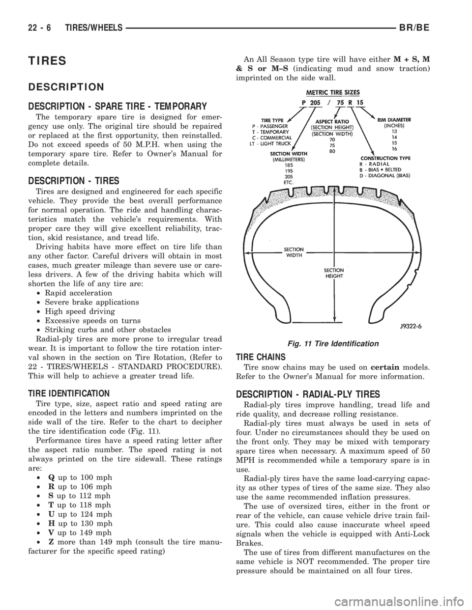
TIRE IDENTIFICATION
Tire type, size, aspect ratio and speed rating are
encoded in the letters and numbers imprinted on the
side wall of the tire. Refer to the chart to decipher
the tire identification code (Fig. 11).
Performance tires have a speed rating letter after
the aspect ratio number. The speed rating is not
always printed on the tire sidewall. These ratings
are:
²Qup to 100 mph
²Rup to 106 mph
²Sup to 112 mph
²Tup to 118 mph
²Uup to 124 mph
²Hup to 130 mph
²Vup to 149 mph
²Zmore than 149 mph (consult the tire manu-
facturer for the specific speed rating)An All Season type tire will have eitherM+S,M
&SorM±S(indicating mud and snow traction)
imprinted on the side wall.
TIRE CHAINS
Tire snow chains may be used oncertainmodels.
Refer to the Owner's Manual for more information.
DESCRIPTION - RADIAL-PLY TIRES
Radial-ply tires improve handling, tread life and
ride quality, and decrease rolling resistance.
Radial-ply tires must always be used in sets of
four. Under no circumstances should they be used on
the front only. They may be mixed with temporary
spare tires when necessary. A maximum speed of 50
MPH is recommended while a temporary spare is in
use.
Radial-ply tires have the same load-carrying capac-
ity as other types of tires of the same size. They also
use the same recommended inflation pressures.
The use of oversized tires, either in the front or
rear of the vehicle, can cause vehicle drive train fail-
ure. This could also cause inaccurate wheel speed
signals when the vehicle is equipped with Anti-Lock
Brakes.
The use of tires from different manufactures on the
same vehicle is NOT recommended. The proper tire
pressure should be maintained on all four tires.
Fig. 11 Tire Identification
22 - 6 TIRES/WHEELSBR/BE
Page 1962 of 2255
DESCRIPTION - TIRE PRESSURE FOR HIGH
SPEEDS
Where speed limits allow the vehicle to be driven
at high speeds, correct tire inflation pressure is very
important. For speeds up to and including 120 km/h
(75 mph), tires must be inflated to the pressures
shown on the tire placard. For continuous speeds in
excess of 120 km/h (75 mph), tires must be inflated
to the maximum pressure specified on the tire side-
wall.
Vehicles loaded to the maximum capacity should
not be driven at continuous speeds above 75 mph
(120 km/h).
For emergency vehicles that are driven at speeds
over 90 mph (144 km/h), special high speed tires
must be used. Consult tire manufacturer for correct
inflation pressure recommendations.
DESCRIPTION - REPLACEMENT TIRES
The original equipment tires provide a proper bal-
ance of many characteristics such as:
²Ride
²Noise
²Handling
²Durability
²Tread life
²Traction
²Rolling resistance
²Speed capability
It is recommended that tires equivalent to the orig-
inal equipment tires be used when replacement is
needed.
Failure to use equivalent replacement tires may
adversely affect the safety and handling of the vehi-
cle.
The use of oversize tires may cause interference
with vehicle components. Under extremes of suspen-
sion and steering travel, interference with vehicle
components may cause tire damage.
WARNING: FAILURE TO EQUIP THE VEHICLE WITH
TIRES HAVING ADEQUATE SPEED CAPABILITY
CAN RESULT IN SUDDEN TIRE FAILURE.
DESCRIPTION - TIRE INFLATION PRESSURES
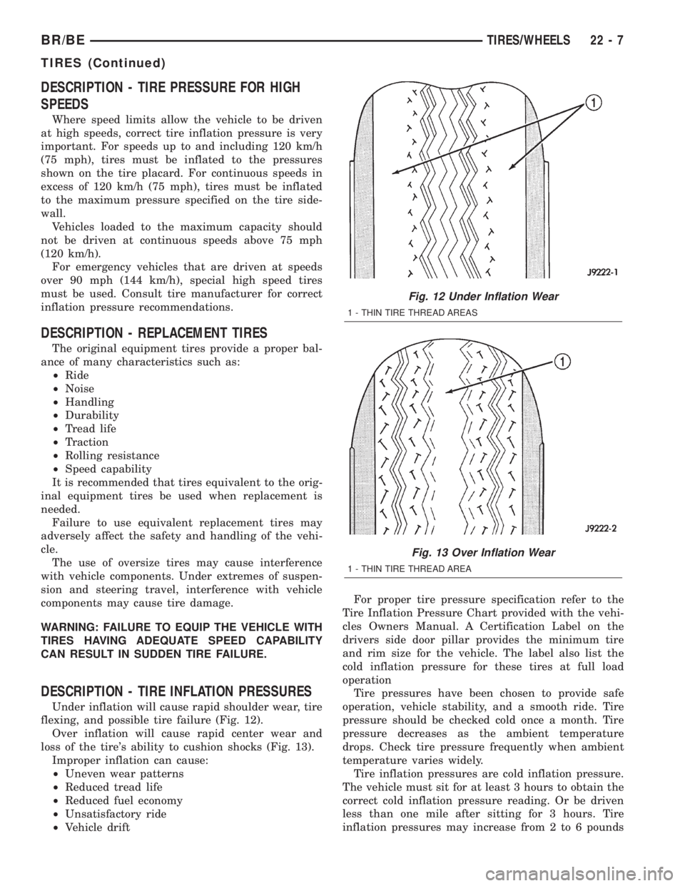
Under inflation will cause rapid shoulder wear, tire
flexing, and possible tire failure (Fig. 12).
Over inflation will cause rapid center wear and
loss of the tire's ability to cushion shocks (Fig. 13).
Improper inflation can cause:
²Uneven wear patterns
²Reduced tread life
²Reduced fuel economy
²Unsatisfactory ride
²Vehicle driftFor proper tire pressure specification refer to the
Tire Inflation Pressure Chart provided with the vehi-
cles Owners Manual. A Certification Label on the
drivers side door pillar provides the minimum tire
and rim size for the vehicle. The label also list the
cold inflation pressure for these tires at full load
operation
Tire pressures have been chosen to provide safe
operation, vehicle stability, and a smooth ride. Tire
pressure should be checked cold once a month. Tire
pressure decreases as the ambient temperature
drops. Check tire pressure frequently when ambient
temperature varies widely.
Tire inflation pressures are cold inflation pressure.
The vehicle must sit for at least 3 hours to obtain the
correct cold inflation pressure reading. Or be driven
less than one mile after sitting for 3 hours. Tire
inflation pressures may increase from 2 to 6 pounds
Fig. 12 Under Inflation Wear
1 - THIN TIRE THREAD AREAS
Fig. 13 Over Inflation Wear
1 - THIN TIRE THREAD AREA
BR/BETIRES/WHEELS 22 - 7
TIRES (Continued)
Page 1963 of 2255
per square inch (psi) during operation. Do not reduce
this normal pressure build-up.
WARNING: OVER OR UNDER INFLATED TIRES CAN
AFFECT VEHICLE HANDLING AND TREAD WEAR.
THIS MAY CAUSE THE TIRE TO FAIL SUDDENLY,
RESULTING IN LOSS OF VEHICLE CONTROL.
DIAGNOSIS AND TESTING
DIAGNOSIS AND TESTING - PRESSURE
GAUGES
A quality air pressure gauge is recommended to
check tire pressure. After checking the air pressure,
replace valve cap finger tight.
DIAGNOSIS AND TESTING - TREAD WEAR
INDICATORS
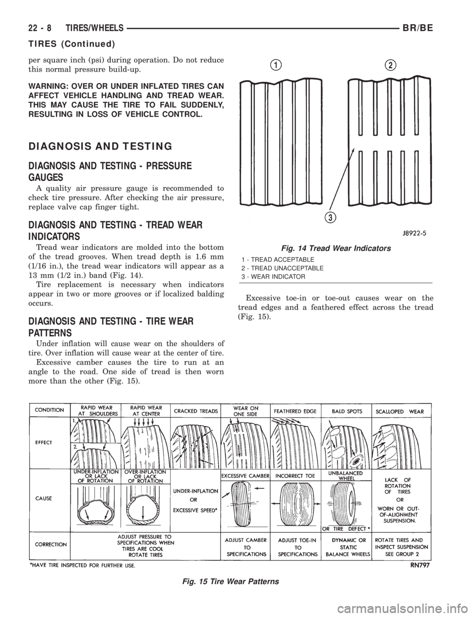
Tread wear indicators are molded into the bottom
of the tread grooves. When tread depth is 1.6 mm
(1/16 in.), the tread wear indicators will appear as a
13 mm (1/2 in.) band (Fig. 14).
Tire replacement is necessary when indicators
appear in two or more grooves or if localized balding
occurs.
DIAGNOSIS AND TESTING - TIRE WEAR
PATTERNS
Under inflation will cause wear on the shoulders of
tire. Over inflation will cause wear at the center of tire.
Excessive camber causes the tire to run at an
angle to the road. One side of tread is then worn
more than the other (Fig. 15).Excessive toe-in or toe-out causes wear on the
tread edges and a feathered effect across the tread
(Fig. 15).
Fig. 15 Tire Wear Patterns
Fig. 14 Tread Wear Indicators
1 - TREAD ACCEPTABLE
2 - TREAD UNACCEPTABLE
3 - WEAR INDICATOR
22 - 8 TIRES/WHEELSBR/BE
TIRES (Continued)
Page 2114 of 2255
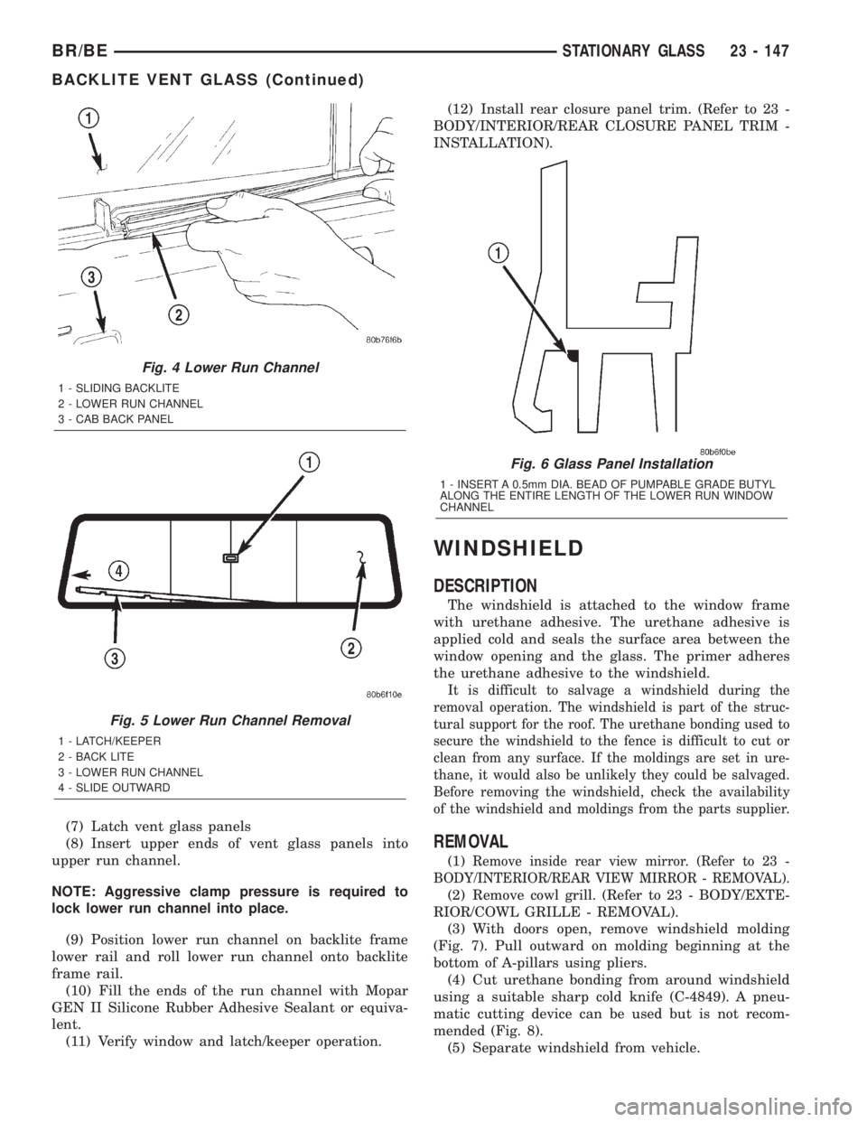
(7) Latch vent glass panels
(8) Insert upper ends of vent glass panels into
upper run channel.
NOTE: Aggressive clamp pressure is required to
lock lower run channel into place.
(9) Position lower run channel on backlite frame
lower rail and roll lower run channel onto backlite
frame rail.
(10) Fill the ends of the run channel with Mopar
GEN II Silicone Rubber Adhesive Sealant or equiva-
lent.
(11) Verify window and latch/keeper operation.(12) Install rear closure panel trim. (Refer to 23 -
BODY/INTERIOR/REAR CLOSURE PANEL TRIM -
INSTALLATION).
WINDSHIELD
DESCRIPTION
The windshield is attached to the window frame
with urethane adhesive. The urethane adhesive is
applied cold and seals the surface area between the
window opening and the glass. The primer adheres
the urethane adhesive to the windshield.
It is difficult to salvage a windshield during the
removal operation. The windshield is part of the struc-
tural support for the roof. The urethane bonding used to
secure the windshield to the fence is difficult to cut or
clean from any surface. If the moldings are set in ure-
thane, it would also be unlikely they could be salvaged.
Before removing the windshield, check the availability
of the windshield and moldings from the parts supplier.
REMOVAL
(1)Remove inside rear view mirror. (Refer to 23 -
BODY/INTERIOR/REAR VIEW MIRROR - REMOVAL).
(2) Remove cowl grill. (Refer to 23 - BODY/EXTE-
RIOR/COWL GRILLE - REMOVAL).
(3) With doors open, remove windshield molding
(Fig. 7). Pull outward on molding beginning at the
bottom of A-pillars using pliers.
(4) Cut urethane bonding from around windshield
using a suitable sharp cold knife (C-4849). A pneu-
matic cutting device can be used but is not recom-
mended (Fig. 8).
(5) Separate windshield from vehicle.
Fig. 4 Lower Run Channel
1 - SLIDING BACKLITE
2 - LOWER RUN CHANNEL
3 - CAB BACK PANEL
Fig. 5 Lower Run Channel Removal
1 - LATCH/KEEPER
2 - BACK LITE
3 - LOWER RUN CHANNEL
4 - SLIDE OUTWARD
Fig. 6 Glass Panel Installation
1 - INSERT A 0.5mm DIA. BEAD OF PUMPABLE GRADE BUTYL
ALONG THE ENTIRE LENGTH OF THE LOWER RUN WINDOW
CHANNEL
BR/BESTATIONARY GLASS 23 - 147
BACKLITE VENT GLASS (Continued)
Page 2162 of 2255
Any kinks or sharp bends in the refrigerant plumb-
ing will reduce the capacity of the entire air condi-
tioning system. Kinks and sharp bends reduce the
flow of refrigerant in the system. A good rule for the
flexible hose refrigerant lines is to keep the radius of
all bends at least ten times the diameter of the hose.
In addition, the flexible hose refrigerant lines should
be routed so they are at least 80 millimeters (3
inches) from the exhaust manifold.
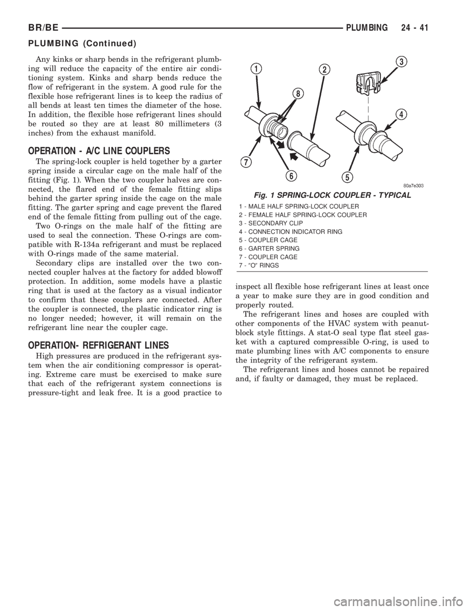
OPERATION - A/C LINE COUPLERS
The spring-lock coupler is held together by a garter
spring inside a circular cage on the male half of the
fitting (Fig. 1). When the two coupler halves are con-
nected, the flared end of the female fitting slips
behind the garter spring inside the cage on the male
fitting. The garter spring and cage prevent the flared
end of the female fitting from pulling out of the cage.
Two O-rings on the male half of the fitting are
used to seal the connection. These O-rings are com-
patible with R-134a refrigerant and must be replaced
with O-rings made of the same material.
Secondary clips are installed over the two con-
nected coupler halves at the factory for added blowoff
protection. In addition, some models have a plastic
ring that is used at the factory as a visual indicator
to confirm that these couplers are connected. After
the coupler is connected, the plastic indicator ring is
no longer needed; however, it will remain on the
refrigerant line near the coupler cage.
OPERATION- REFRIGERANT LINES
High pressures are produced in the refrigerant sys-
tem when the air conditioning compressor is operat-
ing. Extreme care must be exercised to make sure
that each of the refrigerant system connections is
pressure-tight and leak free. It is a good practice toinspect all flexible hose refrigerant lines at least once
a year to make sure they are in good condition and
properly routed.
The refrigerant lines and hoses are coupled with
other components of the HVAC system with peanut-
block style fittings. A stat-O seal type flat steel gas-
ket with a captured compressible O-ring, is used to
mate plumbing lines with A/C components to ensure
the integrity of the refrigerant system.
The refrigerant lines and hoses cannot be repaired
and, if faulty or damaged, they must be replaced.
Fig. 1 SPRING-LOCK COUPLER - TYPICAL
1 - MALE HALF SPRING-LOCK COUPLER
2 - FEMALE HALF SPRING-LOCK COUPLER
3 - SECONDARY CLIP
4 - CONNECTION INDICATOR RING
5 - COUPLER CAGE
6 - GARTER SPRING
7 - COUPLER CAGE
7-9O9RINGS
BR/BEPLUMBING 24 - 41
PLUMBING (Continued)