relay DODGE RAM 2002 Service Workshop Manual
[x] Cancel search | Manufacturer: DODGE, Model Year: 2002, Model line: RAM, Model: DODGE RAM 2002Pages: 2255, PDF Size: 62.07 MB
Page 461 of 2255
IGNITION COIL RESISTANCEÐ8.0L V-10
ENGINE
Primary Resistance: 0.53-0.65 Ohms. Test across the
primary connector. Refer to text for test procedures.
Secondary Resistance: 10.9-14.7K Ohms. Test
across the individual coil towers. Refer to text for test
procedures.
IGNITION TIMING
Ignition timing is not adjustable on any engine.
AUTOMATIC SHUT DOWN
RELAY
DESCRIPTION - PCM OUTPUT
The 5±pin, 12±volt, Automatic Shutdown (ASD)
relay is located in the Power Distribution Center
(PDC). Refer to label on PDC cover for relay location.
OPERATION
OPERATION - PCM OUTPUT
The ASD relay supplies battery voltage (12+ volts)
to the fuel injectors and ignition coil(s). With certain
emissions packages it also supplies 12±volts to the
oxygen sensor heating elements.
The ground circuit for the coil within the ASD
relay is controlled by the Powertrain Control Module
(PCM). The PCM operates the ASD relay by switch-
ing its ground circuit on and off.
The ASD relay will be shut±down, meaning the
12±volt power supply to the ASD relay will be de-ac-
tivated by the PCM if:
²the ignition key is left in the ON position. This
is if the engine has not been running for approxi-
mately 1.8 seconds.
²there is a crankshaft position sensor signal to
the PCM that is lower than pre-determined values.
OPERATION - ASD SENSE - PCM INPUT
A 12 volt signal at this input indicates to the PCM
that the ASD has been activated. The relay is used to
connect the oxygen sensor heater element, ignition
coil and fuel injectors to 12 volt + power supply.
This input is used only to sense that the ASD relay
is energized. If the Powertrain Control Module
(PCM) does not see 12 volts at this input when the
ASD should be activated, it will set a Diagnostic
Trouble Code (DTC).
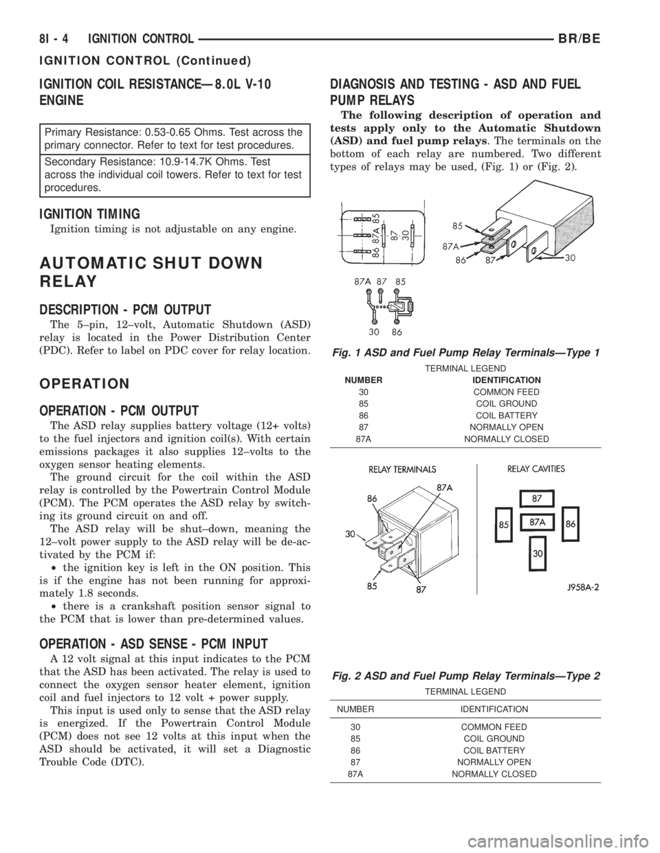
DIAGNOSIS AND TESTING - ASD AND FUEL
PUMP RELAYS
The following description of operation and
tests apply only to the Automatic Shutdown
(ASD) and fuel pump relays. The terminals on the
bottom of each relay are numbered. Two different
types of relays may be used, (Fig. 1) or (Fig. 2).
Fig. 1 ASD and Fuel Pump Relay TerminalsÐType 1
TERMINAL LEGEND
NUMBER IDENTIFICATION
30 COMMON FEED
85 COIL GROUND
86 COIL BATTERY
87 NORMALLY OPEN
87A NORMALLY CLOSED
Fig. 2 ASD and Fuel Pump Relay TerminalsÐType 2
TERMINAL LEGEND
NUMBER IDENTIFICATION
30 COMMON FEED
85 COIL GROUND
86 COIL BATTERY
87 NORMALLY OPEN
87A NORMALLY CLOSED
8I - 4 IGNITION CONTROLBR/BE
IGNITION CONTROL (Continued)
Page 462 of 2255
²Terminal number 30 is connected to battery volt-
age. For both the ASD and fuel pump relays, termi-
nal 30 is connected to battery voltage at all times.
²The PCM grounds the coil side of the relay
through terminal number 85.
²Terminal number 86 supplies voltage to the coil
side of the relay.
²When the PCM de-energizes the ASD and fuel
pump relays, terminal number 87A connects to termi-
nal 30. This is the Off position. In the off position,
voltage is not supplied to the rest of the circuit. Ter-
minal 87A is the center terminal on the relay.
²When the PCM energizes the ASD and fuel
pump relays, terminal 87 connects to terminal 30.
This is the On position. Terminal 87 supplies voltage
to the rest of the circuit.
The following procedure applies to the ASD and
fuel pump relays.
(1) Remove relay from connector before testing.
(2) With the relay removed from the vehicle, use
an ohmmeter to check the resistance between termi-
nals 85 and 86. The resistance should be 75 ohms +/-
5 ohms.
(3) Connect the ohmmeter between terminals 30
and 87A. The ohmmeter should show continuity
between terminals 30 and 87A.
(4) Connect the ohmmeter between terminals 87
and 30. The ohmmeter should not show continuity at
this time.
(5) Connect one end of a jumper wire (16 gauge or
smaller) to relay terminal 85. Connect the other end
of the jumper wire to the ground side of a 12 volt
power source.
(6) Connect one end of another jumper wire (16
gauge or smaller) to the power side of the 12 volt
power source.Do not attach the other end of the
jumper wire to the relay at this time.
WARNING: DO NOT ALLOW OHMMETER TO CON-
TACT TERMINALS 85 OR 86 DURING THIS TEST.
DAMAGE TO OHMMETER MAY RESULT.
(7) Attach the other end of the jumper wire to
relay terminal 86. This activates the relay. The ohm-
meter should now show continuity between relay ter-
minals 87 and 30. The ohmmeter should not show
continuity between relay terminals 87A and 30.
(8) Disconnect jumper wires.(9) Replace the relay if it did not pass the continu-
ity and resistance tests. If the relay passed the tests,
it operates properly. Check the remainder of the ASD
and fuel pump relay circuits. Refer to 8, Wiring Dia-
grams.
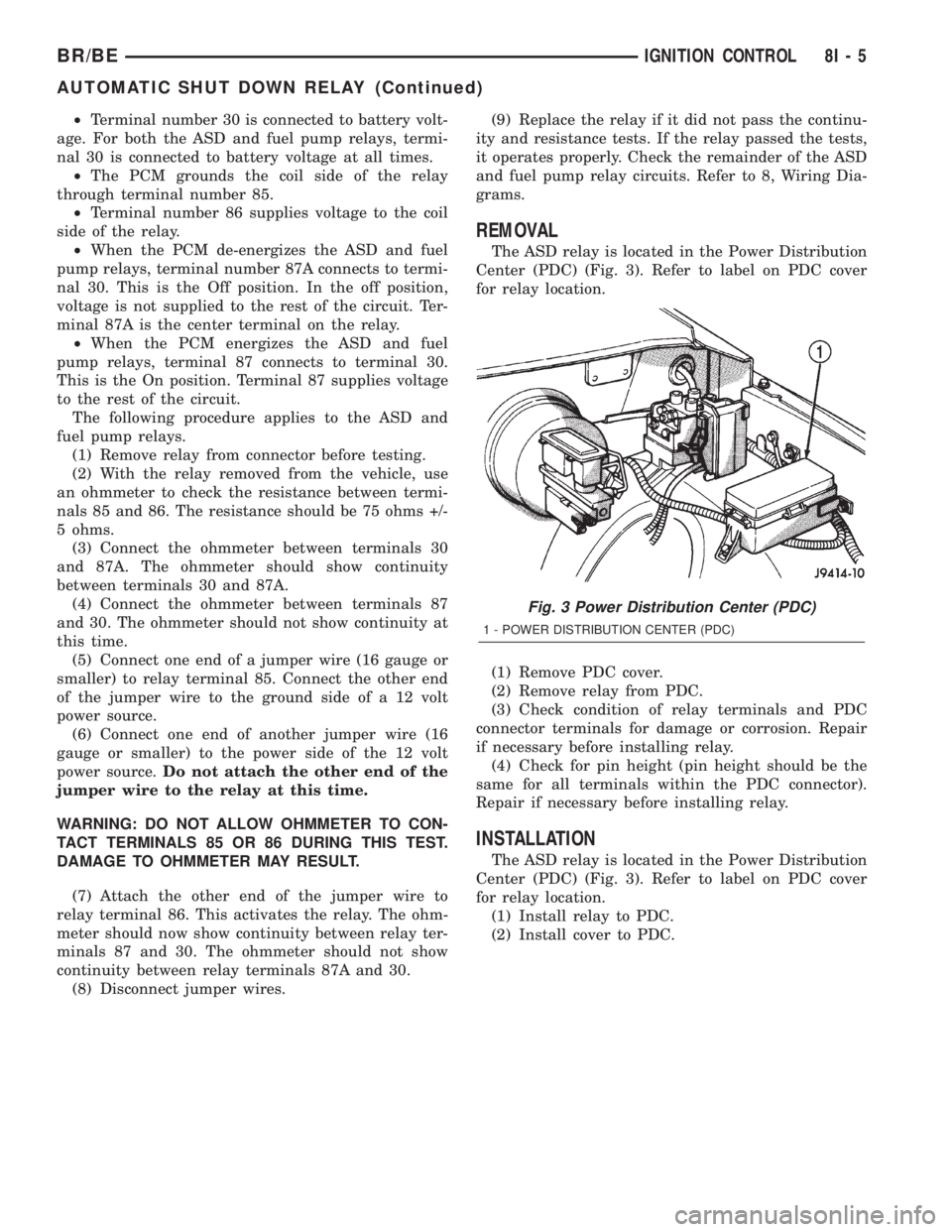
REMOVAL
The ASD relay is located in the Power Distribution
Center (PDC) (Fig. 3). Refer to label on PDC cover
for relay location.
(1) Remove PDC cover.
(2) Remove relay from PDC.
(3) Check condition of relay terminals and PDC
connector terminals for damage or corrosion. Repair
if necessary before installing relay.
(4) Check for pin height (pin height should be the
same for all terminals within the PDC connector).
Repair if necessary before installing relay.
INSTALLATION
The ASD relay is located in the Power Distribution
Center (PDC) (Fig. 3). Refer to label on PDC cover
for relay location.
(1) Install relay to PDC.
(2) Install cover to PDC.
Fig. 3 Power Distribution Center (PDC)
1 - POWER DISTRIBUTION CENTER (PDC)
BR/BEIGNITION CONTROL 8I - 5
AUTOMATIC SHUT DOWN RELAY (Continued)
Page 472 of 2255
IGNITION COIL
DESCRIPTION
DESCRIPTION - 5.9L
A single ignition coil is used. The coil is not oil
filled. The coil windings are embedded in an epoxy
compound. This provides heat and vibration resis-
tance that allows the coil to be mounted on the
engine.
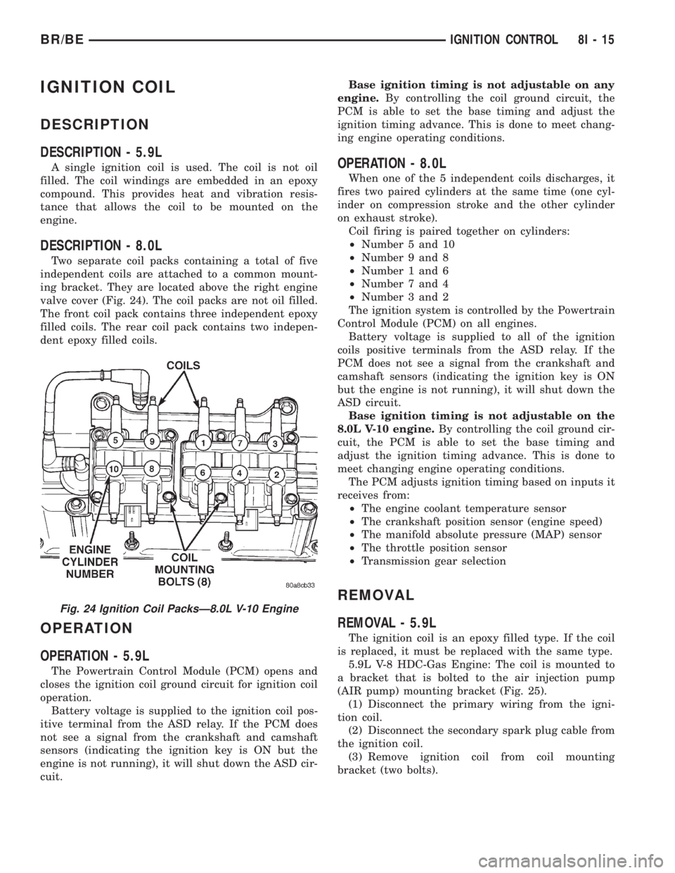
DESCRIPTION - 8.0L
Two separate coil packs containing a total of five
independent coils are attached to a common mount-
ing bracket. They are located above the right engine
valve cover (Fig. 24). The coil packs are not oil filled.
The front coil pack contains three independent epoxy
filled coils. The rear coil pack contains two indepen-
dent epoxy filled coils.
OPERATION
OPERATION - 5.9L
The Powertrain Control Module (PCM) opens and
closes the ignition coil ground circuit for ignition coil
operation.
Battery voltage is supplied to the ignition coil pos-
itive terminal from the ASD relay. If the PCM does
not see a signal from the crankshaft and camshaft
sensors (indicating the ignition key is ON but the
engine is not running), it will shut down the ASD cir-
cuit.Base ignition timing is not adjustable on any
engine.By controlling the coil ground circuit, the
PCM is able to set the base timing and adjust the
ignition timing advance. This is done to meet chang-
ing engine operating conditions.
OPERATION - 8.0L
When one of the 5 independent coils discharges, it
fires two paired cylinders at the same time (one cyl-
inder on compression stroke and the other cylinder
on exhaust stroke).
Coil firing is paired together on cylinders:
²Number 5 and 10
²Number 9 and 8
²Number 1 and 6
²Number 7 and 4
²Number 3 and 2
The ignition system is controlled by the Powertrain
Control Module (PCM) on all engines.
Battery voltage is supplied to all of the ignition
coils positive terminals from the ASD relay. If the
PCM does not see a signal from the crankshaft and
camshaft sensors (indicating the ignition key is ON
but the engine is not running), it will shut down the
ASD circuit.
Base ignition timing is not adjustable on the
8.0L V-10 engine.By controlling the coil ground cir-
cuit, the PCM is able to set the base timing and
adjust the ignition timing advance. This is done to
meet changing engine operating conditions.
The PCM adjusts ignition timing based on inputs it
receives from:
²The engine coolant temperature sensor
²The crankshaft position sensor (engine speed)
²The manifold absolute pressure (MAP) sensor
²The throttle position sensor
²Transmission gear selection
REMOVAL
REMOVAL - 5.9L
The ignition coil is an epoxy filled type. If the coil
is replaced, it must be replaced with the same type.
5.9L V-8 HDC-Gas Engine: The coil is mounted to
a bracket that is bolted to the air injection pump
(AIR pump) mounting bracket (Fig. 25).
(1) Disconnect the primary wiring from the igni-
tion coil.
(2) Disconnect the secondary spark plug cable from
the ignition coil.
(3) Remove ignition coil from coil mounting
bracket (two bolts).
Fig. 24 Ignition Coil PacksÐ8.0L V-10 Engine
BR/BEIGNITION CONTROL 8I - 15
Page 516 of 2255
LAMPS
TABLE OF CONTENTS
page page
LAMPS/LIGHTING - EXTERIOR............... 1LAMPS/LIGHTING - INTERIOR............... 33
LAMPS/LIGHTING - EXTERIOR
TABLE OF CONTENTS
page page
LAMPS/LIGHTING - EXTERIOR
DESCRIPTION - TURN SIGNAL & HAZARD
WARNING SYSTEM.....................2
OPERATION - TURN SIGNAL & HAZARD
WARNING SYSTEM.....................2
DIAGNOSIS AND TESTING - TURN SIGNAL &
HAZARD WARNING SYSTEM.............3
SPECIFICATIONS
EXTERIOR LAMPS.....................4
SPECIAL TOOLS
HEADLAMP ALIGNMENT................4
BRAKE LAMP SWITCH
DESCRIPTION..........................4
OPERATION............................4
DIAGNOSIS AND TESTING - BRAKE LAMP
SWITCH.............................5
REMOVAL.............................5
INSTALLATION..........................6
CENTER HIGH MOUNTED STOP LAMP
REMOVAL.............................6
INSTALLATION..........................6
CENTER HIGH MOUNTED STOP LAMP UNIT
REMOVAL.............................6
INSTALLATION..........................6
CLEARANCE LAMP
REMOVAL.............................7
INSTALLATION..........................7
COMBINATION FLASHER
DESCRIPTION..........................7
OPERATION............................7
REMOVAL.............................8
INSTALLATION..........................9
DAYTIME RUNNING LAMP MODULE
DESCRIPTION..........................9
OPERATION............................9
REMOVAL.............................9
INSTALLATION..........................9FOG LAMP
DIAGNOSIS AND TESTING - FOG LAMP.....10
REMOVAL.............................11
INSTALLATION.........................11
FOG LAMP UNIT
REMOVAL.............................12
INSTALLATION.........................12
ADJUSTMENTS........................13
HEADLAMP
DESCRIPTION.........................13
OPERATION...........................13
DIAGNOSIS AND TESTING - HEADLAMP.....14
REMOVAL.............................16
INSTALLATION.........................16
HEADLAMP RELAY
DESCRIPTION.........................17
OPERATION...........................17
DIAGNOSIS AND TESTING - HEADLAMP
RELAY..............................17
REMOVAL.............................18
INSTALLATION.........................18
HEADLAMP SWITCH
DESCRIPTION.........................18
OPERATION...........................18
DIAGNOSIS AND TESTING - HEADLAMP
SWITCH............................19
REMOVAL.............................19
INSTALLATION.........................20
HEADLAMP UNIT
REMOVAL.............................20
INSTALLATION.........................21
ADJUSTMENTS........................21
LICENSE PLATE LAMP
REMOVAL.............................22
INSTALLATION.........................22
LICENSE PLATE LAMP UNIT
REMOVAL.............................22
BR/BELAMPS 8L - 1
Page 522 of 2255
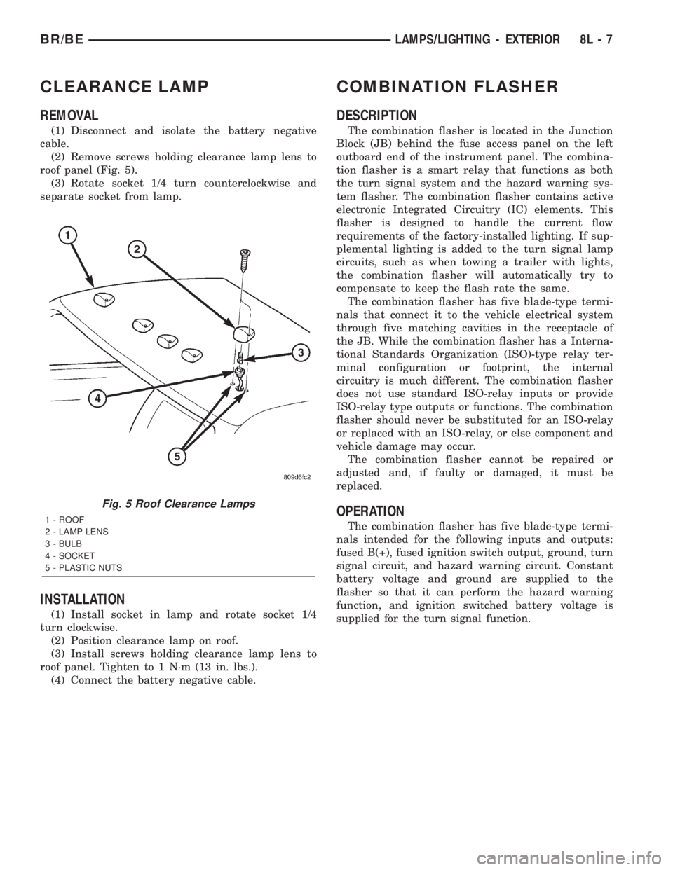
CLEARANCE LAMP
REMOVAL
(1) Disconnect and isolate the battery negative
cable.
(2) Remove screws holding clearance lamp lens to
roof panel (Fig. 5).
(3) Rotate socket 1/4 turn counterclockwise and
separate socket from lamp.
INSTALLATION
(1) Install socket in lamp and rotate socket 1/4
turn clockwise.
(2) Position clearance lamp on roof.
(3) Install screws holding clearance lamp lens to
roof panel. Tighten to 1 N´m (13 in. lbs.).
(4) Connect the battery negative cable.
COMBINATION FLASHER
DESCRIPTION
The combination flasher is located in the Junction
Block (JB) behind the fuse access panel on the left
outboard end of the instrument panel. The combina-
tion flasher is a smart relay that functions as both
the turn signal system and the hazard warning sys-
tem flasher. The combination flasher contains active
electronic Integrated Circuitry (IC) elements. This
flasher is designed to handle the current flow
requirements of the factory-installed lighting. If sup-
plemental lighting is added to the turn signal lamp
circuits, such as when towing a trailer with lights,
the combination flasher will automatically try to
compensate to keep the flash rate the same.
The combination flasher has five blade-type termi-
nals that connect it to the vehicle electrical system
through five matching cavities in the receptacle of
the JB. While the combination flasher has a Interna-
tional Standards Organization (ISO)-type relay ter-
minal configuration or footprint, the internal
circuitry is much different. The combination flasher
does not use standard ISO-relay inputs or provide
ISO-relay type outputs or functions. The combination
flasher should never be substituted for an ISO-relay
or replaced with an ISO-relay, or else component and
vehicle damage may occur.
The combination flasher cannot be repaired or
adjusted and, if faulty or damaged, it must be
replaced.
OPERATION
The combination flasher has five blade-type termi-
nals intended for the following inputs and outputs:
fused B(+), fused ignition switch output, ground, turn
signal circuit, and hazard warning circuit. Constant
battery voltage and ground are supplied to the
flasher so that it can perform the hazard warning
function, and ignition switched battery voltage is
supplied for the turn signal function.
Fig. 5 Roof Clearance Lamps
1 - ROOF
2 - LAMP LENS
3 - BULB
4 - SOCKET
5 - PLASTIC NUTS
BR/BELAMPS/LIGHTING - EXTERIOR 8L - 7
Page 530 of 2255
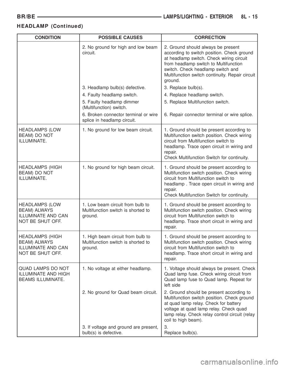
CONDITION POSSIBLE CAUSES CORRECTION
2. No ground for high and low beam
circuit.2. Ground should always be present
according to switch position. Check ground
at headlamp switch. Check wiring circuit
from headlamp switch to Multifunction
switch. Check headlamp switch and
Multifunction switch continuity. Repair circuit
ground.
3. Headlamp bulb(s) defective. 3. Replace bulb(s).
4. Faulty headlamp switch. 4. Replace headlamp switch.
5. Faulty headlamp dimmer
(Multifunction) switch.5. Replace Multifunction switch.
6. Broken connector terminal or wire
splice in headlamp circuit.6. Repair connector terminal or wire splice.
HEADLAMPS (LOW
BEAM) DO NOT
ILLUMINATE.1. No ground for low beam circuit. 1. Ground should be present according to
Multifunction switch position. Check wiring
circuit from Multifunction switch to
headlamp. Trace open circuit in wiring and
repair.
Check Multifunction Switch for continuity.
HEADLAMPS (HIGH
BEAM) DO NOT
ILLUMINATE.1. No ground for high beam circuit. 1. Ground should be present according to
Multifunction switch position. Check wiring
circuit from Multifunction switch to
headlamp . Trace open circuit in wiring and
repair.
Check Multifunction Switch for continuity.
HEADLAMPS (LOW
BEAM) ALWAYS
ILLUMINATE AND CAN
NOT BE SHUT OFF.1. Low beam circuit from bulb to
Multifunction switch is shorted to
ground.1. Ground should be present according to
Multifunction switch position. Check wiring
circuit from Multifunction switch to
headlamp. Trace short circuit in wiring and
repair.
HEADLAMPS (HIGH
BEAM) ALWAYS
ILLUMINATE AND CAN
NOT BE SHUT OFF.1. High beam circuit from bulb to
Multifunction switch is shorted to
ground.1. Ground should be present according to
Multifunction switch position. Check wiring
circuit from Multifunction switch to
headlamp. Trace short circuit in wiring and
repair.
QUAD LAMPS DO NOT
ILLUMINATE AND HIGH
BEAMS ILLUMINATE.1. No voltage at either headlamp. 1. Voltage should always be present. Check
Quad lamp fuse. Check wiring circuit from
Quad lamp fuse to Quad lamp. Repeat for
left side
2. No ground for Quad beam circuit. 2. Ground should be present according to
Multifunction switch position. Check ground
at quad lamp relay. Check for battery
voltage at quad lamp relay. Check quad
lamp relay. Check relay control circuit (relay
coil to high beam).
3. If voltage and ground are present,
bulb(s) is defective.3.
Replace bulb(s).
BR/BELAMPS/LIGHTING - EXTERIOR 8L - 15
HEADLAMP (Continued)
Page 532 of 2255
HEADLAMP RELAY
DESCRIPTION
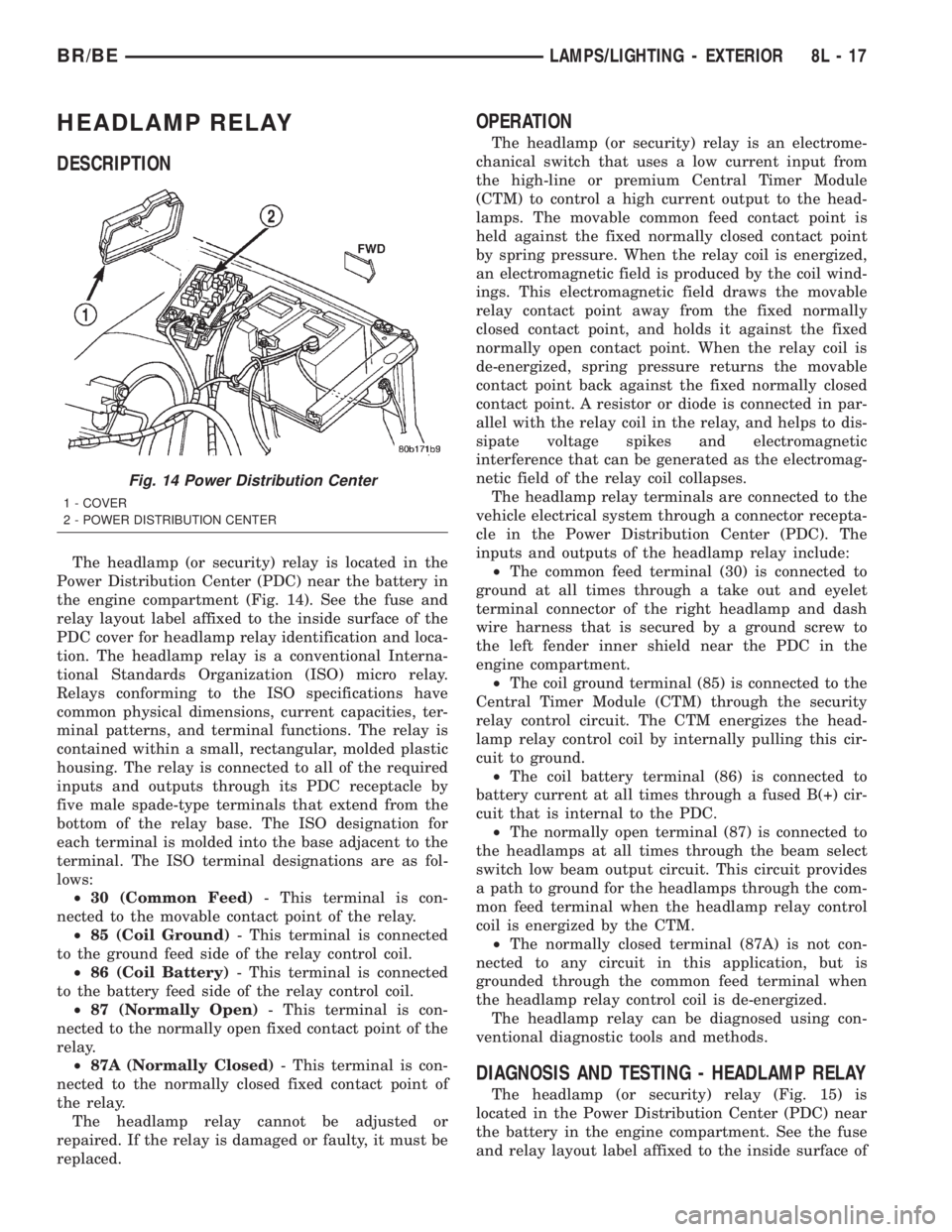
The headlamp (or security) relay is located in the
Power Distribution Center (PDC) near the battery in
the engine compartment (Fig. 14). See the fuse and
relay layout label affixed to the inside surface of the
PDC cover for headlamp relay identification and loca-
tion. The headlamp relay is a conventional Interna-
tional Standards Organization (ISO) micro relay.
Relays conforming to the ISO specifications have
common physical dimensions, current capacities, ter-
minal patterns, and terminal functions. The relay is
contained within a small, rectangular, molded plastic
housing. The relay is connected to all of the required
inputs and outputs through its PDC receptacle by
five male spade-type terminals that extend from the
bottom of the relay base. The ISO designation for
each terminal is molded into the base adjacent to the
terminal. The ISO terminal designations are as fol-
lows:
²30 (Common Feed)- This terminal is con-
nected to the movable contact point of the relay.
²85 (Coil Ground)- This terminal is connected
to the ground feed side of the relay control coil.
²86 (Coil Battery)- This terminal is connected
to the battery feed side of the relay control coil.
²87 (Normally Open)- This terminal is con-
nected to the normally open fixed contact point of the
relay.
²87A (Normally Closed)- This terminal is con-
nected to the normally closed fixed contact point of
the relay.
The headlamp relay cannot be adjusted or
repaired. If the relay is damaged or faulty, it must be
replaced.
OPERATION
The headlamp (or security) relay is an electrome-
chanical switch that uses a low current input from
the high-line or premium Central Timer Module
(CTM) to control a high current output to the head-
lamps. The movable common feed contact point is
held against the fixed normally closed contact point
by spring pressure. When the relay coil is energized,
an electromagnetic field is produced by the coil wind-
ings. This electromagnetic field draws the movable
relay contact point away from the fixed normally
closed contact point, and holds it against the fixed
normally open contact point. When the relay coil is
de-energized, spring pressure returns the movable
contact point back against the fixed normally closed
contact point. A resistor or diode is connected in par-
allel with the relay coil in the relay, and helps to dis-
sipate voltage spikes and electromagnetic
interference that can be generated as the electromag-
netic field of the relay coil collapses.
The headlamp relay terminals are connected to the
vehicle electrical system through a connector recepta-
cle in the Power Distribution Center (PDC). The
inputs and outputs of the headlamp relay include:
²The common feed terminal (30) is connected to
ground at all times through a take out and eyelet
terminal connector of the right headlamp and dash
wire harness that is secured by a ground screw to
the left fender inner shield near the PDC in the
engine compartment.
²The coil ground terminal (85) is connected to the
Central Timer Module (CTM) through the security
relay control circuit. The CTM energizes the head-
lamp relay control coil by internally pulling this cir-
cuit to ground.
²The coil battery terminal (86) is connected to
battery current at all times through a fused B(+) cir-
cuit that is internal to the PDC.
²The normally open terminal (87) is connected to
the headlamps at all times through the beam select
switch low beam output circuit. This circuit provides
a path to ground for the headlamps through the com-
mon feed terminal when the headlamp relay control
coil is energized by the CTM.
²The normally closed terminal (87A) is not con-
nected to any circuit in this application, but is
grounded through the common feed terminal when
the headlamp relay control coil is de-energized.
The headlamp relay can be diagnosed using con-
ventional diagnostic tools and methods.
DIAGNOSIS AND TESTING - HEADLAMP RELAY
The headlamp (or security) relay (Fig. 15) is
located in the Power Distribution Center (PDC) near
the battery in the engine compartment. See the fuse
and relay layout label affixed to the inside surface of
Fig. 14 Power Distribution Center
1 - COVER
2 - POWER DISTRIBUTION CENTER
BR/BELAMPS/LIGHTING - EXTERIOR 8L - 17
Page 533 of 2255
the PDC cover for headlamp relay identification and
location. Refer to the appropriate wiring information.
The wiring information includes wiring diagrams,
proper wire and connector repair procedures, details
of wire harness routing and retention, connector pin-
out information and location views for the various
wire harness connectors, splices and grounds.
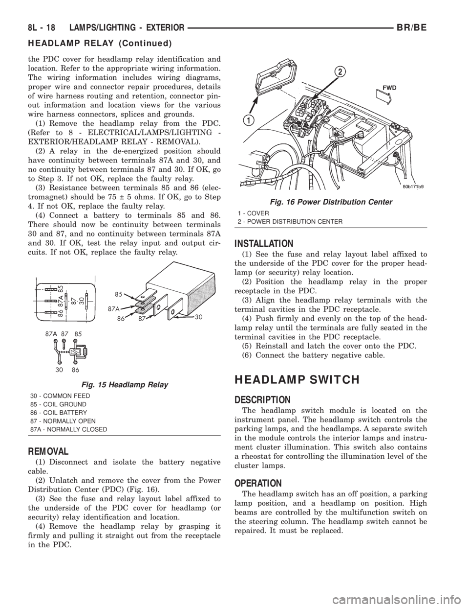
(1) Remove the headlamp relay from the PDC.
(Refer to 8 - ELECTRICAL/LAMPS/LIGHTING -
EXTERIOR/HEADLAMP RELAY - REMOVAL).
(2) A relay in the de-energized position should
have continuity between terminals 87A and 30, and
no continuity between terminals 87 and 30. If OK, go
to Step 3. If not OK, replace the faulty relay.
(3) Resistance between terminals 85 and 86 (elec-
tromagnet) should be 75 5 ohms. If OK, go to Step
4. If not OK, replace the faulty relay.
(4) Connect a battery to terminals 85 and 86.
There should now be continuity between terminals
30 and 87, and no continuity between terminals 87A
and 30. If OK, test the relay input and output cir-
cuits. If not OK, replace the faulty relay.
REMOVAL
(1) Disconnect and isolate the battery negative
cable.
(2) Unlatch and remove the cover from the Power
Distribution Center (PDC) (Fig. 16).
(3) See the fuse and relay layout label affixed to
the underside of the PDC cover for headlamp (or
security) relay identification and location.
(4) Remove the headlamp relay by grasping it
firmly and pulling it straight out from the receptacle
in the PDC.
INSTALLATION
(1) See the fuse and relay layout label affixed to
the underside of the PDC cover for the proper head-
lamp (or security) relay location.
(2) Position the headlamp relay in the proper
receptacle in the PDC.
(3) Align the headlamp relay terminals with the
terminal cavities in the PDC receptacle.
(4) Push firmly and evenly on the top of the head-
lamp relay until the terminals are fully seated in the
terminal cavities in the PDC receptacle.
(5) Reinstall and latch the cover onto the PDC.
(6) Connect the battery negative cable.
HEADLAMP SWITCH
DESCRIPTION
The headlamp switch module is located on the
instrument panel. The headlamp switch controls the
parking lamps, and the headlamps. A separate switch
in the module controls the interior lamps and instru-
ment cluster illumination. This switch also contains
a rheostat for controlling the illumination level of the
cluster lamps.
OPERATION
The headlamp switch has an off position, a parking
lamp position, and a headlamp on position. High
beams are controlled by the multifunction switch on
the steering column. The headlamp switch cannot be
repaired. It must be replaced.
Fig. 15 Headlamp Relay
30 - COMMON FEED
85 - COIL GROUND
86 - COIL BATTERY
87 - NORMALLY OPEN
87A - NORMALLY CLOSED
Fig. 16 Power Distribution Center
1 - COVER
2 - POWER DISTRIBUTION CENTER
8L - 18 LAMPS/LIGHTING - EXTERIORBR/BE
HEADLAMP RELAY (Continued)
Page 539 of 2255
²Continuous Wipe Modes- The control knob of
the multi-function switch provides two continuous
wipe switch positions, low speed or high speed.
²Hazard Warning Control- The internal cir-
cuitry and hardware of the multi-function switch pro-
vide detent switching for activation and deactivation
of the hazard warning system.
²Headlamp Beam Selection- The internal cir-
cuitry and hardware of the multi-function switch pro-
vide detent switching for selection of the headlamp
high or low beams.
²Headlamp Optical Horn- The internal cir-
cuitry and hardware of the multi-function switch
includes momentary switching of the headlamp high
beam circuits to provide an optical horn feature
(sometimes referred to as flash-to-pass), which allows
the vehicle operator to momentarily flash the head-
lamp high beams as an optical signalling device.
²Intermittent Wipe Mode- The control knob of
the multi-function switch provides an intermittent
wipe mode with multiple delay interval positions.
²Turn Signal Control- The internal circuitry
and hardware of the multi-function switch provide
both momentary non-detent switching and detent
switching with automatic cancellation for both the
left and right turn signals.
²Washer Mode- A button on the end of the con-
trol stalk of the multi-function switch provides
washer system operation when the button is
depressed towards the steering column.
The multi-function switch cannot be adjusted or
repaired. If any function of the switch is faulty, or if
the switch is damaged, the entire switch unit must
be replaced.
OPERATION
The multi-function switch uses conventionally
switched outputs and a variable resistor to control
the many functions and features it provides using
hard wired circuitry. The switch is grounded at all
times through a single wire take out with an eyelet
terminal connector of the instrument panel wire har-
ness that is secured by a nut to a ground stud
located on the instrument panel armature, just above
and to the left of the glove box opening. When the
ignition switch is in the Accessory or On positions,
battery current from a fuse in the Junction Block
(JB) is provided through a fused ignition switch out-
put (run-acc) circuit. Following are descriptions of
how the multi-function switch operates to control the
many functions and features it provides:²Continuous Wipe Modes- When the control
knob of the multi-function switch is rotated to the
High or Low positions, the circuitry within the
switch provides a battery current output directly to
the high or low speed brush of the wiper motor.
When the control knob is in the Off position, the cir-
cuitry within the switch connects the output of the
wiper motor park switch to the low speed brush of
the wiper motor.
²Hazard Warning Control- The hazard warn-
ing push button is pushed down to unlatch the
switch and activate the hazard warning system, and
pushed down again to latch the switch and turn the
system off. When the hazard warning switch is
latched (hazard warning off), the push button will be
in a lowered position on the top of the steering col-
umn shroud; and, when the hazard warning switch is
unlatched (hazard warning on), the push button will
be in a raised position. The multi-function switch
hazard warning circuitry simultaneously provides a
signal to the hazard warning sense of the combina-
tion flasher to activate or deactivate the flasher out-
put, and directs the output of the flasher to the
hazard warning lamps.
²Headlamp Beam Selection- The multi-func-
tion switch control stalk is pulled towards the steer-
ing wheel past a detent, then released to actuate the
headlamp beam selection switch. Each time the con-
trol stalk is actuated in this manner, the opposite
headlamp mode from what is currently selected will
be activated. The internal circuitry of the headlamp
beam selection switch directs the output of the head-
lamp switch through hard wired circuitry to activate
the selected headlamp beam.
²Headlamp Optical Horn- The left multi-func-
tion switch control stalk is pulled towards the steer-
ing wheel to just before a detent, to momentarily
activate the headlamp high beams. The high beams
will remain illuminated until the control stalk is
released. The internal circuitry of the headlamp
beam selection switch provides a momentary ground
path to the headlamp high beams.
²Intermittent Wipe Mode- When the multi-
function switch control knob is rotated to the Delay
position, the circuitry within the switch connects the
output of the wiper motor relay to the low speed
brush of the wiper motor and provides a battery cur-
rent signal to the Central Timer Module (CTM). If
the Delay mode is selected, the control knob can then
be rotated to multiple minor detent positions, which
actuates a variable resistor within the switch and
provides a hard wired output to the CTM that sig-
nals the desired delay interval for the intermittent
wiper feature.
8L - 24 LAMPS/LIGHTING - EXTERIORBR/BE
MULTI-FUNCTION SWITCH (Continued)
Page 570 of 2255
optional horn chirp durations (twenty or forty milli-
seconds) can also be selected.
²Illuminated Entry- This feature turns on the
courtesy lamps in the vehicle for a timed interval
(about thirty seconds) each time a valid Unlock sig-
nal has been received from the RKE transmitter.
²Panic Mode- This feature allows the vehicle
operator to cause the vehicle horn to pulse, the head-
lights to flash, and the courtesy lamps to illuminate
for about three minutes by depressing a Panic button
on the RKE transmitter. Pressing the Panic button a
second time will cancel the Panic mode. A vehicle
speed of about 24 kilometers-per-hour (15 miles-per-
hour) will also cancel the panic mode.
OPERATION
OPERATION - POWER LOCKS
All versions of the power lock system allow both
doors to be locked or unlocked electrically by operat-
ing the power lock switch on either front door trim
panel. On vehicles that are also equipped with the
optional Remote Keyless Entry (RKE) system, both
doors may also be locked or unlocked using a key in
either front door lock cylinder, or by using the RKE
transmitter. On vehicles with the RKE system, if cer-
tain features have been electronically enabled, the
locks may also be operated automatically by the
high-line or premium Central Timer Module (CTM)
based upon various other inputs. Those features and
their inputs are:
²Automatic Door Lock- If enabled, the high-
line/premium CTM will automatically lock the doors
when it receives a message from the Powertrain Con-
trol Module (PCM) indicating that the vehicle speed
is about 24 kilometers-per-hour (15 miles-per-hour)
or greater. The CTM also monitors the door ajar
switches, and will not activate the automatic door
lock feature until both doors have been closed for at
least five seconds. If this feature is enabled and a
door is opened after the vehicle is moving, the CTM
will also lock the doors five seconds after both doors
are closed.
²Central Locking- Vehicles equipped with a
high-line/premium CTM also have a resistor-multi-
plexed door cylinder lock switch mounted to the back
of the door lock cylinder within each front door. The
CTM continually monitors the input from these
switches to provide the central locking/unlocking fea-
ture. The CTM will automatically lock or unlock both
front doors when either front door is locked or
unlocked using a key.
²Door Lock Inhibit- The high-line/premium
CTM receives inputs from the key-in ignition switch,the headlamp switch, and the door ajar switches. The
logic within the CTM allows it to monitor these
inputs to provide a door lock inhibit feature. The
door lock inhibit feature prevents the power lock sys-
tem from being energized with a power lock switch
input if the driver door is open with the headlamps
on or the key still in the ignition switch. However,
the locks can still be operated with the manual door
lock button or with a key in the door lock cylinder,
and the power locks will still operate using the RKE
transmitter while the driver door is open with the
headlamps on or a key in the ignition.
²Enhanced Accident Response- If enabled,
the high-line/premium CTM provides an enhanced
accident response feature. This feature uses elec-
tronic message inputs received by the CTM from the
Airbag Control Module (ACM) to determine when an
airbag has been deployed. The CTM also monitors
the state of the power lock system and the vehicle
speed messages from the PCM in order to provide
this feature. If the airbag has been deployed and the
vehicle has stopped moving, the CTM will automati-
cally unlock the doors, prevent the doors from being
locked, and turn on the courtesy lamps inside the
vehicle. Of course, these responses are dependent
upon a functional battery and electrical circuitry fol-
lowing the impact.
All versions of the power lock system operate on
battery current received through a fused B(+) circuit
from a fuse in the Junction Block (JB) so that the
system remains functional, regardless of the ignition
switch position. Also, in both versions of the power
lock system, each power lock switch receives battery
current independent of the other. In vehicles with the
base version of the power lock system, the driver side
power lock switch receives ground through the body
wire harness. A single wire take out of the body wire
harness with an eyelet terminal connector is secured
by a ground screw to the lower left B-pillar (regular
cab, extended cab) or lower left quarter inner panel
(quad cab). The passenger side power lock switch
receives ground through the driver side power lock
switch in the base version of the power lock system.
The base version power lock switches direct the
appropriate battery current and ground feeds to the
power lock motors. In the power lock system for vehi-
cles with the RKE system, the power lock switches
direct a battery current Lock or Unlock request sig-
nal to the high-line or premium CTM, and the CTM
energizes internal relays to direct the appropriate
battery current and ground feeds to the power lock
motors.
BR/BEPOWER LOCKS 8N - 3
POWER LOCKS (Continued)