coolant capacity DODGE RAM 2002 Service Repair Manual
[x] Cancel search | Manufacturer: DODGE, Model Year: 2002, Model line: RAM, Model: DODGE RAM 2002Pages: 2255, PDF Size: 62.07 MB
Page 20 of 2255
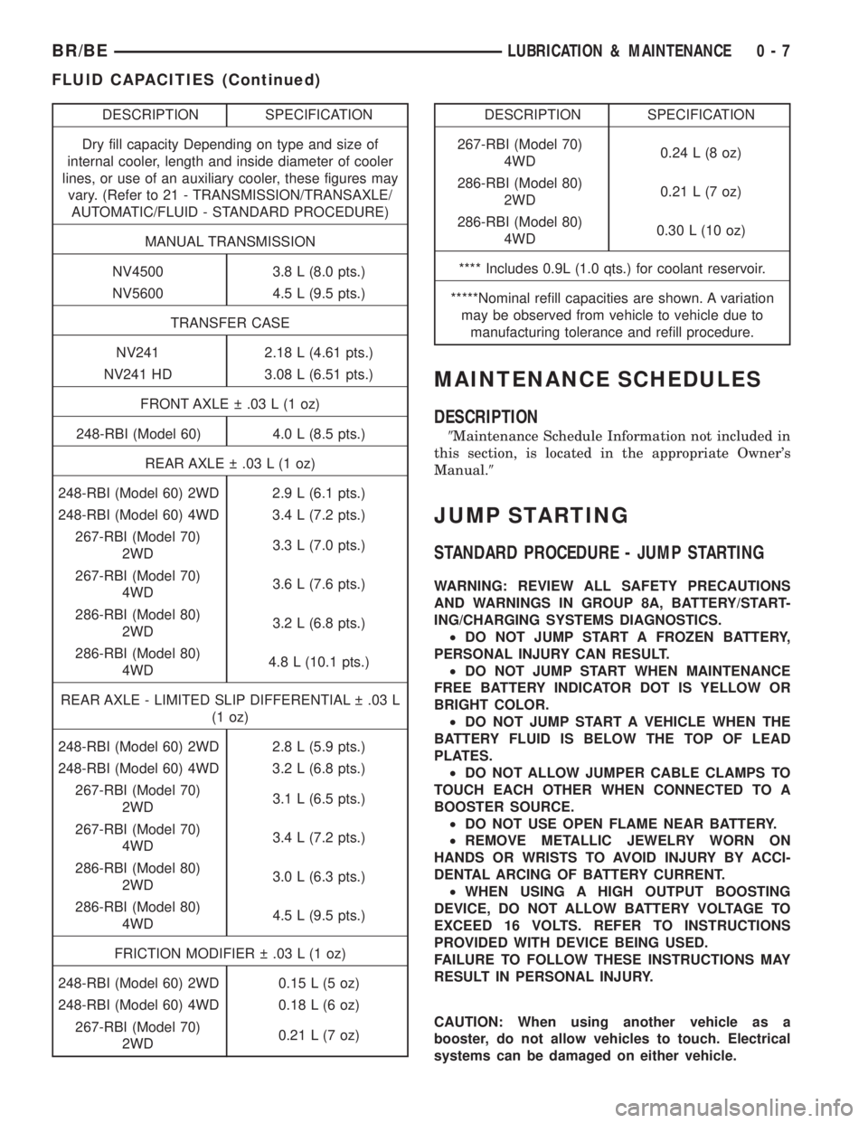
DESCRIPTION SPECIFICATION
Dry fill capacity Depending on type and size of
internal cooler, length and inside diameter of cooler
lines, or use of an auxiliary cooler, these figures may
vary. (Refer to 21 - TRANSMISSION/TRANSAXLE/
AUTOMATIC/FLUID - STANDARD PROCEDURE)
MANUAL TRANSMISSION
NV4500 3.8 L (8.0 pts.)
NV5600 4.5 L (9.5 pts.)
TRANSFER CASE
NV241 2.18 L (4.61 pts.)
NV241 HD 3.08 L (6.51 pts.)
FRONT AXLE .03 L (1 oz)
248-RBI (Model 60) 4.0 L (8.5 pts.)
REAR AXLE .03 L (1 oz)
248-RBI (Model 60) 2WD 2.9 L (6.1 pts.)
248-RBI (Model 60) 4WD 3.4 L (7.2 pts.)
267-RBI (Model 70)
2WD3.3 L (7.0 pts.)
267-RBI (Model 70)
4WD3.6 L (7.6 pts.)
286-RBI (Model 80)
2WD3.2 L (6.8 pts.)
286-RBI (Model 80)
4WD4.8 L (10.1 pts.)
REAR AXLE - LIMITED SLIP DIFFERENTIAL .03 L
(1 oz)
248-RBI (Model 60) 2WD 2.8 L (5.9 pts.)
248-RBI (Model 60) 4WD 3.2 L (6.8 pts.)
267-RBI (Model 70)
2WD3.1 L (6.5 pts.)
267-RBI (Model 70)
4WD3.4 L (7.2 pts.)
286-RBI (Model 80)
2WD3.0 L (6.3 pts.)
286-RBI (Model 80)
4WD4.5 L (9.5 pts.)
FRICTION MODIFIER .03 L (1 oz)
248-RBI (Model 60) 2WD 0.15 L (5 oz)
248-RBI (Model 60) 4WD 0.18 L (6 oz)
267-RBI (Model 70)
2WD0.21 L (7 oz)DESCRIPTION SPECIFICATION
267-RBI (Model 70)
4WD0.24 L (8 oz)
286-RBI (Model 80)
2WD0.21 L (7 oz)
286-RBI (Model 80)
4WD0.30 L (10 oz)
**** Includes 0.9L (1.0 qts.) for coolant reservoir.
*****Nominal refill capacities are shown. A variation
may be observed from vehicle to vehicle due to
manufacturing tolerance and refill procedure.
MAINTENANCE SCHEDULES
DESCRIPTION
9Maintenance Schedule Information not included in
this section, is located in the appropriate Owner's
Manual.9
JUMP STARTING
STANDARD PROCEDURE - JUMP STARTING
WARNING: REVIEW ALL SAFETY PRECAUTIONS
AND WARNINGS IN GROUP 8A, BATTERY/START-
ING/CHARGING SYSTEMS DIAGNOSTICS.
²DO NOT JUMP START A FROZEN BATTERY,
PERSONAL INJURY CAN RESULT.
²DO NOT JUMP START WHEN MAINTENANCE
FREE BATTERY INDICATOR DOT IS YELLOW OR
BRIGHT COLOR.
²DO NOT JUMP START A VEHICLE WHEN THE
BATTERY FLUID IS BELOW THE TOP OF LEAD
PLATES.
²DO NOT ALLOW JUMPER CABLE CLAMPS TO
TOUCH EACH OTHER WHEN CONNECTED TO A
BOOSTER SOURCE.
²DO NOT USE OPEN FLAME NEAR BATTERY.
²REMOVE METALLIC JEWELRY WORN ON
HANDS OR WRISTS TO AVOID INJURY BY ACCI-
DENTAL ARCING OF BATTERY CURRENT.
²WHEN USING A HIGH OUTPUT BOOSTING
DEVICE, DO NOT ALLOW BATTERY VOLTAGE TO
EXCEED 16 VOLTS. REFER TO INSTRUCTIONS
PROVIDED WITH DEVICE BEING USED.
FAILURE TO FOLLOW THESE INSTRUCTIONS MAY
RESULT IN PERSONAL INJURY.
CAUTION: When using another vehicle as a
booster, do not allow vehicles to touch. Electrical
systems can be damaged on either vehicle.
BR/BELUBRICATION & MAINTENANCE 0 - 7
FLUID CAPACITIES (Continued)
Page 250 of 2255
COOLING
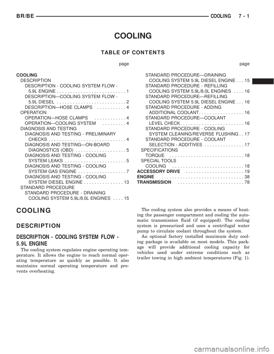
TABLE OF CONTENTS
page page
COOLING
DESCRIPTION
DESCRIPTION - COOLING SYSTEM FLOW -
5.9L ENGINE..........................1
DESCRIPTIONÐCOOLING SYSTEM FLOW -
5.9L DIESEL..........................2
DESCRIPTIONÐHOSE CLAMPS...........4
OPERATION
OPERATIONÐHOSE CLAMPS............4
OPERATIONÐCOOLING SYSTEM.........4
DIAGNOSIS AND TESTING
DIAGNOSIS AND TESTING - PRELIMINARY
CHECKS.............................4
DIAGNOSIS AND TESTINGÐON-BOARD
DIAGNOSTICS (OBD)...................5
DIAGNOSIS AND TESTING - COOLING
SYSTEM LEAKS.......................5
DIAGNOSIS AND TESTING - COOLING
SYSTEM GAS ENGINE..................7
DIAGNOSIS AND TESTING - COOLING
SYSTEM DIESEL ENGINE...............13
STANDARD PROCEDURE
STANDARD PROCEDURE - DRAINING
COOLING SYSTEM 5.9L/8.0L ENGINES....15STANDARD PROCEDUREÐDRAINING
COOLING SYSTEM 5.9L DIESEL ENGINE . . . 15
STANDARD PROCEDURE - REFILLING
COOLING SYSTEM 5.9L/8.0L ENGINES....16
STANDARD PROCEDUREÐREFILLING
COOLING SYSTEM 5.9L DIESEL ENGINE . . . 16
STANDARD PROCEDURE - ADDING
ADDITIONAL COOLANT.................16
STANDARD PROCEDUREÐCOOLANT
LEVEL CHECK........................16
STANDARD PROCEDURE - COOLING
SYSTEM CLEANING/REVERSE FLUSHING . . 17
STANDARD PROCEDURE - COOLANT
SELECTION - ADDITIVES...............17
SPECIFICATIONS
TORQUE............................18
SPECIAL TOOLS
COOLING...........................18
ACCESSORY DRIVE......................19
ENGINE...............................38
TRANSMISSION.........................78
COOLING
DESCRIPTION
DESCRIPTION - COOLING SYSTEM FLOW -
5.9L ENGINE
The cooling system regulates engine operating tem-
perature. It allows the engine to reach normal oper-
ating temperature as quickly as possible. It also
maintains normal operating temperature and pre-
vents overheating.The cooling system also provides a means of heat-
ing the passenger compartment and cooling the auto-
matic transmission fluid (if equipped). The cooling
system is pressurized and uses a centrifugal water
pump to circulate coolant throughout the system.
An optional factory installed maximum duty cool-
ing package is available on most models. This pack-
age will provide additional cooling capacity for
vehicles used under extreme conditions such as
trailer towing in high ambient temperatures (Fig. 1).
BR/BECOOLING 7 - 1
Page 253 of 2255
DESCRIPTIONÐHOSE CLAMPS
The cooling system utilizes both worm drive and
spring type hose clamps. If a spring type clamp
replacement is necessary, replace with the original
Mopartequipment spring type clamp.
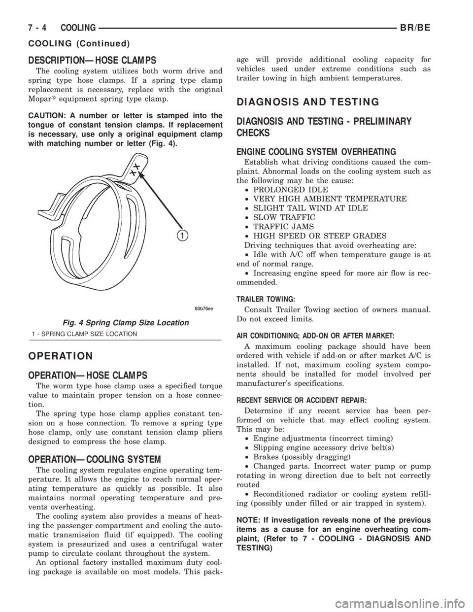
CAUTION: A number or letter is stamped into the
tongue of constant tension clamps. If replacement
is necessary, use only a original equipment clamp
with matching number or letter (Fig. 4).
OPERATION
OPERATIONÐHOSE CLAMPS
The worm type hose clamp uses a specified torque
value to maintain proper tension on a hose connec-
tion.
The spring type hose clamp applies constant ten-
sion on a hose connection. To remove a spring type
hose clamp, only use constant tension clamp pliers
designed to compress the hose clamp.
OPERATIONÐCOOLING SYSTEM
The cooling system regulates engine operating tem-
perature. It allows the engine to reach normal oper-
ating temperature as quickly as possible. It also
maintains normal operating temperature and pre-
vents overheating.
The cooling system also provides a means of heat-
ing the passenger compartment and cooling the auto-
matic transmission fluid (if equipped). The cooling
system is pressurized and uses a centrifugal water
pump to circulate coolant throughout the system.
An optional factory installed maximum duty cool-
ing package is available on most models. This pack-age will provide additional cooling capacity for
vehicles used under extreme conditions such as
trailer towing in high ambient temperatures.
DIAGNOSIS AND TESTING
DIAGNOSIS AND TESTING - PRELIMINARY
CHECKS
ENGINE COOLING SYSTEM OVERHEATING
Establish what driving conditions caused the com-
plaint. Abnormal loads on the cooling system such as
the following may be the cause:
²PROLONGED IDLE
²VERY HIGH AMBIENT TEMPERATURE
²SLIGHT TAIL WIND AT IDLE
²SLOW TRAFFIC
²TRAFFIC JAMS
²HIGH SPEED OR STEEP GRADES
Driving techniques that avoid overheating are:
²Idle with A/C off when temperature gauge is at
end of normal range.
²Increasing engine speed for more air flow is rec-
ommended.
TRAILER TOWING:
Consult Trailer Towing section of owners manual.
Do not exceed limits.
AIR CONDITIONING; ADD-ON OR AFTER MARKET:
A maximum cooling package should have been
ordered with vehicle if add-on or after market A/C is
installed. If not, maximum cooling system compo-
nents should be installed for model involved per
manufacturer's specifications.
RECENT SERVICE OR ACCIDENT REPAIR:
Determine if any recent service has been per-
formed on vehicle that may effect cooling system.
This may be:
²Engine adjustments (incorrect timing)
²Slipping engine accessory drive belt(s)
²Brakes (possibly dragging)
²Changed parts. Incorrect water pump or pump
rotating in wrong direction due to belt not correctly
routed
²Reconditioned radiator or cooling system refill-
ing (possibly under filled or air trapped in system).
NOTE: If investigation reveals none of the previous
items as a cause for an engine overheating com-
plaint, (Refer to 7 - COOLING - DIAGNOSIS AND
TESTING)
Fig. 4 Spring Clamp Size Location
1 - SPRING CLAMP SIZE LOCATION
7 - 4 COOLINGBR/BE
COOLING (Continued)
Page 302 of 2255
(4) Install thermostat into recessed machined
groove on intake manifold (Fig. 25).
(5) Install thermostat housing (Fig. 25).
(6) Install housing-to-intake manifold bolts.
Tighten bolts to 25 N´m (220 in. lbs.) torque.
CAUTION: Housing bolts should be tightened
evenly to prevent damage to housing and to pre-
vent leaks.
(7) Connect the wiring to both sensors.
(8) Install the upper radiator hose and hose clamp
to thermostat housing.
(9) Install support rod.
(10) Fill cooling system (Refer to 7 - COOLING -
STANDARD PROCEDURE).
(11) Connect negative battery cable to battery.
(12) Start and warm engine. Check for leaks.
ENGINE COOLANT
THERMOSTAT - 5.9L DIESEL
DESCRIPTION
CAUTION: Do not operate an engine without a ther-
mostat, except for servicing or testing. An engine
with the thermostat removed will operate in the
radiator bypass mode, causing an overheat condi-
tion.
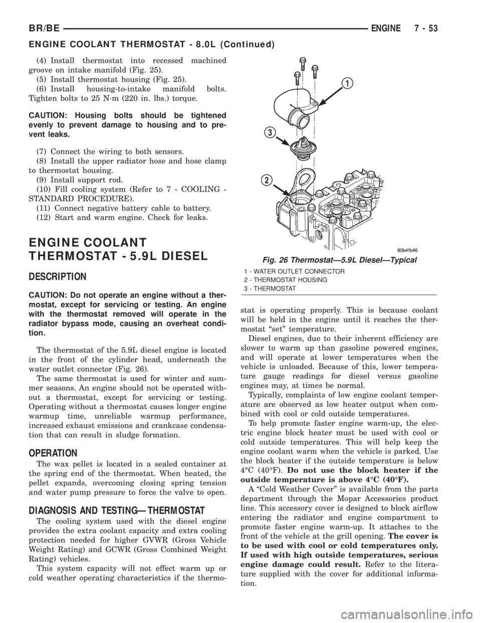
The thermostat of the 5.9L diesel engine is located
in the front of the cylinder head, underneath the
water outlet connector (Fig. 26).
The same thermostat is used for winter and sum-
mer seasons. An engine should not be operated with-
out a thermostat, except for servicing or testing.
Operating without a thermostat causes longer engine
warmup time, unreliable warmup performance,
increased exhaust emissions and crankcase condensa-
tion that can result in sludge formation.
OPERATION
The wax pellet is located in a sealed container at
the spring end of the thermostat. When heated, the
pellet expands, overcoming closing spring tension
and water pump pressure to force the valve to open.
DIAGNOSIS AND TESTINGÐTHERMOSTAT
The cooling system used with the diesel engine
provides the extra coolant capacity and extra cooling
protection needed for higher GVWR (Gross Vehicle
Weight Rating) and GCWR (Gross Combined Weight
Rating) vehicles.
This system capacity will not effect warm up or
cold weather operating characteristics if the thermo-stat is operating properly. This is because coolant
will be held in the engine until it reaches the ther-
mostat ªsetº temperature.
Diesel engines, due to their inherent efficiency are
slower to warm up than gasoline powered engines,
and will operate at lower temperatures when the
vehicle is unloaded. Because of this, lower tempera-
ture gauge readings for diesel versus gasoline
engines may, at times be normal.
Typically, complaints of low engine coolant temper-
ature are observed as low heater output when com-
bined with cool or cold outside temperatures.
To help promote faster engine warm-up, the elec-
tric engine block heater must be used with cool or
cold outside temperatures. This will help keep the
engine coolant warm when the vehicle is parked. Use
the block heater if the outside temperature is below
4ÉC (40ÉF).Do not use the block heater if the
outside temperature is above 4ÉC (40ÉF).
A ªCold Weather Coverº is available from the parts
department through the Mopar Accessories product
line. This accessory cover is designed to block airflow
entering the radiator and engine compartment to
promote faster engine warm-up. It attaches to the
front of the vehicle at the grill opening.The cover is
to be used with cool or cold temperatures only.
If used with high outside temperatures, serious
engine damage could result.Refer to the litera-
ture supplied with the cover for additional informa-
tion.
Fig. 26 ThermostatÐ5.9L DieselÐTypical
1 - WATER OUTLET CONNECTOR
2 - THERMOSTAT HOUSING
3 - THERMOSTAT
BR/BEENGINE 7 - 53
ENGINE COOLANT THERMOSTAT - 8.0L (Continued)
Page 313 of 2255
CLEANING
Clean radiator fins are necessary for good heat
transfer. The radiator and air conditioning fins
should be cleaned when an accumulation of debris
has occurred. With the engine cold, apply cold water
and compressed air to the back (engine side) of the
radiator to flush the radiator and/or A/C condenser of
debris.
INSPECTION
Inspect the radiator side tanks for cracks, broken
or missing fittings also inspect the joint where the
tanks seam up to the radiator core for signs of leak-
age and/or deteriorating seals.
Inspect radiator core for corroded, bent or missing
cooling fins. Inspect the core for bent or damaged
cooling tubes.
INSTALLATION
(1) Position fan shroud over the fan blades rear-
ward towards engine.
(2) Install rubber insulators to alignment dowels
at lower part of radiator.
(3) Lower the radiator into position while guiding
the two alignment dowels into lower radiator sup-
port. Different alignment holes are provided in the
lower radiator support for each engine application.
(4) Install two upper radiator mounting bolts.
Tighten bolts to 11 N´m (95 in. lbs.) torque.
(5) Connect both radiator hoses and install hose
clamps.
(6) Connect transmission cooler lines to radiator
tank. Inspect quick connect fittings for debris and
install until an audible ªclickº is heard. Pull apart to
verify connection.
(7) Install windshield washer reservoir tank.
(8) Position fan shroud to flanges on sides of radi-
ator. Install fan shroud mounting bolts (Fig. 41).
Tighten bolts to 6 N´m (50 in. lbs.) torque.
(9) Install metal clips to top of fan shroud.
(10) Install coolant reserve/overflow tank hose to
radiator filler neck nipple.
(11) Install coolant reserve/overflow tank to fan
shroud (fits into T-slots on shroud).
(12) Install battery negative cables.
(13) Install positive battery cable to top of radia-
tor. Tighten radiator-to-battery cable mounting nuts.
(14) Position heater controls tofull heatposition.
(15) Fill cooling system with coolant (Refer to 7 -
COOLING - STANDARD PROCEDURE).
(16) Operate engine until it reaches normal tem-
perature. Check cooling system and automatic trans-
mission (if equipped) fluid levels.
RADIATOR PRESSURE CAP
DESCRIPTION
Radiators are equipped with a pressure cap, which
releases pressure at some point within a range of
97-124 kPa (14-18 psi). The pressure relief point (in
pounds) is engraved on top of cap.
The cooling system will operate at pressures
slightly above atmospheric pressure. This results in a
higher coolant boiling point allowing increased radi-
ator cooling capacity.
A rubber gasket seals radiator filler neck to pre-
vent leakage. This is done to keep system under
pressure. It also maintains vacuum during coolant
cool-down allowing coolant to return from reserve/
overflow tank.
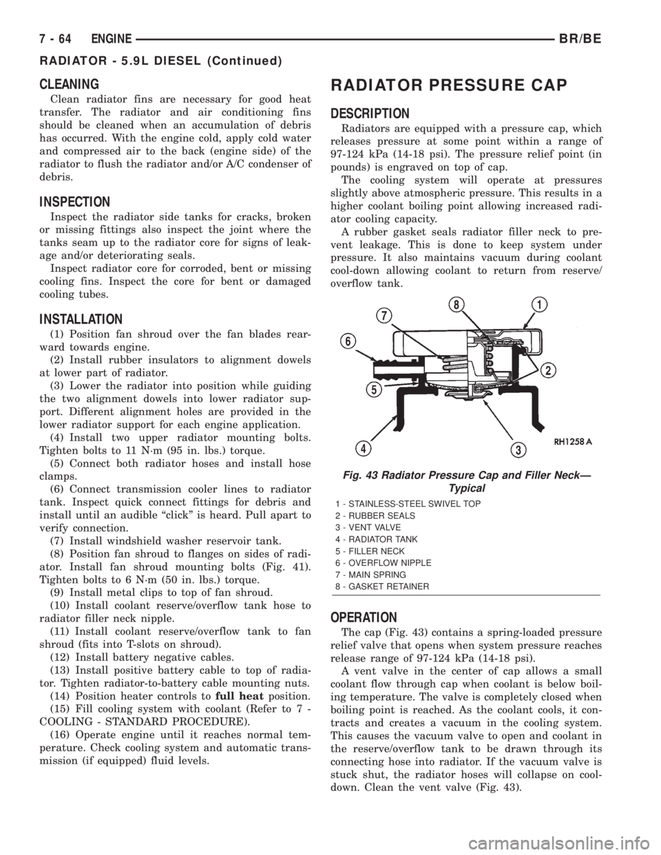
OPERATION
The cap (Fig. 43) contains a spring-loaded pressure
relief valve that opens when system pressure reaches
release range of 97-124 kPa (14-18 psi).
A vent valve in the center of cap allows a small
coolant flow through cap when coolant is below boil-
ing temperature. The valve is completely closed when
boiling point is reached. As the coolant cools, it con-
tracts and creates a vacuum in the cooling system.
This causes the vacuum valve to open and coolant in
the reserve/overflow tank to be drawn through its
connecting hose into radiator. If the vacuum valve is
stuck shut, the radiator hoses will collapse on cool-
down. Clean the vent valve (Fig. 43).
Fig. 43 Radiator Pressure Cap and Filler NeckÐ
Typical
1 - STAINLESS-STEEL SWIVEL TOP
2 - RUBBER SEALS
3 - VENT VALVE
4 - RADIATOR TANK
5 - FILLER NECK
6 - OVERFLOW NIPPLE
7 - MAIN SPRING
8 - GASKET RETAINER
7 - 64 ENGINEBR/BE
RADIATOR - 5.9L DIESEL (Continued)
Page 2198 of 2255
The catalyst monitor uses dual oxygen sensors
(O2S's) to monitor the efficiency of the converter. The
dual O2S's sensor strategy is based on the fact that
as a catalyst deteriorates, its oxygen storage capacity
and its efficiency are both reduced. By monitoring
the oxygen storage capacity of a catalyst, its effi-
ciency can be indirectly calculated. The upstream
O2S is used to detect the amount of oxygen in the
exhaust gas before the gas enters the catalytic con-
verter. The PCM calculates the A/F mixture from the
output of the O2S. A low voltage indicates high oxy-
gen content (lean mixture). A high voltage indicates a
low content of oxygen (rich mixture).
When the upstream O2S detects a lean condition,
there is an abundance of oxygen in the exhaust gas.
A functioning converter would store this oxygen so it
can use it for the oxidation of HC and CO. As the
converter absorbs the oxygen, there will be a lack of
oxygen downstream of the converter. The output of
the downstream O2S will indicate limited activity in
this condition.
As the converter loses the ability to store oxygen,
the condition can be detected from the behavior of
the downstream O2S. When the efficiency drops, no
chemical reaction takes place. This means the con-
centration of oxygen will be the same downstream as
upstream. The output voltage of the downstream
O2S copies the voltage of the upstream sensor. The
only difference is a time lag (seen by the PCM)
between the switching of the O2S's.
To monitor the system, the number of lean-to-rich
switches of upstream and downstream O2S's is
counted. The ratio of downstream switches to
upstream switches is used to determine whether the
catalyst is operating properly. An effective catalyst
will have fewer downstream switches than it has
upstream switches i.e., a ratio closer to zero. For a
totally ineffective catalyst, this ratio will be one-to-
one, indicating that no oxidation occurs in the device.
The system must be monitored so that when cata-
lyst efficiency deteriorates and exhaust emissions
increase to over the legal limit, the MIL will be illu-
minated.
DESCRIPTION - TRIP DEFINITION
The term ªTripº has different meanings depending
on what the circumstances are. If the MIL (Malfunc-
tion Indicator Lamp) is OFF, a Trip is defined as
when the Oxygen Sensor Monitor and the Catalyst
Monitor have been completed in the same drive cycle.
When any Emission DTC is set, the MIL on the
dash is turned ON. When the MIL is ON, it takes 3
good trips to turn the MIL OFF. In this case, it
depends on what type of DTC is set to know what a
ªTripº is.For the Fuel Monitor or Mis-Fire Monitor (contin-
uous monitor), the vehicle must be operated in the
ªSimilar Condition Windowº for a specified amount of
time to be considered a Good Trip.
If a Non-Contiuous OBDII Monitor fails twice in a
row and turns ON the MIL, re-running that monitor
which previously failed, on the next start-up and
passing the monitor, is considered to be a Good Trip.
These will include the following:
²Oxygen Sensor
²Catalyst Monitor
²Purge Flow Monitor
²Leak Detection Pump Monitor (if equipped)
²EGR Monitor (if equipped)
²Oxygen Sensor Heater Monitor
If any other Emission DTC is set (not an OBDII
Monitor), a Good Trip is considered to be when the
Oxygen Sensor Monitor and Catalyst Monitor have
been completed; or 2 Minutes of engine run time if
the Oxygen Sensor Monitor or Catalyst Monitor have
been stopped from running.
It can take up to 2 Failures in a row to turn on the
MIL. After the MIL is ON, it takes 3 Good Trips to
turn the MIL OFF. After the MIL is OFF, the PCM
will self-erase the DTC after 40 Warm-up cycles. A
Warm-up cycle is counted when the ECT (Engine
Coolant Temperature Sensor) has crossed 160ÉF and
has risen by at least 40ÉF since the engine has been
started.
DESCRIPTION - COMPONENT MONITORS -
GAS ENGINES
There are several components that will affect vehi-
cle emissions if they malfunction. If one of these com-
ponents malfunctions the Malfunction Indicator
Lamp (MIL) will illuminate.
Some of the component monitors are checking for
proper operation of the part. Electrically operated
components now have input (rationality) and output
(functionality) checks. Previously, a component like
the Throttle Position sensor (TPS) was checked by
the PCM for an open or shorted circuit. If one of
these conditions occurred, a DTC was set. Now there
is a check to ensure that the component is working.
This is done by watching for a TPS indication of a
greater or lesser throttle opening than MAP and
engine rpm indicate. In the case of the TPS, if engine
vacuum is high and engine rpm is 1600 or greater,
and the TPS indicates a large throttle opening, a
DTC will be set. The same applies to low vacuum if
the TPS indicates a small throttle opening.
All open/short circuit checks, or any component
that has an associated limp-in, will set a fault after 1
trip with the malfunction present. Components with-
out an associated limp-in will take two trips to illu-
minate the MIL.
BR/BEEMISSIONS CONTROL 25 - 19
EMISSIONS CONTROL (Continued)
Page 2241 of 2255
PRESSURE SWITCH - OPERATION, A/C
HIGH..............................24-20
PRESSURE SWITCH - OPERATION, A/C
LOW ..............................24-21
PRESSURE SWITCH - REMOVAL, A/C
HIGH..............................24-20
PRESSURE SWITCH - REMOVAL, A/C
LOW ..............................24-21
PRESSURE TEST - DIAGNOSIS AND
TESTING, FUEL PUMP..................14-9
PRESSURE TEST - DIAGNOSIS AND
TESTING, HYDRAULIC...........21-270,21-98
PRESSURES - DESCRIPTION, TIRE
INFLATION...........................22-7
PRESSURES, DIESEL ENGINES - FUEL
SYSTEM............................14-62
PROGRAMMING - STANDARD
PROCEDURE, RKE TRANSMITTER........8N-8
PROPELLER SHAFT - DIAGNOSIS AND
TESTING.............................3-1
PROPELLER SHAFT - FRONT -
INSTALLATION.........................3-7
PROPELLER SHAFT - FRONT - REMOVAL . . . 3-6
PROPELLER SHAFT - REAR -
INSTALLATION.........................3-7
PROPELLER SHAFT - REAR - REMOVAL....3-7
PROPELLER SHAFT - STANDARD
PROCEDURES.........................3-3
PROPELLER SHAFT, SPECIAL TOOLS.......3-6
PROPELLER SHAFT, SPECIFICATIONS.......3-6
PTO SWITCH - DESCRIPTION...........14-47
PTO SWITCH - OPERATION..............14-47
PULLEY - INSTALLATION..............19-39
PULLEY - REMOVAL..................19-38
PUMP - 5.9L - CLEANING, WATER........7-68
PUMP - 5.9L - DESCRIPTION, WATER.....7-66
PUMP - 5.9L - INSPECTION, WATER......7-68
PUMP - 5.9L - INSTALLATION, WATER.....7-68
PUMP - 5.9L - OPERATION, WATER.......7-66
PUMP - 5.9L - REMOVAL, WATER........7-66
PUMP - 5.9L DIESEL - CLEANING,
WATER .............................7-72
PUMP - 5.9L DIESEL - DESCRIPTION,
VACUUM............................7-33
PUMP - 5.9L DIESEL - DESCRIPTION,
WATER .............................7-72
PUMP - 5.9L DIESEL - INSPECTION,
WATER .............................7-72
PUMP - 5.9L DIESEL - INSTALLATION,
VACUUM............................7-36
PUMP - 5.9L DIESEL - INSTALLATION,
WATER .............................7-72
PUMP - 5.9L DIESEL - OPERATION,
VACUUM............................7-34
PUMP - 5.9L DIESEL - OPERATION,
WATER .............................7-72
PUMP - 5.9L DIESEL - REMOVAL,
VACUUM............................7-34
PUMP - 5.9L DIESEL - REMOVAL,
WATER .............................7-72
PUMP - 8.0L - CLEANING, WATER........7-71
PUMP - 8.0L - INSPECTION, WATER......7-71
PUMP - 8.0L - INSTALLATION, WATER.....7-71
PUMP - 8.0L - REMOVAL, WATER........7-69
PUMP - ASSEMBLY, OIL................9-49
PUMP - ASSEMBLY, OIL........21-169,21-340
PUMP - CLEANING, OIL..........9-104,9-181
PUMP - CLEANING, OIL........21-168,21-338
PUMP - DESCRIPTION................19-33
PUMP - DESCRIPTION, AIR INJECTION . . . 25-29
PUMP - DESCRIPTION, FUEL
............14-9
PUMP - DESCRIPTION, FUEL TRANSFER
. . 14-83
PUMP - DESCRIPTION, LEAK DETECTION
. 25-34
PUMP - DESCRIPTION, OIL
......21-166,21-336
PUMP - DIAGNOSIS AND TESTING, AIR
INJECTION
..........................25-29
PUMP - DIAGNOSIS AND TESTING,
WATER
.....................7-66,7-69,7-72
PUMP - DISASSEMBLY, OIL
.............9-47
PUMP - DISASSEMBLY, OIL
.....21-167,21-337
PUMP - INITIAL OPERATION -
STANDARD PROCEDURE, POWER
STEERING
..........................19-33
PUMP - INSPECTION, OIL
.....9-104,9-181,9-47
PUMP - INSPECTION, OIL
.......21-168,21-339
PUMP - INSTALLATION, AIR INJECTION
. . . 25-30
PUMP - INSTALLATION, FUEL TRANSFER
. 14-87PUMP - INSTALLATION, LEAK
DETECTION.........................25-34
PUMP - INSTALLATION, OIL . . . 9-106,9-182,9-50
PUMP - OPERATION..................19-33
PUMP - OPERATION, AIR INJECTION.....25-29
PUMP - OPERATION, FUEL..............14-9
PUMP - OPERATION, FUEL TRANSFER....14-83
PUMP - OPERATION, LEAK DETECTION . . . 25-34
PUMP - OPERATION, OIL.......21-166,21-336
PUMP - REMOVAL, AIR INJECTION......25-30
PUMP - REMOVAL, FUEL TRANSFER.....14-86
PUMP - REMOVAL, LEAK DETECTION....25-34
PUMP - REMOVAL, OIL.......9-104,9-181,9-47
PUMP 235 H.P. - DESCRIPTION, FUEL....14-69
PUMP 245 H.P. - DESCRIPTION, FUEL....14-69
PUMP AMPERAGE TEST - DIAGNOSIS
AND TESTING, FUEL..................14-10
PUMP BYPASS HOSE WITH AIR
CONDITIONING - INSTALLATION,
WATER .............................7-76
PUMP BYPASS HOSE WITH AIR
CONDITIONING - REMOVAL, WATER......7-73
PUMP BYPASS HOSE WITHOUT AIR
CONDITIONING - INSTALLATION,
WATER .............................7-77
PUMP BYPASS HOSE WITHOUT AIR
CONDITIONING - REMOVAL, WATER......7-76
PUMP CAPACITY TEST - DIAGNOSIS
AND TESTING, FUEL...................14-9
PUMP DATA PLATE, SPECIFICATIONS -
FUEL INJECTION.....................14-77
PUMP FILTER - INSTALLATION, AIR......25-30
PUMP FILTER - REMOVAL, AIR.........25-30
PUMP LEAKAGE - DIAGNOSIS AND
TESTING...........................19-33
PUMP MODULE - DESCRIPTION, FUEL....14-12
PUMP MODULE - INSTALLATION, FUEL . . . 14-13
PUMP MODULE - OPERATION, FUEL.....14-13
PUMP MODULE - REMOVAL, FUEL.......14-13
PUMP OUTPUT - DIAGNOSIS AND
TESTING, VACUUM....................7-34
PUMP PRESSURE - DIAGNOSIS AND
TESTING, FUEL TRANSFER.............14-84
PUMP PRESSURE TEST - DIAGNOSIS
AND TESTING, FUEL...................14-9
PUMP RELAY - DESCRIPTION, FUEL.....14-40
PUMP RELAY - DESCRIPTION, FUEL
INJECTION.........................14-103
PUMP RELAY - INSTALLATION, FUEL.....14-40
PUMP RELAY - OPERATION, FUEL.......14-40
PUMP RELAY - OPERATION, FUEL
INJECTION.........................14-103
PUMP RELAY - REMOVAL, FUEL........14-40
PUMP RELAYS - DIAGNOSIS AND
TESTING, ASD AND FUEL...............8I-4
PUMP, SPECIAL TOOLS - POWER
STEERING..........................19-38
PUMP TIMING - DIAGNOSIS AND
TESTING, FUEL INJECTION.............14-70
PUMP VOLUME CHECK - STANDARD
PROCEDURE, OIL.............21-166,21-336
PUMP/MOTOR - DESCRIPTION, WASHER . . 8R-9
PUMP/MOTOR - INSTALLATION,
WASHER...........................8R-10
PUMP/MOTOR - OPERATION, WASHER....8R-9
PUMP/MOTOR - REMOVAL, WASHER....8R-10
PUSHRODS - CLEANING...............9-134
PUSHRODS - INSPECTION.............9-135
QUARTER TRIM PANEL - INSTALLATION . 23-128
QUARTER TRIM PANEL - REMOVAL.....23-128
QUARTER WINDOW - INSTALLATION....23-150
QUARTER WINDOW - REMOVAL
........23-150
QUICK CONNECT FITTING -
DESCRIPTION
.......................14-24
QUICK-CONNECT FITTINGS - STANDARD
PROCEDURE
........................14-24
RADIAL-PLY TIRES - DESCRIPTION
.......22-6
RADIATOR - 5.9L - CLEANING
...........7-59
RADIATOR - 5.9L - DESCRIPTION
........7-58
RADIATOR - 5.9L - INSPECTION
..........7-60
RADIATOR - 5.9L - INSTALLATION
........7-60
RADIATOR - 5.9L - OPERATION
..........7-58
RADIATOR - 5.9L - REMOVAL
............7-58
RADIATOR - 5.9L DIESEL - CLEANING
.....7-64
RADIATOR - 5.9L DIESEL -
DESCRIPTION
........................7-62
RADIATOR - 5.9L DIESEL - INSPECTION
. . . 7-64RADIATOR - 5.9L DIESEL -
INSTALLATION........................7-64
RADIATOR - 5.9L DIESEL - OPERATION....7-62
RADIATOR - 5.9L DIESEL - REMOVAL.....7-62
RADIATOR - 8.0L - CLEANING...........7-61
RADIATOR - 8.0L - DESCRIPTION........7-60
RADIATOR - 8.0L - INSPECTION..........7-61
RADIATOR - 8.0L - INSTALLATION........7-61
RADIATOR - 8.0L - OPERATION..........7-60
RADIATOR - 8.0L - REMOVAL............7-60
RADIATOR CAP - DIAGNOSIS AND
TESTING............................7-65
RADIATOR CAP-TO-FILLER NECK SEAL -
DIAGNOSIS AND TESTING..............7-65
RADIATOR COOLANT FLOW -
DIAGNOSIS AND TESTING......7-58,7-60,7-62
RADIATOR FAN - 5.9L DIESEL -
CLEANING...........................7-43
RADIATOR FAN - 5.9L DIESEL -
INSPECTION.........................7-43
RADIATOR FAN - 5.9L DIESEL -
INSTALLATION........................7-44
RADIATOR FAN - 5.9L DIESEL -
REMOVAL...........................7-43
RADIATOR FAN - 5.9L/8.0L - CLEANING....7-42
RADIATOR FAN - 5.9L/8.0L -
INSPECTION.........................7-42
RADIATOR FAN - 5.9L/8.0L -
INSTALLATION........................7-42
RADIATOR FAN - 5.9L/8.0L - REMOVAL....7-41
RADIATOR PRESSURE CAP -
DESCRIPTION........................7-64
RADIATOR PRESSURE CAP - OPERATION . . 7-64
RADIO - DESCRIPTION................8A-10
RADIO - DIAGNOSIS AND TESTING......8A-10
RADIO - INSTALLATION...............8A-11
RADIO - OPERATION..................8A-10
RADIO - REMOVAL...................8A-11
RADIO CHOKE RELAY - DESCRIPTION.....8A-7
RADIO CHOKE RELAY - DIAGNOSIS AND
TESTING............................8A-8
RADIO CHOKE RELAY - INSTALLATION....8A-9
RADIO CHOKE RELAY - OPERATION.......8A-8
RADIO CHOKE RELAY - REMOVAL........8A-8
RADIO NOISE SUPPRESSION
COMPONENTS - DESCRIPTION..........8A-12
RADIO NOISE SUPPRESSION
COMPONENTS - DIAGNOSIS AND
TESTING...........................8A-12
RATINGS, SPECIFICATIONS -
GENERATOR........................8F-26
RBI - REAR AXLE, 286................3-120
RE TRANSMISSION, SPECIAL TOOLS . . . 21-146,
21-316
READING LAMP - DESCRIPTION.........8L-36
READING LAMP - INSTALLATION........8L-37
READING LAMP - OPERATION..........8L-36
READING LAMP - REMOVAL............8L-36
REAR - DESCRIPTION..................2-25
REAR - DESCRIPTION, CRANKSHAFT OIL
SEAL...............................9-33
REAR - INSTALLATION.........5-14,5-22,5-25
REAR - INSTALLATION................22-12
REAR - INSTALLATION, CRANKSHAFT
OIL SEAL...................9-162,9-34,9-90
REAR - INSTALLATION, PROPELLER
SHAFT...............................3-7
REAR - OPERATION, CRANKSHAFT OIL
SEAL...............................9-33
REAR - REMOVAL.............5-10,5-21,5-23
REAR - REMOVAL, CRANKSHAFT OIL
SEAL......................9-161,9-33,9-90
REAR - REMOVAL, PROPELLER SHAFT.....3-7
REAR AXLE - 248RBI - ADJUSTMENTS....3-51
REAR AXLE - 248RBI - DESCRIPTION.....3-46
REAR AXLE - 248RBI - INSTALLATION.....3-51
REAR AXLE - 248RBI - OPERATION.......3-46
REAR AXLE - 248RBI - REMOVAL........3-51
REAR AXLE - 267RBI - ADJUSTMENTS....3-83
REAR AXLE - 267RBI - DESCRIPTION.....3-78
REAR AXLE - 267RBI - INSTALLATION.....3-82
REAR AXLE - 267RBI - OPERATION.......3-78
REAR AXLE - 267RBI - REMOVAL........3-82
REAR AXLE - 286RBI - ADJUSTMENTS
. . . 3-112
REAR AXLE - 286RBI - DESCRIPTION
....3-107
REAR AXLE - 286RBI - INSTALLATION
....3-112
REAR AXLE - 286RBI - OPERATION
......3-108
REAR AXLE - 286RBI - REMOVAL
.......3-112
24 INDEXBR/BE
Description Group-Page Description Group-Page Description Group-Page
Page 2248 of 2255
SYSTEM - DIAGNOSIS AND TESTING,
POWER LOCK & REMOTE KEYLESS
ENTRY..............................8N-5
SYSTEM - DIAGNOSIS AND TESTING,
POWER SEAT.......................8N-16
SYSTEM - DIAGNOSIS AND TESTING,
POWER STEERING....................19-2
SYSTEM - DIAGNOSIS AND TESTING,
STARTING..........................8F-32
SYSTEM - DIAGNOSIS AND TESTING,
TURN SIGNAL & HAZARD WARNING......8L-3
SYSTEM - DIAGNOSIS AND TESTING,
VACUUM...........................24-10
SYSTEM - DIAGNOSIS AND TESTING,
VEHICLE THEFT SECURITY..............8Q-3
SYSTEM - DIAGNOSIS AND TESTING,
WIPER & WASHER....................8R-3
SYSTEM - INSPECTION, BATTERY........8F-6
SYSTEM - INSPECTION, WIPER &
WASHER............................8R-6
SYSTEM - LEAKS - DIAGNOSIS AND
TESTING, CHARGE AIR COOLER.........11-18
SYSTEM - OPERATION, AIR INJECTION . . . 25-28
SYSTEM - OPERATION, BATTERY.........8F-2
SYSTEM - OPERATION, CHIME
WARNING...........................8B-1
SYSTEM - OPERATION, COOLING..........7-4
SYSTEM - OPERATION, FUEL DELIVERY . . . 14-2
SYSTEM - OPERATION, HEATED MIRROR . . 8G-2
SYSTEM - OPERATION, HEATED SEAT.....8G-6
SYSTEM - OPERATION, INSTRUMENT
PANEL..............................23-106
SYSTEM - OPERATION, POWER SEAT....8N-16
SYSTEM - OPERATION, REMOTE
KEYLESS ENTRY......................8N-4
SYSTEM - OPERATION, SPEED CONTROL . . 8P-2
SYSTEM - OPERATION, TURN SIGNAL &
HAZARD WARNING....................8L-2
SYSTEM - SPECIAL TOOLS, AIRBAG......8O-6
SYSTEM - SPECIFICATIONS, TORQUE -
GENERATOR/CHARGING...............8F-27
SYSTEM - SPECIFICATIONS, TORQUE -
STARTING..........................8F-37
SYSTEM - STANDARD PROCEDURE,
BLEEDING ABS BRAKE.................5-36
SYSTEM - STANDARD PROCEDURE,
FLUSHING POWER STEERING...........19-34
SYSTEM - TORQUE, AIR INJECTION......25-29
SYSTEM - TORQUE, EVAP..............25-32
SYSTEM - TORQUE, SPEED CONTROL.....8P-4
SYSTEM 5.9L DIESEL ENGINE -
STANDARD PROCEDURE, DRAINING
COOLING............................7-15
SYSTEM 5.9L DIESEL ENGINE -
STANDARD PROCEDURE, REFILLING
COOLING............................7-16
SYSTEM 5.9L/8.0L ENGINES -
STANDARD PROCEDURE, DRAINING
COOLING............................7-15
SYSTEM 5.9L/8.0L ENGINES -
STANDARD PROCEDURE, REFILLING
COOLING............................7-16
SYSTEM AIR LEAK VACUUM TEST -
DIAGNOSIS AND TESTING, FUEL........14-57
SYSTEM AIRFLOW - DESCRIPTION,
HVAC..............................24-30
SYSTEM CHARGE - STANDARD
PROCEDURE, REFRIGERANT............24-46
SYSTEM CLEANING/REVERSE FLUSHING
- STANDARD PROCEDURE, COOLING......7-17
SYSTEM DIESEL ENGINE - DIAGNOSIS
AND TESTING, COOLING................7-13
SYSTEM EVACUATE - STANDARD
PROCEDURE, REFRIGERANT............24-46
SYSTEM FLOW - 5.9L DIESEL -
DESCRIPTION, COOLING.................7-2
SYSTEM FLOW - 5.9L ENGINE -
DESCRIPTION, COOLING.................7-1
SYSTEM GAS ENGINE - DIAGNOSIS AND
TESTING, COOLING
.....................7-7
SYSTEM LEAKS - DIAGNOSIS AND
TESTING, COOLING
.....................7-5
SYSTEM LEAKS - DIAGNOSIS AND
TESTING, REFRIGERANT
...............24-43
SYSTEM PARTS - STANDARD
PROCEDURES, CLEANING FUEL
.........14-61
SYSTEM PRESSURE - GAS ENGINES -
SPECIFICATIONS, FUEL
.................14-3SYSTEM PRESSURE RELEASE -
STANDARD PROCEDURE, FUEL..........14-3
SYSTEM PRESSURES, DIESEL ENGINES
- FUEL.............................14-62
SYSTEM REQUIREMENTS -
DESCRIPTION, COOLING................24-1
SYSTEM SERVICE EQUIPMENT -
STANDARD PROCEDURE,
REFRIGERANT.......................24-45
SYSTEM SERVICE PORT - DESCRIPTION,
REFRIGERANT........................24-1
SYSTEM SERVICE PORT - OPERATION,
REFRIGERANT........................24-2
SYSTEM, SPECIAL TOOLS - DIESEL
FUEL..............................14-63
SYSTEM, SPECIAL TOOLS - FUEL . . . 14-35,14-4
SYSTEM, SPECIFICATIONS - STARTING . . . 8F-36
SYSTEMS - DESCRIPTION, MONITORED . . 25-17
SYSTEMS, SPECIAL TOOLS - AUDIO......8A-4
SYSTEMS, SPECIAL TOOLS - POWER
DISTRIBUTION....................8W-97-2
TABLE, SPECIFICATIONS - A/C
APPLICATION........................24-7
TACHOMETER - DESCRIPTION..........8J-30
TACHOMETER - OPERATION............8J-30
TAIL LAMP - DESCRIPTION............8L-29
TAIL LAMP - INSTALLATION............8L-30
TAIL LAMP - OPERATION..............8L-29
TAIL LAMP - REMOVAL................8L-29
TAIL LAMP UNIT - INSTALLATION.......8L-30
TAIL LAMP UNIT - REMOVAL...........8L-30
TAILGATE - INSTALLATION.............23-67
TAILGATE - REMOVAL.................23-67
TAILPIPE - 3.9L/5.2L/5.9L - INSPECTION . . 11-11
TAILPIPE - 3.9L/5.2L/5.9L -
INSTALLATION.......................11-11
TAILPIPE - 3.9L/5.2L/5.9L - REMOVAL....11-11
TAILPIPE - 5.9L DIESEL - INSPECTION....11-12
TAILPIPE - 5.9L DIESEL - INSTALLATION . . 11-13
TAILPIPE - 5.9L DIESEL - REMOVAL.....11-12
TAILPIPE - 5.9L HD/8.0L - INSPECTION . . . 11-12
TAILPIPE - 5.9L HD/8.0L -
INSTALLATION.......................11-12
TAILPIPE - 5.9L HD/8.0L - REMOVAL.....11-12
TANK - DESCRIPTION, DIESEL FUEL.....14-82
TANK - DESCRIPTION, FUEL............14-18
TANK - INSTALLATION, FUEL...........14-20
TANK - OPERATION, FUEL..............14-18
TANK - REMOVAL, FUEL...............14-18
TANK CHECK VALVE - DESCRIPTION,
FUEL..............................14-21
TANK CHECK VALVE - INSTALLATION,
FUEL..............................14-23
TANK CHECK VALVE - REMOVAL, FUEL . . . 14-22
TANK MODULE - DESCRIPTION, FUEL....14-82
TANK MODULE - INSTALLATION, FUEL....14-83
TANK MODULE - OPERATION, FUEL......14-82
TANK MODULE - REMOVAL, FUEL.......14-83
TAPE STRIPE - INSTALLATION..........23-89
TAPE STRIPE - REMOVAL..............23-88
TAPPETS - DIAGNOSIS AND TESTING,
HYDRAULIC......................9-36,9-91
TASK MANAGER - DESCRIPTION........25-17
TASK MANAGER - OPERATION..........25-21
TEMP SENSOR - 5.9L - DESCRIPTION,
ENGINE COOLANT.....................7-47
TEMP SENSOR - 5.9L - INSTALLATION,
ENGINE COOLANT.....................7-47
TEMP SENSOR - 5.9L - OPERATION,
ENGINE COOLANT.....................7-47
TEMP SENSOR - 5.9L - REMOVAL,
ENGINE COOLANT.....................7-47
TEMP SENSOR - DESCRIPTION,
AMBIENT..........................8M-12
TEMP SENSOR - INSTALLATION,
AMBIENT..........................8M-13
TEMP SENSOR - OPERATION, AMBIENT . . 8M-12
TEMP SENSOR - REMOVAL, AMBIENT . . . 8M-12
TEMPERATURE GAUGE - DESCRIPTION,
ENGINE
............................8J-18
TEMPERATURE GAUGE - OPERATION,
ENGINE
............................8J-19
TEMPERATURE SENSOR - DESCRIPTION,
BATTERY
...........................8F-27
TEMPERATURE SENSOR - DESCRIPTION,
FUEL
.............................14-104
TEMPERATURE SENSOR - DESCRIPTION,
TRANSMISSION
...............21-218,21-390TEMPERATURE SENSOR - DIAGNOSIS
AND TESTING, AMBIENT..............8M-12
TEMPERATURE SENSOR -
INSTALLATION, BATTERY..............8F-28
TEMPERATURE SENSOR - OPERATION,
BATTERY...........................8F-27
TEMPERATURE SENSOR - OPERATION,
FUEL.............................14-104
TEMPERATURE SENSOR - OPERATION,
TRANSMISSION...............21-218,21-390
TEMPERATURE SENSOR - REMOVAL,
BATTERY...........................8F-27
TEMPORARY - DESCRIPTION, SPARE
TIRE................................22-6
TENSIONERS - 5.9L - DESCRIPTION,
BELT ...............................7-19
TENSIONERS - 5.9L - INSTALLATION,
BELT ...............................7-20
TENSIONERS - 5.9L - OPERATION, BELT . . . 7-19
TENSIONERS - 5.9L - REMOVAL, BELT.....7-19
TENSIONERS - 5.9L DIESEL -
DESCRIPTION, BELT...................7-23
TENSIONERS - 5.9L DIESEL -
INSTALLATION, BELT...................7-23
TENSIONERS - 5.9L DIESEL -
OPERATION, BELT.....................7-23
TENSIONERS - 5.9L DIESEL - REMOVAL,
BELT ...............................7-23
TENSIONERS - 8.0L - DESCRIPTION,
BELT ...............................7-20
TENSIONERS - 8.0L - INSTALLATION,
BELT ...............................7-22
TENSIONERS - 8.0L - OPERATION, BELT.....7-21
TENSIONERS - 8.0L - REMOVAL, BELT.....7-21
TERMINAL - INSTALLATION.........8W-01-13
TERMINAL - REMOVAL.............8W-01-13
TEST - DIAGNOSIS AND TESTING, FUEL
INJECTOR..........................14-99
TEST - DIAGNOSIS AND TESTING, FUEL
PRESSURE LEAK DOWN................14-2
TEST - DIAGNOSIS AND TESTING, FUEL
PUMP AMPERAGE....................14-10
TEST - DIAGNOSIS AND TESTING, FUEL
PUMP CAPACITY......................14-9
TEST - DIAGNOSIS AND TESTING, FUEL
PUMP PRESSURE.....................14-9
TEST - DIAGNOSIS AND TESTING, FUEL
SYSTEM AIR LEAK VACUUM............14-57
TEST - DIAGNOSIS AND TESTING,
HYDRAULIC PRESSURE.........21-270,21-98
TEST - DIAGNOSIS AND TESTING, ROAD . . . 8P-4
TEST - DIAGNOSIS AND TESTING,
VACUUM SUPPLY.....................8P-3
TEST - STANDARD PROCEDURE,
BUILT-IN INDICATOR..................8F-10
TEST - STANDARD PROCEDURE,
HYDROMETER.......................8F-11
TEST - STANDARD PROCEDURE,
IGNITION-OFF DRAW..................8F-13
TEST - STANDARD PROCEDURE, LOAD . . . 8F-12
TEST - STANDARD PROCEDURE,
OPEN-CIRCUIT VOLTAGE...............8F-12
TEST - STANDARD PROCEDURE,
VERIFICATION........................8O-5
TEST MODE - DESCRIPTION, CIRCUIT
ACTUATION
..........................25-2
TEST MODE - DESCRIPTION, STATE
DISPLAY
............................25-1
TETHER - INSTALLATION, CHILD
.........8O-9
TETHER - REMOVAL, CHILD
.............8O-9
THEFT SECURITY - DESCRIPTION,
VEHICLE
............................8Q-1
THEFT SECURITY - OPERATION, VEHICLE
. . 8Q-2
THEFT SECURITY SYSTEM - DIAGNOSIS
AND TESTING, VEHICLE
................8Q-3
THERMOSTAT - 5.9L - DESCRIPTION,
ENGINE COOLANT
.....................7-48
THERMOSTAT - 5.9L - INSTALLATION,
ENGINE COOLANT
.....................7-49
THERMOSTAT - 5.9L - OPERATION,
ENGINE COOLANT
.....................7-48
THERMOSTAT - 5.9L - REMOVAL,
ENGINE COOLANT
.....................7-48
THERMOSTAT - 5.9L DIESEL -
DESCRIPTION, ENGINE COOLANT
.........7-53
THERMOSTAT - 5.9L DIESEL -
INSTALLATION, ENGINE COOLANT
........7-54
BR/BEINDEX 31
Description Group-Page Description Group-Page Description Group-Page