Rear band DODGE RAM 2002 Service Repair Manual
[x] Cancel search | Manufacturer: DODGE, Model Year: 2002, Model line: RAM, Model: DODGE RAM 2002Pages: 2255, PDF Size: 62.07 MB
Page 225 of 2255
OPERATION
Battery voltage is supplied to the CAB when a
speed of 15 miles per hour is reached. The CAB per-
forms a system initialization procedure at this point.
Initialization consists of a static and dynamic self
check of system electrical components.
The static and dynamic checks occurs at ignition
start up. During the dynamic check, the CAB briefly
cycles the pump and solenoids to verify operation. An
audible noise may be heard during this self check.
This noise should be considered normal.
If an ABS component exhibits a fault during ini-
tialization, the CAB illuminates the amber warning
light and registers a fault code in the microprocessor
memory.
The CAB monitors wheel speed sensor inputs con-
tinuously while the vehicle is in motion. However,
the CAB will not activate any ABS components as
long as sensor inputs indicate normal braking.
During normal braking, the master cylinder, power
booster and wheel brake units all function as they
would in a vehicle without ABS. The HCU compo-
nents are not activated.
The purpose of the antilock system is to prevent
wheel lockup during periods of high wheel slip. Pre-
venting lockup helps maintain vehicle braking action
and steering control.
The antilock CAB activates the system whenever
sensor signals indicate periods of wheel slip. Periods
of wheel slip occur when brake stops involve high
pedal pressure and rate of vehicle deceleration.
The antilock system prevents lockup during a
wheel slip condition by modulating fluid apply pres-
sure to the wheel brake units.
Brake fluid apply pressure is modulated according
to wheel speed, degree of slip and rate of decelera-
tion. Sensors at each front wheel convert wheel speed
into electrical signals. These signals are transmitted
to the CAB for processing and determination of
wheel slip and deceleration rate.
The ABS system has three fluid pressure control
channels. The front brakes are controlled separately
and the rear brakes in tandem. A speed sensor input
signal indicating a wheel slip condition activates the
CAB antilock program.
There are Two solenoid valves (Isolation and Dump
valve) which are used in each antilock control chan-
nel. The valves are all located within the HCU valve
body and work in pairs to either increase, hold, or
decrease apply pressure as needed in the individual
control channels.
During an ABS stop the ISO valve actuates, Stop-
ping anymore pressure build Ðup to the calipers.
Then the Dump valve dumps off pressure until the
wheel unlocks. This will continue until the wheels
quit slipping altogether.
DIAGNOSIS AND TESTING - ANTILOCK
BRAKES
The ABS brake system performs several self-tests
every time the ignition switch is turned on and the
vehicle is driven. The CAB monitors the systems
input and output circuits to verify the system is oper-
ating correctly. If the on board diagnostic system
senses that a circuit is malfunctioning the system
will set a trouble code in its memory.
NOTE: An audible noise may be heard during the
self-test. This noise should be considered normal.
NOTE: The MDS or DRB III scan tool is used to
diagnose the ABS system. For additional informa-
tion refer to the Antilock Brake section in Group
8W. For test procedures refer to the Chassis Diag-
nostic Manual.
STANDARD PROCEDURE
STANDARD PROCEDURE - RWAL SERVICE
PRECAUTIONS
The RWAL uses an electronic control module, the
CAB. This module is designed to withstand normal
current draws associated with vehicle operation.
Care must be taken to avoid overloading the CAB
circuits.In testing for open or short circuits, do
not ground or apply voltage to any of the cir-
cuits unless instructed to do so for a diagnostic
procedure.These circuits should only be tested
using a high impedance multi-meter or the DRB
tester as described in this section. Power should
never be removed or applied to any control module
with the ignition in the ON position. Before removing
or connecting battery cables, fuses, or connectors,
always turn the ignition to the OFF position.
CAUTION: Use only factory wiring harnesses. Do
not cut or splice wiring to the brake circuits. The
addition of after-market electrical equipment (car
phone, radar detector, citizen band radio, trailer
lighting, trailer brakes, ect.) on a vehicle equipped
with antilock brakes may affect the function of the
antilock brake system.
STANDARD PROCEDURE - BLEEDING ABS
BRAKE SYSTEM
ABS system bleeding requires conventional bleed-
ing methods plus use of the DRB scan tool. The pro-
cedure involves performing a base brake bleeding,
followed by use of the scan tool to cycle and bleed the
5 - 36 BRAKES - ABSBR/BE
BRAKES - ABS (Continued)
Page 1232 of 2255
Thrust Plate
Inspect the camshaft thrust plate for excessive
wear in the camshaft contact area. Measure thrust
plate thickness using the CAMSHAFT THRUST
PLATE THICKNESS CHART . Replace any thrust
plate that falls outside of these specifications:
CAMSHAFT THRUST PLATE THICKNESS CHART
9.34 mm (0.368 in.) MIN.
9.58 mm (0.377 in.) MAX.
INSTALLATION
INSTALLATIONÐCAMSHAFT BEARINGS
(1) Apply a coating of Loctitet640 Adhesive to the
backside of the new bushing. Avoid getting adhesive
in the oil hole.
(2) Use a universal cam bushing installation tool
and install the bushing so that it is even with the
front face of the cylinder block. The oil hole must be
aligned. A 3.2 mm (0.128 inch) diameter rod must be
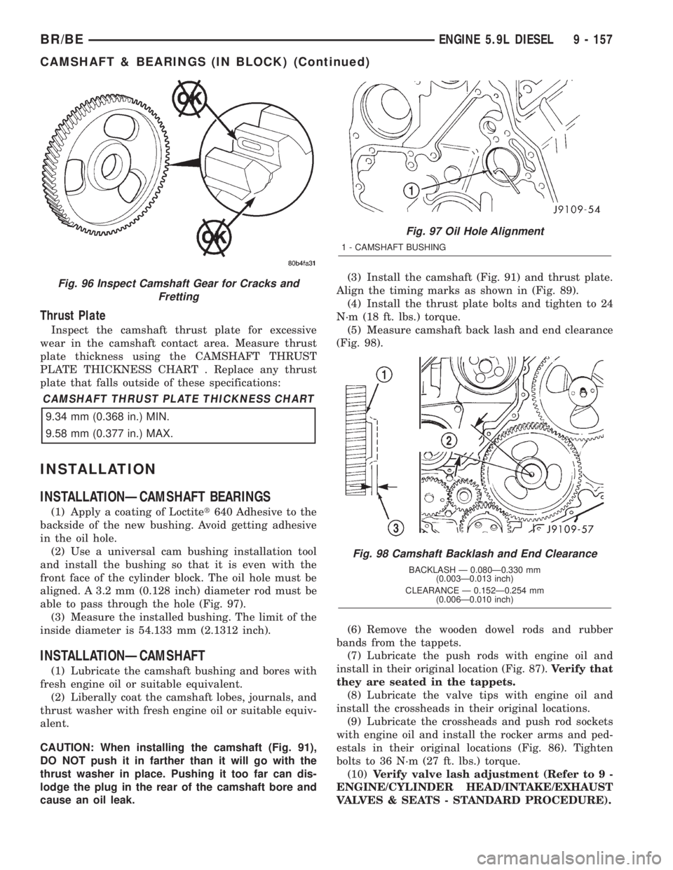
able to pass through the hole (Fig. 97).
(3) Measure the installed bushing. The limit of the
inside diameter is 54.133 mm (2.1312 inch).
INSTALLATIONÐCAMSHAFT
(1) Lubricate the camshaft bushing and bores with
fresh engine oil or suitable equivalent.
(2) Liberally coat the camshaft lobes, journals, and
thrust washer with fresh engine oil or suitable equiv-
alent.
CAUTION: When installing the camshaft (Fig. 91),
DO NOT push it in farther than it will go with the
thrust washer in place. Pushing it too far can dis-
lodge the plug in the rear of the camshaft bore and
cause an oil leak.(3) Install the camshaft (Fig. 91) and thrust plate.
Align the timing marks as shown in (Fig. 89).
(4) Install the thrust plate bolts and tighten to 24
N´m (18 ft. lbs.) torque.
(5) Measure camshaft back lash and end clearance
(Fig. 98).
(6) Remove the wooden dowel rods and rubber
bands from the tappets.
(7) Lubricate the push rods with engine oil and
install in their original location (Fig. 87).Verify that
they are seated in the tappets.
(8) Lubricate the valve tips with engine oil and
install the crossheads in their original locations.
(9) Lubricate the crossheads and push rod sockets
with engine oil and install the rocker arms and ped-
estals in their original locations (Fig. 86). Tighten
bolts to 36 N´m (27 ft. lbs.) torque.
(10)Verify valve lash adjustment (Refer to 9 -
ENGINE/CYLINDER HEAD/INTAKE/EXHAUST
VALVES & SEATS - STANDARD PROCEDURE).
Fig. 96 Inspect Camshaft Gear for Cracks and
Fretting
Fig. 97 Oil Hole Alignment
1 - CAMSHAFT BUSHING
Fig. 98 Camshaft Backlash and End Clearance
BACKLASH Ð 0.080Ð0.330 mm
(0.003Ð0.013 inch)
CLEARANCE Ð 0.152Ð0.254 mm
(0.006Ð0.010 inch)
BR/BEENGINE 5.9L DIESEL 9 - 157
CAMSHAFT & BEARINGS (IN BLOCK) (Continued)
Page 1239 of 2255
(8) Install the oil pan, suction tube and gaskets
(Refer to 9 - ENGINE/LUBRICATION/OIL PAN -
INSTALLATION).
(9) Install the flywheel housing and bolts. Tighten
the bolts to 60 N´m (44 ft. lbs.) torque.
(10) Install the starter motor (Refer to 8 - ELEC-
TRICAL/STARTING/STARTER MOTOR - INSTAL-
LATION).
(11) Install the flywheel or converter drive plate.
Tighten bolts to 137 N´m (101 ft. lbs.)
(12) Install the transmission and transfer case (if
equipped).
(13) Lower vehicle.(14) Fill the crankcase with new engine oil.
(15) Connect the battery negative cables.
(16) Start engine and check for oil leaks.
SOLID LIFTERS/TAPPETS
REMOVAL
NOTE: This procedure requires use of Miller Tool
8502 Tappet Replacement Kit, or Cummins Tool Kit
#3822513.
(1) Remove camshaft (Refer to 9 - ENGINE/EN-
GINE BLOCK/CAMSHAFT & BEARINGS (IN
BLOCK) - REMOVAL).
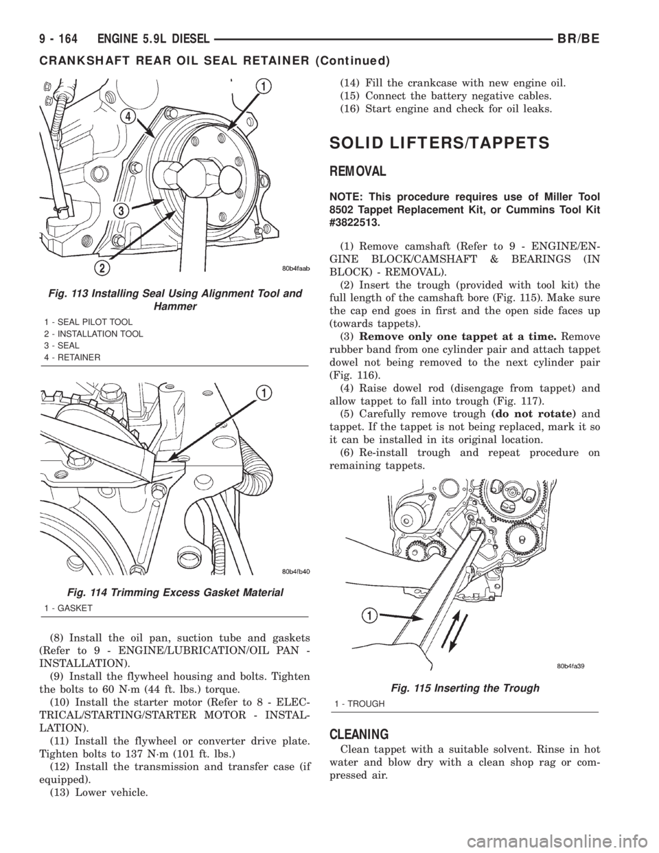
(2) Insert the trough (provided with tool kit) the
full length of the camshaft bore (Fig. 115). Make sure
the cap end goes in first and the open side faces up
(towards tappets).
(3)Remove only one tappet at a time.Remove
rubber band from one cylinder pair and attach tappet
dowel not being removed to the next cylinder pair
(Fig. 116).
(4) Raise dowel rod (disengage from tappet) and
allow tappet to fall into trough (Fig. 117).
(5) Carefully remove trough(do not rotate)and
tappet. If the tappet is not being replaced, mark it so
it can be installed in its original location.
(6) Re-install trough and repeat procedure on
remaining tappets.
CLEANING
Clean tappet with a suitable solvent. Rinse in hot
water and blow dry with a clean shop rag or com-
pressed air.
Fig. 113 Installing Seal Using Alignment Tool and
Hammer
1 - SEAL PILOT TOOL
2 - INSTALLATION TOOL
3 - SEAL
4 - RETAINER
Fig. 114 Trimming Excess Gasket Material
1 - GASKET
Fig. 115 Inserting the Trough
1 - TROUGH
9 - 164 ENGINE 5.9L DIESELBR/BE
CRANKSHAFT REAR OIL SEAL RETAINER (Continued)
Page 1540 of 2255
AUTOMATIC TRANSMISSION - 46RE
TABLE OF CONTENTS
page page
AUTOMATIC TRANSMISSION - 46RE
DESCRIPTION.........................89
OPERATION...........................91
DIAGNOSIS AND TESTING
DIAGNOSIS AND TESTING - AUTOMATIC
TRANSMISSION......................96
DIAGNOSIS AND TESTING - PRELIMINARY . 97
DIAGNOSIS AND TESTING - ROAD
TESTING............................97
DIAGNOSIS AND TESTING - HYDRAULIC
PRESSURE TEST.....................98
DIAGNOSIS AND TESTING - AIR TESTING
TRANSMISSION CLUTCH AND BAND
OPERATION........................100
DIAGNOSIS AND TESTING - CONVERTER
HOUSING FLUID LEAK................101
DIAGNOSIS AND TESTING - DIAGNOSIS
CHARTS...........................102
STANDARD PROCEDURE - ALUMINUM
THREAD REPAIR.....................114
REMOVAL............................114
DISASSEMBLY........................115
CLEANING...........................122
INSPECTION.........................122
ASSEMBLY...........................122
INSTALLATION........................130
SCHEMATICS AND DIAGRAMS
HYDRAULIC SCHEMATICS.............132
SPECIFICATIONS
TRANSMISSION.....................144
SPECIAL TOOLS
RE TRANSMISSION..................146
ACCUMULATOR
DESCRIPTION........................149
OPERATION..........................150
INSPECTION.........................150
BANDS
DESCRIPTION........................150
OPERATION..........................151
ADJUSTMENTS
ADJUSTMENT - BANDS...............151
ELECTRONIC GOVERNOR
DESCRIPTION........................152
OPERATION..........................153
REMOVAL............................154
INSTALLATION........................154
EXTENSION HOUSING BUSHING
REMOVAL............................156
INSTALLATION........................156EXTENSION HOUSING SEAL
REMOVAL............................156
INSTALLATION........................156
FLUID AND FILTER
DIAGNOSIS AND TESTING
DIAGNOSIS AND TESTING - EFFECTS OF
INCORRECT FLUID LEVEL.............157
DIAGNOSIS AND TESTING - CAUSES OF
BURNT FLUID.......................157
DIAGNOSIS AND TESTING - FLUID
CONTAMINATION....................157
STANDARD PROCEDURE
STANDARD PROCEDURE - FLUID LEVEL
CHECK............................157
STANDARD PROCEDURE - FLUID AND
FILTER REPLACEMENT...............158
STANDARD PROCEDURE - TRANSMISSION
FILL...............................160
FRONT CLUTCH
DESCRIPTION........................160
OPERATION..........................160
DISASSEMBLY........................161
INSPECTION.........................162
ASSEMBLY...........................162
FRONT SERVO
DESCRIPTION........................164
OPERATION..........................164
DISASSEMBLY........................164
CLEANING...........................164
INSPECTION.........................164
ASSEMBLY...........................164
OIL PUMP
DESCRIPTION........................166
OPERATION..........................166
STANDARD PROCEDURE - OIL PUMP
VOLUME CHECK.....................166
DISASSEMBLY........................167
CLEANING...........................168
INSPECTION.........................168
ASSEMBLY...........................169
OUTPUT SHAFT FRONT BEARING
REMOVAL............................171
INSTALLATION........................171
OUTPUT SHAFT REAR BEARING
REMOVAL............................171
INSTALLATION........................172
OVERDRIVE CLUTCH
DESCRIPTION........................172
OPERATION..........................172
BR/BEAUTOMATIC TRANSMISSION - 46RE 21 - 87
Page 1542 of 2255
AUTOMATIC TRANSMISSION -
46RE
DESCRIPTION
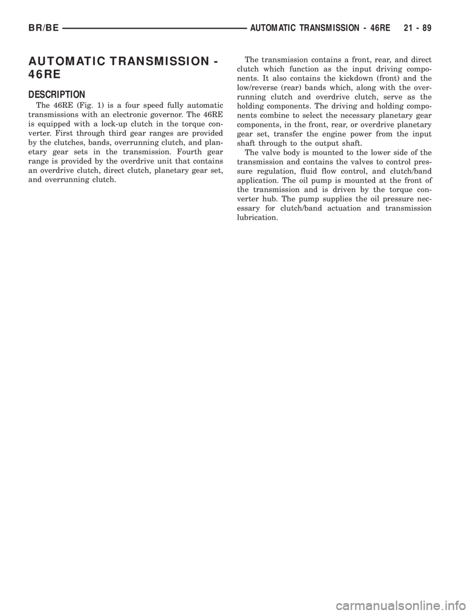
The 46RE (Fig. 1) is a four speed fully automatic
transmissions with an electronic governor. The 46RE
is equipped with a lock-up clutch in the torque con-
verter. First through third gear ranges are provided
by the clutches, bands, overrunning clutch, and plan-
etary gear sets in the transmission. Fourth gear
range is provided by the overdrive unit that contains
an overdrive clutch, direct clutch, planetary gear set,
and overrunning clutch.The transmission contains a front, rear, and direct
clutch which function as the input driving compo-
nents. It also contains the kickdown (front) and the
low/reverse (rear) bands which, along with the over-
running clutch and overdrive clutch, serve as the
holding components. The driving and holding compo-
nents combine to select the necessary planetary gear
components, in the front, rear, or overdrive planetary
gear set, transfer the engine power from the input
shaft through to the output shaft.
The valve body is mounted to the lower side of the
transmission and contains the valves to control pres-
sure regulation, fluid flow control, and clutch/band
application. The oil pump is mounted at the front of
the transmission and is driven by the torque con-
verter hub. The pump supplies the oil pressure nec-
essary for clutch/band actuation and transmission
lubrication.
BR/BEAUTOMATIC TRANSMISSION - 46RE 21 - 89
Page 1544 of 2255
IDENTIFICATION
Transmission identification numbers are stamped
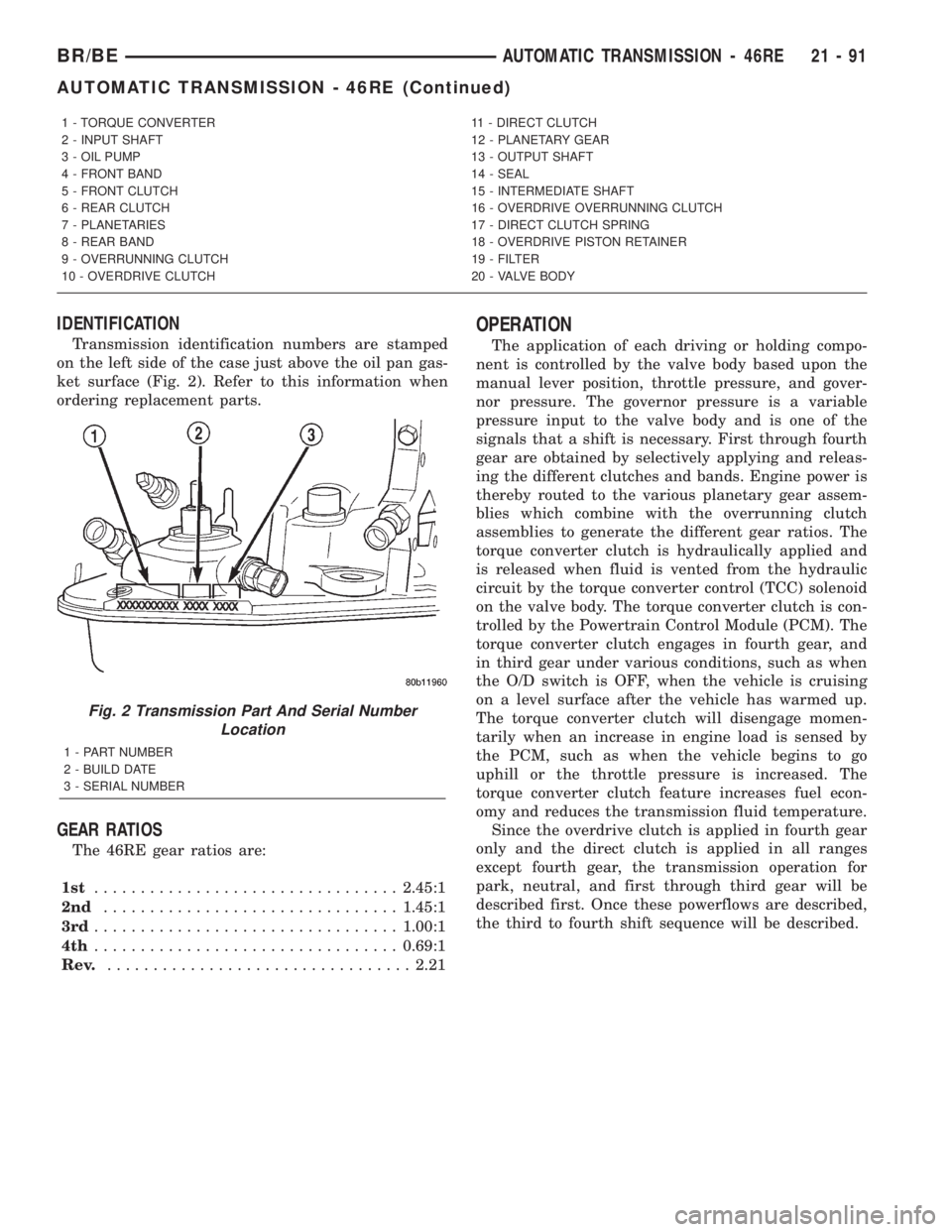
on the left side of the case just above the oil pan gas-
ket surface (Fig. 2). Refer to this information when
ordering replacement parts.
GEAR RATIOS
The 46RE gear ratios are:
1st.................................2.45:1
2nd................................1.45:1
3rd.................................1.00:1
4th.................................0.69:1
Rev..................................2.21
OPERATION
The application of each driving or holding compo-
nent is controlled by the valve body based upon the
manual lever position, throttle pressure, and gover-
nor pressure. The governor pressure is a variable
pressure input to the valve body and is one of the
signals that a shift is necessary. First through fourth
gear are obtained by selectively applying and releas-
ing the different clutches and bands. Engine power is
thereby routed to the various planetary gear assem-
blies which combine with the overrunning clutch
assemblies to generate the different gear ratios. The
torque converter clutch is hydraulically applied and
is released when fluid is vented from the hydraulic
circuit by the torque converter control (TCC) solenoid
on the valve body. The torque converter clutch is con-
trolled by the Powertrain Control Module (PCM). The
torque converter clutch engages in fourth gear, and
in third gear under various conditions, such as when
the O/D switch is OFF, when the vehicle is cruising
on a level surface after the vehicle has warmed up.
The torque converter clutch will disengage momen-
tarily when an increase in engine load is sensed by
the PCM, such as when the vehicle begins to go
uphill or the throttle pressure is increased. The
torque converter clutch feature increases fuel econ-
omy and reduces the transmission fluid temperature.
Since the overdrive clutch is applied in fourth gear
only and the direct clutch is applied in all ranges
except fourth gear, the transmission operation for
park, neutral, and first through third gear will be
described first. Once these powerflows are described,
the third to fourth shift sequence will be described.
1 - TORQUE CONVERTER 11 - DIRECT CLUTCH
2 - INPUT SHAFT 12 - PLANETARY GEAR
3 - OIL PUMP 13 - OUTPUT SHAFT
4 - FRONT BAND 14 - SEAL
5 - FRONT CLUTCH 15 - INTERMEDIATE SHAFT
6 - REAR CLUTCH 16 - OVERDRIVE OVERRUNNING CLUTCH
7 - PLANETARIES 17 - DIRECT CLUTCH SPRING
8 - REAR BAND 18 - OVERDRIVE PISTON RETAINER
9 - OVERRUNNING CLUTCH 19 - FILTER
10 - OVERDRIVE CLUTCH 20 - VALVE BODY
Fig. 2 Transmission Part And Serial Number
Location
1 - PART NUMBER
2 - BUILD DATE
3 - SERIAL NUMBER
BR/BEAUTOMATIC TRANSMISSION - 46RE 21 - 91
AUTOMATIC TRANSMISSION - 46RE (Continued)
Page 1545 of 2255
PARK POWERFLOW
As the engine is running and the crankshaft is
rotating, the flexplate and torque converter, which
are also bolted to it, are all rotating in a clockwise
direction as viewed from the front of the engine. The
notched hub of the torque converter is connected to
the oil pump's internal gear, supplying the transmis-
sion with oil pressure. As the converter turns, it
turns the input shaft in a clockwise direction. As the
input shaft is rotating, the front clutch hub-rear
clutch retainer and all their associated parts are also
rotating, all being directly connected to the input
shaft. The power flow from the engine through the
front clutch hub and rear clutch retainer stops at the
rear clutch retainer. Therefore, no power flow to the
output shaft occurs because no clutches are applied.
The only mechanism in use at this time is the park-
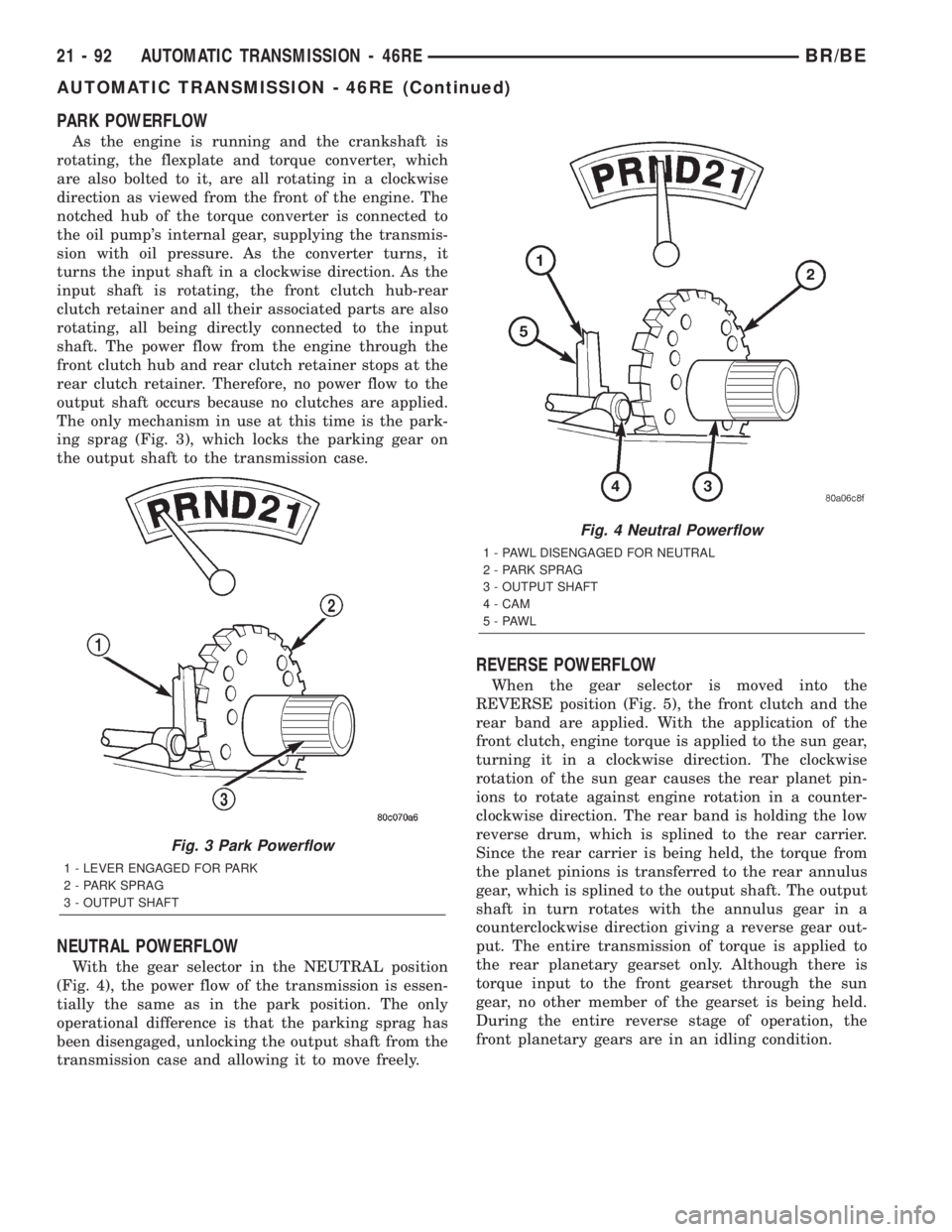
ing sprag (Fig. 3), which locks the parking gear on
the output shaft to the transmission case.
NEUTRAL POWERFLOW
With the gear selector in the NEUTRAL position
(Fig. 4), the power flow of the transmission is essen-
tially the same as in the park position. The only
operational difference is that the parking sprag has
been disengaged, unlocking the output shaft from the
transmission case and allowing it to move freely.
REVERSE POWERFLOW
When the gear selector is moved into the
REVERSE position (Fig. 5), the front clutch and the
rear band are applied. With the application of the
front clutch, engine torque is applied to the sun gear,
turning it in a clockwise direction. The clockwise
rotation of the sun gear causes the rear planet pin-
ions to rotate against engine rotation in a counter-
clockwise direction. The rear band is holding the low
reverse drum, which is splined to the rear carrier.
Since the rear carrier is being held, the torque from
the planet pinions is transferred to the rear annulus
gear, which is splined to the output shaft. The output
shaft in turn rotates with the annulus gear in a
counterclockwise direction giving a reverse gear out-
put. The entire transmission of torque is applied to
the rear planetary gearset only. Although there is
torque input to the front gearset through the sun
gear, no other member of the gearset is being held.
During the entire reverse stage of operation, the
front planetary gears are in an idling condition.
Fig. 3 Park Powerflow
1 - LEVER ENGAGED FOR PARK
2 - PARK SPRAG
3 - OUTPUT SHAFT
Fig. 4 Neutral Powerflow
1 - PAWL DISENGAGED FOR NEUTRAL
2 - PARK SPRAG
3 - OUTPUT SHAFT
4 - CAM
5-PAWL
21 - 92 AUTOMATIC TRANSMISSION - 46REBR/BE
AUTOMATIC TRANSMISSION - 46RE (Continued)
Page 1546 of 2255
FIRST GEAR POWERFLOW
When the gearshift lever is moved into the DRIVE
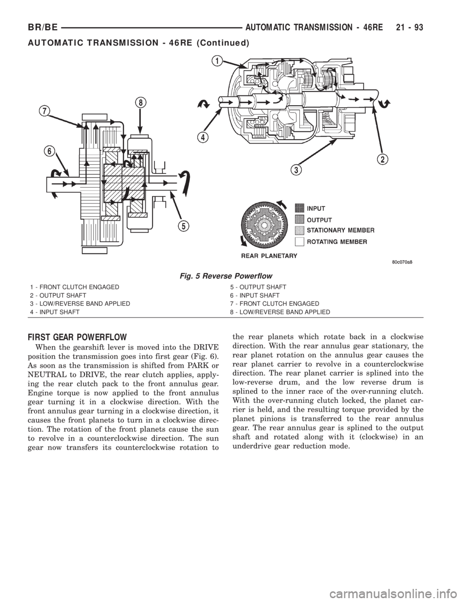
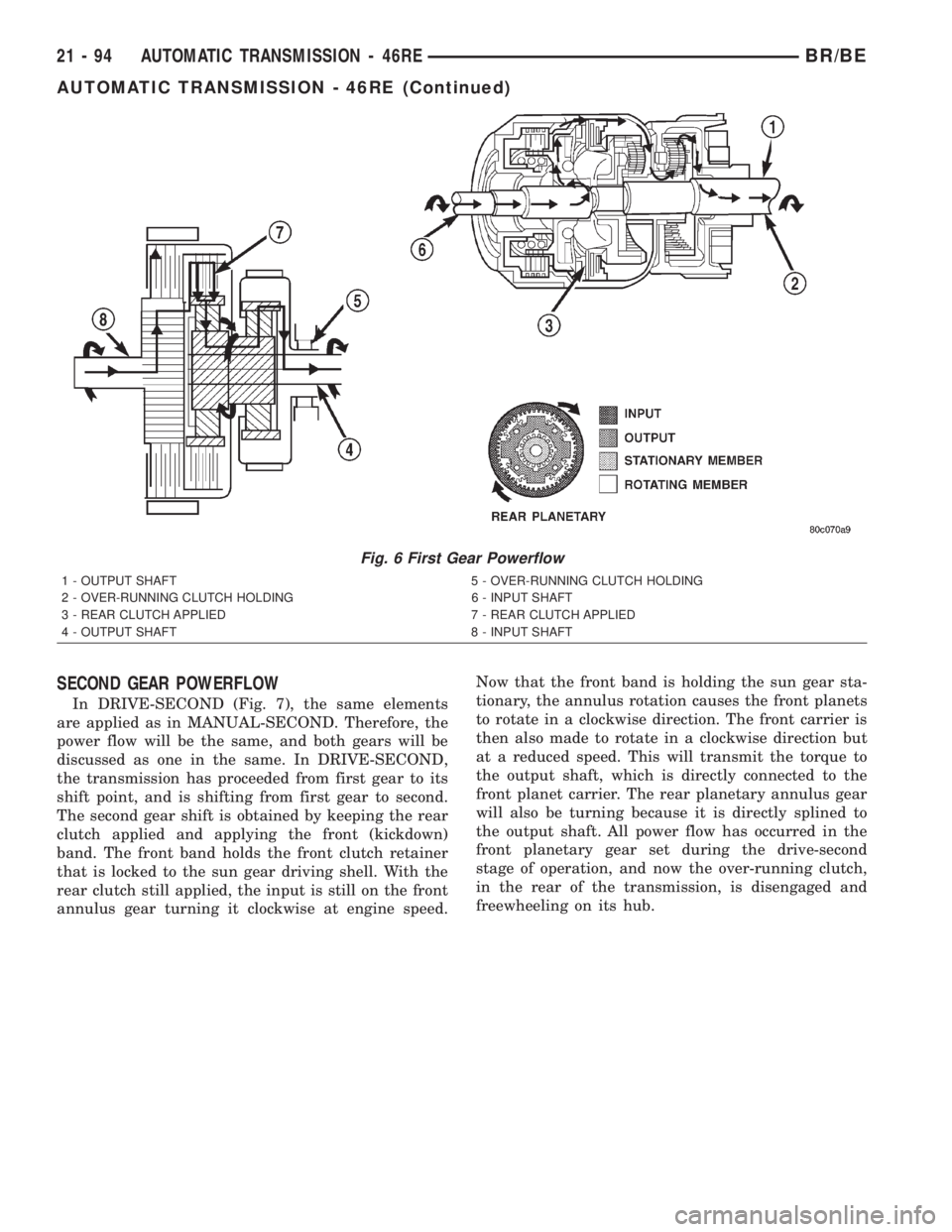
position the transmission goes into first gear (Fig. 6).
As soon as the transmission is shifted from PARK or
NEUTRAL to DRIVE, the rear clutch applies, apply-
ing the rear clutch pack to the front annulus gear.
Engine torque is now applied to the front annulus
gear turning it in a clockwise direction. With the
front annulus gear turning in a clockwise direction, it
causes the front planets to turn in a clockwise direc-
tion. The rotation of the front planets cause the sun
to revolve in a counterclockwise direction. The sun
gear now transfers its counterclockwise rotation tothe rear planets which rotate back in a clockwise
direction. With the rear annulus gear stationary, the
rear planet rotation on the annulus gear causes the
rear planet carrier to revolve in a counterclockwise
direction. The rear planet carrier is splined into the
low-reverse drum, and the low reverse drum is
splined to the inner race of the over-running clutch.
With the over-running clutch locked, the planet car-
rier is held, and the resulting torque provided by the
planet pinions is transferred to the rear annulus
gear. The rear annulus gear is splined to the output
shaft and rotated along with it (clockwise) in an
underdrive gear reduction mode.
Fig. 5 Reverse Powerflow
1 - FRONT CLUTCH ENGAGED 5 - OUTPUT SHAFT
2 - OUTPUT SHAFT 6 - INPUT SHAFT
3 - LOW/REVERSE BAND APPLIED 7 - FRONT CLUTCH ENGAGED
4 - INPUT SHAFT 8 - LOW/REVERSE BAND APPLIED
BR/BEAUTOMATIC TRANSMISSION - 46RE 21 - 93
AUTOMATIC TRANSMISSION - 46RE (Continued)
Page 1547 of 2255
SECOND GEAR POWERFLOW
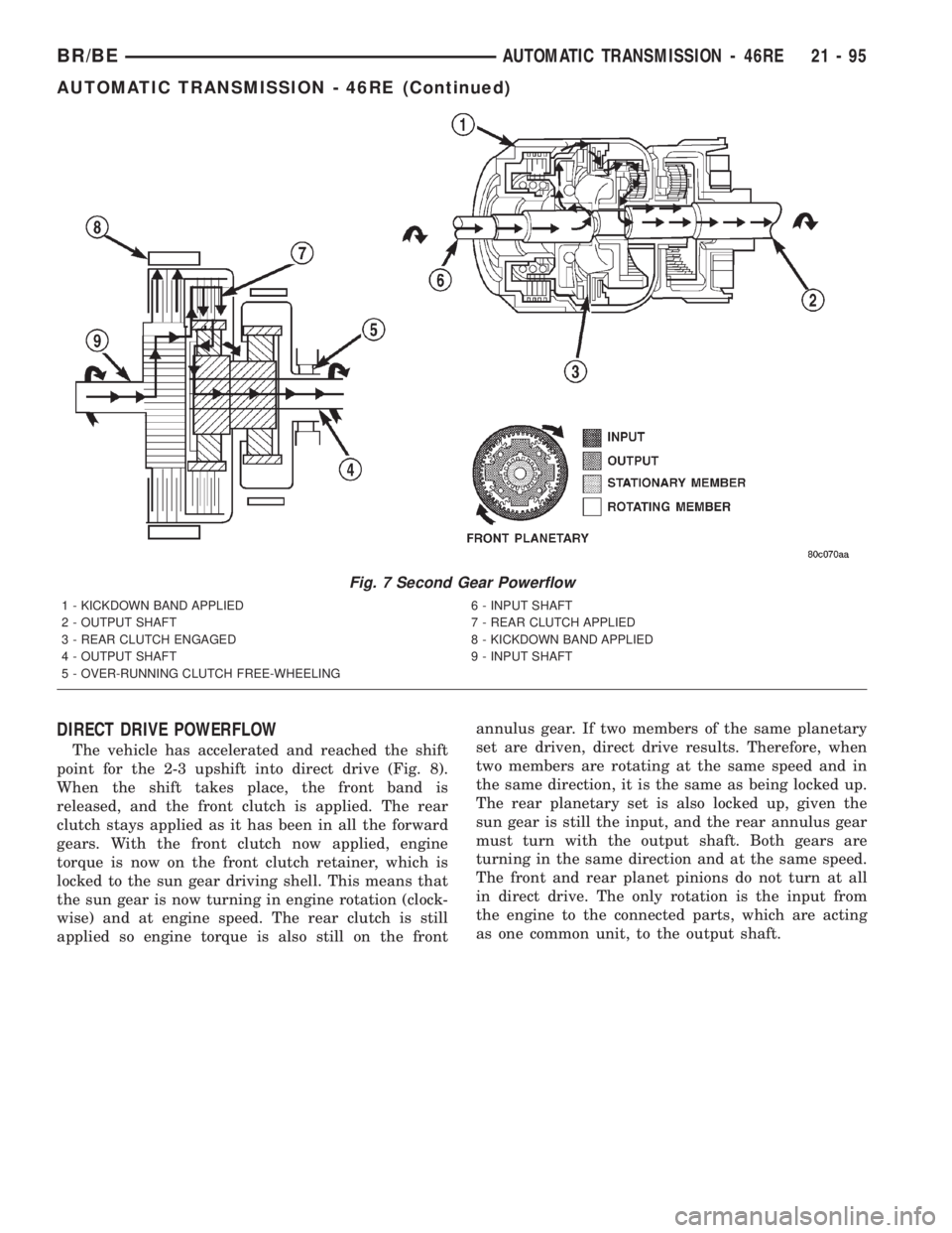
In DRIVE-SECOND (Fig. 7), the same elements
are applied as in MANUAL-SECOND. Therefore, the
power flow will be the same, and both gears will be
discussed as one in the same. In DRIVE-SECOND,
the transmission has proceeded from first gear to its
shift point, and is shifting from first gear to second.
The second gear shift is obtained by keeping the rear
clutch applied and applying the front (kickdown)
band. The front band holds the front clutch retainer
that is locked to the sun gear driving shell. With the
rear clutch still applied, the input is still on the front
annulus gear turning it clockwise at engine speed.Now that the front band is holding the sun gear sta-
tionary, the annulus rotation causes the front planets
to rotate in a clockwise direction. The front carrier is
then also made to rotate in a clockwise direction but
at a reduced speed. This will transmit the torque to
the output shaft, which is directly connected to the
front planet carrier. The rear planetary annulus gear
will also be turning because it is directly splined to
the output shaft. All power flow has occurred in the
front planetary gear set during the drive-second
stage of operation, and now the over-running clutch,
in the rear of the transmission, is disengaged and
freewheeling on its hub.
Fig. 6 First Gear Powerflow
1 - OUTPUT SHAFT 5 - OVER-RUNNING CLUTCH HOLDING
2 - OVER-RUNNING CLUTCH HOLDING 6 - INPUT SHAFT
3 - REAR CLUTCH APPLIED 7 - REAR CLUTCH APPLIED
4 - OUTPUT SHAFT 8 - INPUT SHAFT
21 - 94 AUTOMATIC TRANSMISSION - 46REBR/BE
AUTOMATIC TRANSMISSION - 46RE (Continued)
Page 1548 of 2255
DIRECT DRIVE POWERFLOW
The vehicle has accelerated and reached the shift
point for the 2-3 upshift into direct drive (Fig. 8).
When the shift takes place, the front band is
released, and the front clutch is applied. The rear
clutch stays applied as it has been in all the forward
gears. With the front clutch now applied, engine
torque is now on the front clutch retainer, which is
locked to the sun gear driving shell. This means that
the sun gear is now turning in engine rotation (clock-
wise) and at engine speed. The rear clutch is still
applied so engine torque is also still on the frontannulus gear. If two members of the same planetary
set are driven, direct drive results. Therefore, when
two members are rotating at the same speed and in
the same direction, it is the same as being locked up.
The rear planetary set is also locked up, given the
sun gear is still the input, and the rear annulus gear
must turn with the output shaft. Both gears are
turning in the same direction and at the same speed.
The front and rear planet pinions do not turn at all
in direct drive. The only rotation is the input from
the engine to the connected parts, which are acting
as one common unit, to the output shaft.
Fig. 7 Second Gear Powerflow
1 - KICKDOWN BAND APPLIED 6 - INPUT SHAFT
2 - OUTPUT SHAFT 7 - REAR CLUTCH APPLIED
3 - REAR CLUTCH ENGAGED 8 - KICKDOWN BAND APPLIED
4 - OUTPUT SHAFT 9 - INPUT SHAFT
5 - OVER-RUNNING CLUTCH FREE-WHEELING
BR/BEAUTOMATIC TRANSMISSION - 46RE 21 - 95
AUTOMATIC TRANSMISSION - 46RE (Continued)