catalytic converter DODGE RAM 2002 Service Repair Manual
[x] Cancel search | Manufacturer: DODGE, Model Year: 2002, Model line: RAM, Model: DODGE RAM 2002Pages: 2255, PDF Size: 62.07 MB
Page 16 of 2255
²The use of leaded gas is prohibited by Federal
law. Using leaded gasoline can impair engine perfor-
mance, damage the emission control system, and
could result in loss of warranty coverage.
²An out-of-tune engine, or certain fuel or ignition
malfunctions, can cause the catalytic converter to
overheat. If you notice a pungent burning odor or
some light smoke, your engine may be out of tune or
malfunctioning and may require immediate service.
Contact your dealer for service assistance.
²When pulling a heavy load or driving a fully
loaded vehicle when the humidity is low and the tem-
perature is high, use a premium unleaded fuel to
help prevent spark knock. If spark knock persists,
lighten the load, or engine piston damage may result.
²The use of fuel additives which are now being
sold as octane enhancers is not recommended. Most
of these products contain high concentrations of
methanol. Fuel system damage or vehicle perfor-
mance problems resulting from the use of such fuels
or additives is not the responsibility of
DaimlerChrysler Corporation and may not be covered
under the new vehicle warranty.
NOTE: Intentional tampering with emissions control
systems can result in civil penalties being assessed
against you.
DESCRIPTION - FUEL REQUIREMENTS -
DIESEL ENGINE
DESCRIPTION
WARNING: Do not use alcohol or gasoline as a fuel
blending agent. They can be unstable under certain
conditions and hazardous or explosive when mixed
with diesel fuel.
Use good quality diesel fuel from a reputable sup-
plier in your Dodge truck. For most year-round ser-
vice, number 2 diesel fuel meeting ASTM
specification D-975 will provide good performance. If
the vehicle is exposed to extreme cold (below 0ÉF/-
18ÉC), or is required to operate at colder-than-normal
conditions for prolonged periods, use climatized No. 2
diesel fuel or dilute the No. 2 diesel fuel with 50%
No. 1 diesel fuel. This will provide better protection
from fuel gelling or wax-plugging of the fuel filters.
Diesel fuel is seldom completely free of water. To
prevent fuel system trouble, including fuel line freez-
ing in winter, drain the accumulated water from the
fuel/water separator using the fuel/water separator
drain provided. If you buy good-quality fuel and fol-
low the cold-weather advice above, fuel conditioners
should not be required in your vehicle. If available in
your area, a high cetane ªpremiumº diesel fuel mayoffer improved cold starting and warm-up perfor-
mance.
DESCRIPTION - ENGINE COOLANT
WARNING: ANTIFREEZE IS AN ETHYLENE GLYCOL
BASE COOLANT AND IS HARMFUL IF SWAL-
LOWED OR INHALED. IF SWALLOWED, DRINK
TWO GLASSES OF WATER AND INDUCE VOMIT-
ING. IF INHALED, MOVE TO FRESH AIR AREA.
SEEK MEDICAL ATTENTION IMMEDIATELY. DO NOT
STORE IN OPEN OR UNMARKED CONTAINERS.
WASH SKIN AND CLOTHING THOROUGHLY AFTER
COMING IN CONTACT WITH ETHYLENE GLYCOL.
KEEP OUT OF REACH OF CHILDREN. DISPOSE OF
GLYCOL BASE COOLANT PROPERLY, CONTACT
YOUR DEALER OR GOVERNMENT AGENCY FOR
LOCATION OF COLLECTION CENTER IN YOUR
AREA. DO NOT OPEN A COOLING SYSTEM WHEN
THE ENGINE IS AT OPERATING TEMPERATURE OR
HOT UNDER PRESSURE, PERSONAL INJURY CAN
RESULT. AVOID RADIATOR COOLING FAN WHEN
ENGINE COMPARTMENT RELATED SERVICE IS
PERFORMED, PERSONAL INJURY CAN RESULT.
CAUTION: Use of Propylene Glycol based coolants
is not recommended, as they provide less freeze
protection and less corrosion protection.
The cooling system is designed around the coolant.
The coolant must accept heat from engine metal, in
the cylinder head area near the exhaust valves and
engine block. Then coolant carries the heat to the
radiator where the tube/fin radiator can transfer the
heat to the air.
The use of aluminum cylinder blocks, cylinder
heads, and water pumps requires special corrosion
protection. MopartAntifreeze/Coolant, 5
Year/100,000 Mile Formula (MS-9769), or the equiva-
lent ethylene glycol base coolant with organic corro-
sion inhibitors (called HOAT, for Hybrid Organic
Additive Technology) is recommended. This coolant
offers the best engine cooling without corrosion when
mixed with 50% Ethylene Glycol and 50% distilled
water to obtain a freeze point of -37ÉC (-35ÉF). If it
loses color or becomes contaminated, drain, flush,
and replace with fresh properly mixed coolant solu-
tion.
CAUTION: MoparTAntifreeze/Coolant, 5
Year/100,000 Mile Formula (MS-9769) may not be
mixed with any other type of antifreeze. Mixing of
coolants other than specified (non-HOAT or other
HOAT), may result in engine damage that may not
be covered under the new vehicle warranty, and
decreased corrosion protection.
BR/BELUBRICATION & MAINTENANCE 0 - 3
FLUID TYPES (Continued)
Page 255 of 2255
hoses, gasket edges and heater. Seal small leak holes
with a Sealer Lubricant (or equivalent). Repair leak
holes and inspect system again with pressure
applied.
Drops Quickly:Indicates that serious leakage is
occurring. Examine system for external leakage. If
leaks are not visible, inspect for internal leakage.
Large radiator leak holes should be repaired by a
reputable radiator repair shop.
INTERNAL LEAKAGE INSPECTION
Remove engine oil pan drain plug and drain a
small amount of engine oil. If coolant is present in
the pan, it will drain first because it is heavier than
oil. An alternative method is to operate engine for a
short period to churn the oil. After this is done,
remove engine dipstick and inspect for water glob-
ules. Also inspect transmission dipstick for water
globules and transmission fluid cooler for leakage.
WARNING: WITH RADIATOR PRESSURE TESTER
TOOL INSTALLED ON RADIATOR, DO NOT ALLOW
PRESSURE TO EXCEED 110 KPA (20 PSI). PRES-
SURE WILL BUILD UP QUICKLY IF A COMBUSTION
LEAK IS PRESENT. TO RELEASE PRESSURE,
ROCK TESTER FROM SIDE TO SIDE. WHEN
REMOVING TESTER, DO NOT TURN TESTER MORE
THAN 1/2 TURN IF SYSTEM IS UNDER PRESSURE.
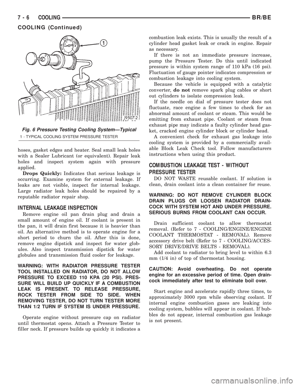
Operate engine without pressure cap on radiator
until thermostat opens. Attach a Pressure Tester to
filler neck. If pressure builds up quickly it indicates acombustion leak exists. This is usually the result of a
cylinder head gasket leak or crack in engine. Repair
as necessary.
If there is not an immediate pressure increase,
pump the Pressure Tester. Do this until indicated
pressure is within system range of 110 kPa (16 psi).
Fluctuation of gauge pointer indicates compression or
combustion leakage into cooling system.
Because the vehicle is equipped with a catalytic
converter,do notremove spark plug cables or short
out cylinders to isolate compression leak.
If the needle on dial of pressure tester does not
fluctuate, race engine a few times to check for an
abnormal amount of coolant or steam. This would be
emitting from exhaust pipe. Coolant or steam from
exhaust pipe may indicate a faulty cylinder head gas-
ket, cracked engine cylinder block or cylinder head.
A convenient check for exhaust gas leakage into
cooling system is provided by a commercially avail-
able Block Leak Check tool. Follow manufacturers
instructions when using this product.
COMBUSTION LEAKAGE TEST - WITHOUT
PRESSURE TESTER
DO NOT WASTE reusable coolant. If solution is
clean, drain coolant into a clean container for reuse.
WARNING: DO NOT REMOVE CYLINDER BLOCK
DRAIN PLUGS OR LOOSEN RADIATOR DRAIN-
COCK WITH SYSTEM HOT AND UNDER PRESSURE.
SERIOUS BURNS FROM COOLANT CAN OCCUR.
Drain sufficient coolant to allow thermostat
removal. (Refer to 7 - COOLING/ENGINE/ENGINE
COOLANT THERMOSTAT - REMOVAL). Remove
accessory drive belt (Refer to 7 - COOLING/ACCES-
SORY DRIVE/DRIVE BELTS - REMOVAL).
Add coolant to radiator to bring level to within 6.3
mm (1/4 in) of top of thermostat housing.
CAUTION: Avoid overheating. Do not operate
engine for an excessive period of time. Open drain-
cock immediately after test to eliminate boil over.
Start engine and accelerate rapidly three times, to
approximately 3000 rpm while observing coolant. If
internal engine combustion gases are leaking into
cooling system, bubbles will appear in coolant. If bub-
bles do not appear, internal combustion gas leakage
is not present.
Fig. 6 Pressure Testing Cooling SystemÐTypical
1 - TYPICAL COOLING SYSTEM PRESSURE TESTER
7 - 6 COOLINGBR/BE
COOLING (Continued)
Page 478 of 2255
CAUTION: Do not leave any one spark plug cable
disconnected for longer than necessary during test-
ing. This may cause possible heat damage to the
catalytic converter. Total test time must not exceed
ten minutes.
With the engine running, remove spark plug cable
from spark plug (one at a time) and hold next to a
good engine ground. If the cable and spark plug are
in good condition, the engine rpm should drop and
the engine will run poorly. If engine rpm does not
drop, the cable and/or spark plug may not be operat-
ing properly and should be replaced. Also check
engine cylinder compression.
With the engine not running, connect one end of a
test probe to a good ground. Start the engine and run
the other end of the test probe along the entire
length of all spark plug cables. If cables are cracked
or punctured, there will be a noticeable spark jump
from the damaged area to the test probe. The cable
running from the ignition coil to the distributor cap
can be checked in the same manner. Cracked, dam-
aged or faulty cables should be replaced with resis-
tance type cable. This can be identified by the words
ELECTRONIC SUPPRESSION printed on the cable
jacket.
Use an ohmmeter to test for open circuits, exces-
sive resistance or loose terminals. If equipped,
remove the distributor cap from the distributor.Do
not remove cables from cap.Remove cable from
spark plug. Connect ohmmeter to spark plug termi-
nal end of cable and to corresponding electrode in
distributor cap. Resistance should be 250 to 1000
Ohms per inch of cable. If not, remove cable from dis-
tributor cap tower and connect ohmmeter to the ter-
minal ends of cable. If resistance is not within
specifications as found in the SPARK PLUG CABLE
RESISTANCE chart, replace the cable. Test all spark
plug cables in this manner.
SPARK PLUG CABLE RESISTANCE
MINIMUM MAXIMUM
250 Ohms Per Inch 1000 Ohms Per Inch
3000 Ohms Per Foot 12,000 Ohms Per Foot
To test ignition coil-to-distributor cap cable, do not
remove the cable from the cap. Connect ohmmeter to
rotor button (center contact) of distributor cap and
terminal at ignition coil end of cable. If resistance is
not within specifications as found in the Spark Plug
Cable Resistance chart, remove the cable from the
distributor cap. Connect the ohmmeter to the termi-
nal ends of the cable. If resistance is not within spec-
ifications as found in the Spark Plug CableResistance chart, replace the cable. Inspect the igni-
tion coil tower for cracks, burns or corrosion.
REMOVAL
CAUTION: When disconnecting a high voltage cable
from a spark plug or from the distributor cap, twist
the rubber boot slightly (1/2 turn) to break it loose
(Fig. 37). Grasp the boot (not the cable) and pull it
off with a steady, even force.
INSTALLATION
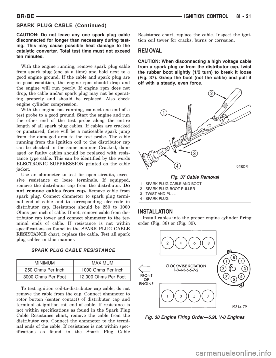
Install cables into the proper engine cylinder firing
order (Fig. 38) or (Fig. 39).
Fig. 37 Cable Removal
1 - SPARK PLUG CABLE AND BOOT
2 - SPARK PLUG BOOT PULLER
3 - TWIST AND PULL
4 - SPARK PLUG
Fig. 38 Engine Firing OrderÐ5.9L V-8 Engines
BR/BEIGNITION CONTROL 8I - 21
SPARK PLUG CABLE (Continued)
Page 1023 of 2255
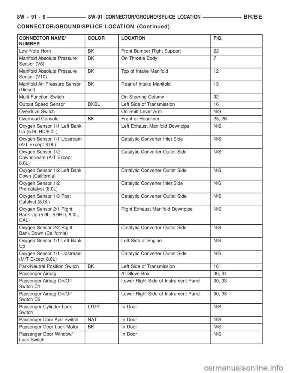
CONNECTOR NAME/
NUMBERCOLOR LOCATION FIG.
Low Note Horn BK Front Bumper Right Support 22
Manifold Absolute Pressure
Sensor (V8)BK On Throttle Body 7
Manifold Absolute Pressure
Sensor (V10)BK Top of Intake Manifold 12
Manifold Air Pressure Sensor
(Diesel)BK Rear of Intake Manifold 13
Multi-Function Switch On Steering Column 32
Output Speed Sensor DKBL Left Side of Transmission 16
Overdrive Switch On Shift Lever Arm N/S
Overhead Console BK Front of Headliner 25, 26
Oxygen Sensor 1/1 Left Bank
Up (5.9L HD/8.0L)Left Exhaust Manifold Downpipe N/S
Oxygen Sensor 1/1 Upstream
(A/T Except 8.0L)Catalytic Converter Inlet Side N/S
Oxygen Sensor 1/2
Downstream (A/T Except
8.0L)Catalytic Converter Outlet Side N/S
Oxygen Sensor 1/2 Left Bank
Down (California)Catalytic Converter Outlet Side N/S
Oxygen Sensor 1/2
Pre-catalyst (8.0L)Catalytic Converter Inlet Side N/S
Oxygen Sensor 1/3 Post
Catalyst (8.0L)Catalytic Converter Outlet Side N/S
Oxygen Sensor 2/1 Right
Bank Up (5.9L, 5.9HD, 8.0L,
CAL)Right Exhaust Manifold Downpipe N/S
Oxygen Sensor 2/2 Right
Bank Down (California)Catalytic Converter Outlet Side N/S
Oxygen Sensor 1/1 Left Bank
UpLeft Side of Engine N/S
Oxygen Sensor 1/1 Upstream
(M/T Except 8.0L)Catalytic Converter Outlet Side N/S
Park/Neutral Position Switch BK Left Side of Transmission 16
Passenger Airbag At Glove Box 30, 34
Passenger Airbag On/Off
Switch C1Lower Right Side of Instrument Panel 30, 33
Passenger Airbag On/Off
Switch C2Lower Right Side of Instrument Panel 30, 33
Passenger Cylinder Lock
SwitchLTGY In Door N/S
Passenger Door Ajar Switch NAT In Door N/S
Passenger Door Lock Motor BK In Door N/S
Passenger Door Window/
Lock SwitchIn Door N/S
8W - 91 - 6 8W-91 CONNECTOR/GROUND/SPLICE LOCATIONBR/BE
CONNECTOR/GROUND/SPLICE LOCATION (Continued)
Page 1268 of 2255
EXHAUST SYSTEM
TABLE OF CONTENTS
page page
EXHAUST SYSTEM
DESCRIPTION
DESCRIPTION - 5.9/8.0L.................2
DESCRIPTIONÐ5.9L DIESEL.............3
DIAGNOSIS AND TESTING
DIAGNOSIS AND TESTING - GAS ENGINE . . . 4
DIAGNOSIS AND TESTING - DIESEL
ENGINE..............................4
SPECIFICATIONS
TORQUE.............................5
CATALYTIC CONVERTER - 3.9L/5.2L/5.9L
DESCRIPTION..........................5
OPERATION............................5
REMOVAL.............................5
INSPECTION...........................6
INSTALLATION..........................6
CATALYTIC CONVERTER - 5.9L HD/8.0L
DESCRIPTION..........................6
OPERATION............................6
REMOVAL.............................6
INSPECTION...........................6
INSTALLATION..........................7
EXHAUST PIPE - 3.9L/5.2L/5.9L
REMOVAL.............................7
INSPECTION...........................7
INSTALLATION..........................7
EXHAUST PIPE - 5.9L HD/8.0L
REMOVAL.............................7
INSPECTION...........................8
INSTALLATION..........................8
EXHAUST PIPE - 5.9L DIESEL
REMOVAL.............................9
INSPECTION...........................9
INSTALLATION..........................9
HEAT SHIELDS
DESCRIPTION.........................10
REMOVAL.............................10
INSTALLATION.........................10
MUFFLER - 3.9L/5.2L/5.9L/8.0L
REMOVAL.............................10INSTALLATION.........................10
MUFFLER - 5.9L DIESEL
REMOVAL.............................11
INSTALLATION.........................11
TAILPIPE - 3.9L/5.2L/5.9L
REMOVAL.............................11
INSPECTION..........................11
INSTALLATION.........................11
TAILPIPE - 5.9L HD/8.0L
REMOVAL.............................12
INSPECTION..........................12
INSTALLATION.........................12
TAILPIPE - 5.9L DIESEL
REMOVAL.............................12
INSPECTION..........................12
INSTALLATION.........................13
RESONATOR
REMOVAL.............................13
INSTALLATION.........................13
TURBOCHARGER SYSTEM
DIAGNOSIS AND TESTING -
TURBOCHARGER BOOST PRESSURE.....13
TURBOCHARGER
DESCRIPTION.........................14
OPERATION...........................14
REMOVAL.............................15
CLEANING............................16
INSPECTION..........................16
INSTALLATION.........................17
CHARGE AIR COOLER AND PLUMBING
DESCRIPTION.........................18
OPERATION...........................18
DIAGNOSIS AND TESTING - CHARGE AIR
COOLER SYSTEM - LEAKS..............18
REMOVAL.............................18
CLEANING............................19
INSPECTION..........................19
INSTALLATION.........................20
BR/BEEXHAUST SYSTEM 11 - 1
Page 1269 of 2255
EXHAUST SYSTEM
DESCRIPTION
DESCRIPTION - 5.9/8.0L
CAUTION: Avoid application of rust prevention com-
pounds or undercoating materials to exhaust sys-
tem floor pan exhaust heat shields. Light overspray
near the edges is permitted. Application of coating
will result in excessive floor pan temperatures and
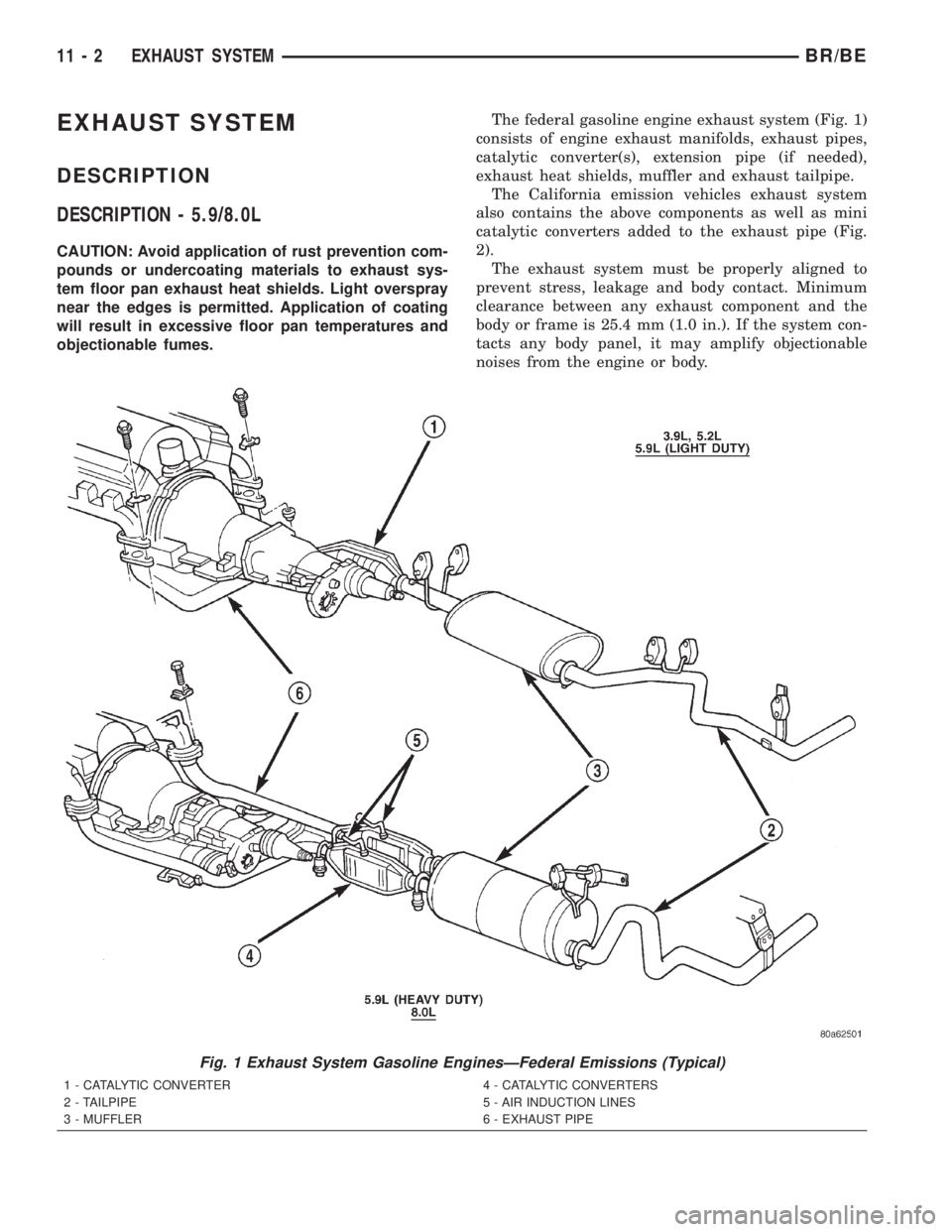
objectionable fumes.The federal gasoline engine exhaust system (Fig. 1)
consists of engine exhaust manifolds, exhaust pipes,
catalytic converter(s), extension pipe (if needed),
exhaust heat shields, muffler and exhaust tailpipe.
The California emission vehicles exhaust system
also contains the above components as well as mini
catalytic converters added to the exhaust pipe (Fig.
2).
The exhaust system must be properly aligned to
prevent stress, leakage and body contact. Minimum
clearance between any exhaust component and the
body or frame is 25.4 mm (1.0 in.). If the system con-
tacts any body panel, it may amplify objectionable
noises from the engine or body.
Fig. 1 Exhaust System Gasoline EnginesÐFederal Emissions (Typical)
1 - CATALYTIC CONVERTER
2 - TAILPIPE
3 - MUFFLER4 - CATALYTIC CONVERTERS
5 - AIR INDUCTION LINES
6 - EXHAUST PIPE
11 - 2 EXHAUST SYSTEMBR/BE
Page 1270 of 2255
DESCRIPTIONÐ5.9L DIESEL
CAUTION: Avoid application of rust prevention com-
pounds or undercoating materials to exhaust sys-
tem floor pan exhaust heat shields. Light overspray
near the edges is permitted. Application of coating
will result in excessive floor pan temperatures and
objectionable fumes.
The diesel engine exhaust system consists of an
engine exhaust manifold, turbocharger, exhaust pipe,
resonator, extension pipe (if needed), muffler and
exhaust tailpipe.
The exhaust system must be properly aligned to
prevent stress, leakage and body contact. The
exhaust components should be kept a minimum of
25.4 mm (1.0 in.) away from the body and frame. If
the system contacts any body panel, it may amplify
objectionable noises from the engine or body.
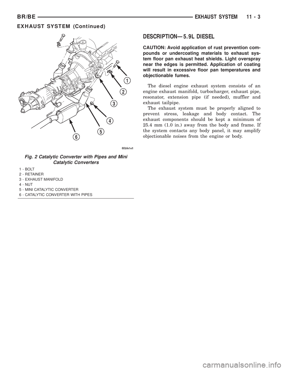
Fig. 2 Catalytic Converter with Pipes and Mini
Catalytic Converters
1 - BOLT
2 - RETAINER
3 - EXHAUST MANIFOLD
4 - NUT
5 - MINI CATALYTIC CONVERTER
6 - CATALYTIC CONVERTER WITH PIPES
BR/BEEXHAUST SYSTEM 11 - 3
EXHAUST SYSTEM (Continued)
Page 1271 of 2255
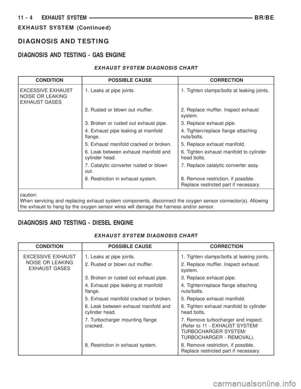
DIAGNOSIS AND TESTING
DIAGNOSIS AND TESTING - GAS ENGINE
EXHAUST SYSTEM DIAGNOSIS CHART
CONDITION POSSIBLE CAUSE CORRECTION
EXCESSIVE EXHAUST
NOISE OR LEAKING
EXHAUST GASES1. Leaks at pipe joints. 1. Tighten clamps/bolts at leaking joints.
2. Rusted or blown out muffler. 2. Replace muffler. Inspect exhaust
system.
3. Broken or rusted out exhaust pipe. 3. Replace exhaust pipe.
4. Exhaust pipe leaking at manifold
flange.4. Tighten/replace flange attaching
nuts/bolts.
5. Exhaust manifold cracked or broken. 5. Replace exhaust manifold.
6. Leak between exhaust manifold and
cylinder head.6. Tighten exhaust manifold to cylinder
head bolts.
7. Catalytic converter rusted or blown
out.7. Replace catalytic converter assy.
8. Restriction in exhaust system. 8. Remove restriction, if possible.
Replace restricted part if necessary.
caution:
When servicing and replacing exhaust system components, disconnect the oxygen sensor connector(s). Allowing
the exhaust to hang by the oxygen sensor wires will damage the harness and/or sensor.
DIAGNOSIS AND TESTING - DIESEL ENGINE
EXHAUST SYSTEM DIAGNOSIS CHART
CONDITION POSSIBLE CAUSE CORRECTION
EXCESSIVE EXHAUST
NOISE OR LEAKING
EXHAUST GASES1. Leaks at pipe joints. 1. Tighten clamps/bolts at leaking joints.
2. Rusted or blown out muffler. 2. Replace muffler. Inspect exhaust
system.
3. Broken or rusted out exhaust pipe. 3. Replace exhaust pipe.
4. Exhaust pipe leaking at manifold
flange.4. Tighten/replace flange attaching
nuts/bolts.
5. Exhaust manifold cracked or broken. 5. Replace exhaust manifold.
6. Leak between exhaust manifold and
cylinder head.6. Tighten exhaust manifold to cylinder
head bolts.
7. Turbocharger mounting flange
cracked.7. Remove turbocharger and inspect.
(Refer to 11 - EXHAUST SYSTEM/
TURBOCHARGER SYSTEM/
TURBOCHARGER - REMOVAL).
8. Restriction in exhaust system. 8. Remove restriction, if possible.
Replace restricted part if necessary.
11 - 4 EXHAUST SYSTEMBR/BE
EXHAUST SYSTEM (Continued)
Page 1272 of 2255
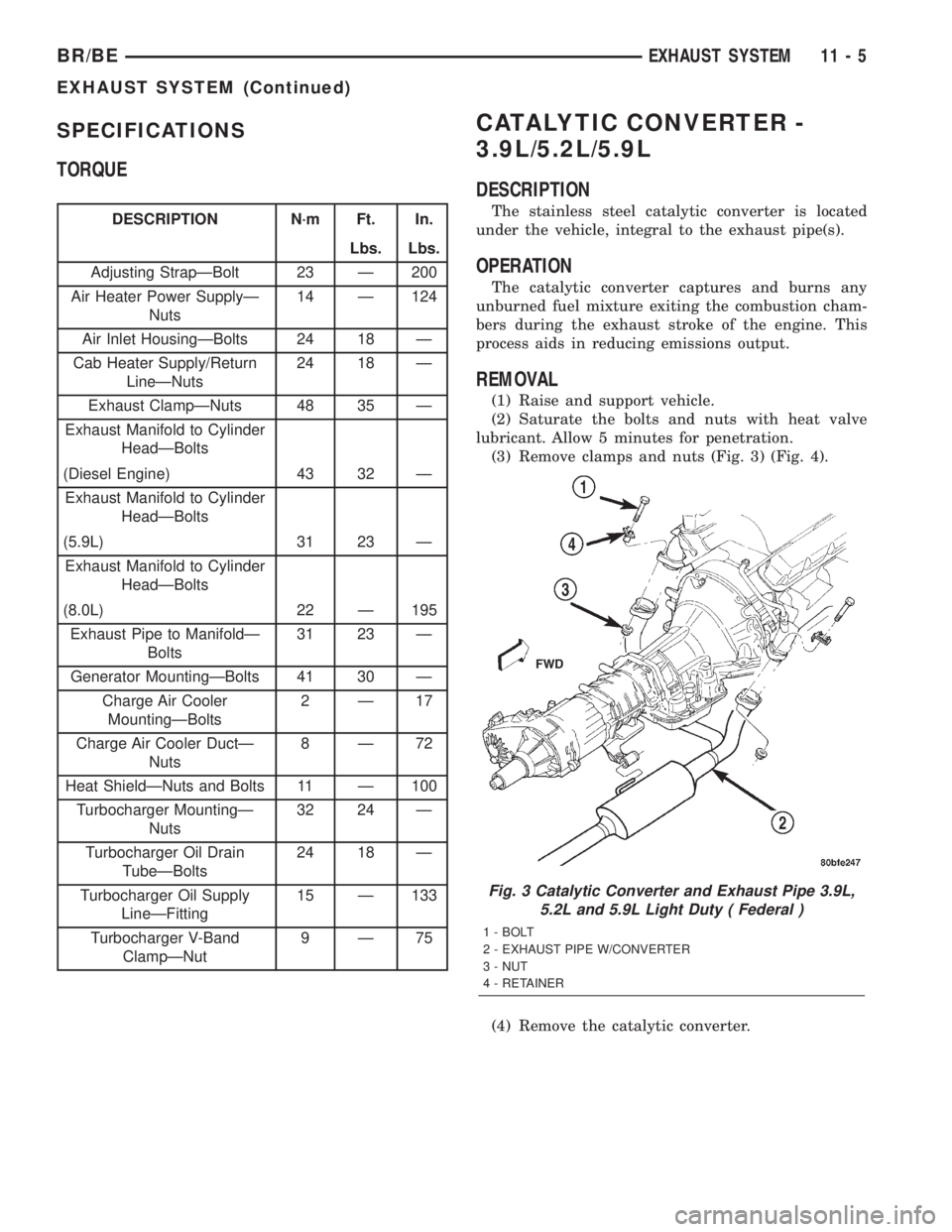
SPECIFICATIONS
TORQUE
DESCRIPTION N´m Ft. In.
Lbs. Lbs.
Adjusting StrapÐBolt 23 Ð 200
Air Heater Power SupplyÐ
Nuts14 Ð 124
Air Inlet HousingÐBolts 24 18 Ð
Cab Heater Supply/Return
LineÐNuts24 18 Ð
Exhaust ClampÐNuts 48 35 Ð
Exhaust Manifold to Cylinder
HeadÐBolts
(Diesel Engine) 43 32 Ð
Exhaust Manifold to Cylinder
HeadÐBolts
(5.9L) 31 23 Ð
Exhaust Manifold to Cylinder
HeadÐBolts
(8.0L) 22 Ð 195
Exhaust Pipe to ManifoldÐ
Bolts31 23 Ð
Generator MountingÐBolts 41 30 Ð
Charge Air Cooler
MountingÐBolts2Ð17
Charge Air Cooler DuctÐ
Nuts8Ð72
Heat ShieldÐNuts and Bolts 11 Ð 100
Turbocharger MountingÐ
Nuts32 24 Ð
Turbocharger Oil Drain
TubeÐBolts24 18 Ð
Turbocharger Oil Supply
LineÐFitting15 Ð 133
Turbocharger V-Band
ClampÐNut9Ð75
CATALYTIC CONVERTER -
3.9L/5.2L/5.9L
DESCRIPTION
The stainless steel catalytic converter is located
under the vehicle, integral to the exhaust pipe(s).
OPERATION
The catalytic converter captures and burns any
unburned fuel mixture exiting the combustion cham-
bers during the exhaust stroke of the engine. This
process aids in reducing emissions output.
REMOVAL
(1) Raise and support vehicle.
(2) Saturate the bolts and nuts with heat valve
lubricant. Allow 5 minutes for penetration.
(3) Remove clamps and nuts (Fig. 3) (Fig. 4).
(4) Remove the catalytic converter.
Fig. 3 Catalytic Converter and Exhaust Pipe 3.9L,
5.2L and 5.9L Light Duty ( Federal )
1 - BOLT
2 - EXHAUST PIPE W/CONVERTER
3 - NUT
4 - RETAINER
BR/BEEXHAUST SYSTEM 11 - 5
EXHAUST SYSTEM (Continued)
Page 1273 of 2255
INSPECTION
Look at the stainless steel body of the converter,
inspect for bulging or other distortion that could be a
result of overheating. If the converter has a heat
shield attached make sure it is not bent or loose.
If you suspect internal damage to the catalyst, tap-
ping the bottom of the catalyst with a rubber mallet
may indicate a damaged core.
INSTALLATION
(1) Assemble converter and clamps loosely in
place.
(2) Install the exhaust pipe onto exhaust mani-
folds, tighten 31 N´m (23 ft. lbs.).
(3) Tighten all clamp nuts to 48 N´m (35 ft. lbs.)
torque.
(4) Lower the vehicle.
(5) Start the engine and inspect for exhaust leaks
and exhaust system contact with the body panels. A
minimum of 25.4 mm (1.0 in.) is required between
exhaust system components and body/frame parts.
Adjust the alignment, if needed.
CATALYTIC CONVERTER - 5.9L
HD/8.0L
DESCRIPTION
The stainless steel catalytic converter is located
under the vehicle, attached to the exhaust pipe(s).
OPERATION
The catalytic converter captures and burns any
unburned fuel mixture exiting the combustion cham-
bers during the exhaust stroke of the engine. This
process aids in reducing emissions output.
REMOVAL
(1) Raise and support vehicle.
(2) Saturate the bolts and nuts with heat valve
lubricant. Allow 5 minutes for penetration.
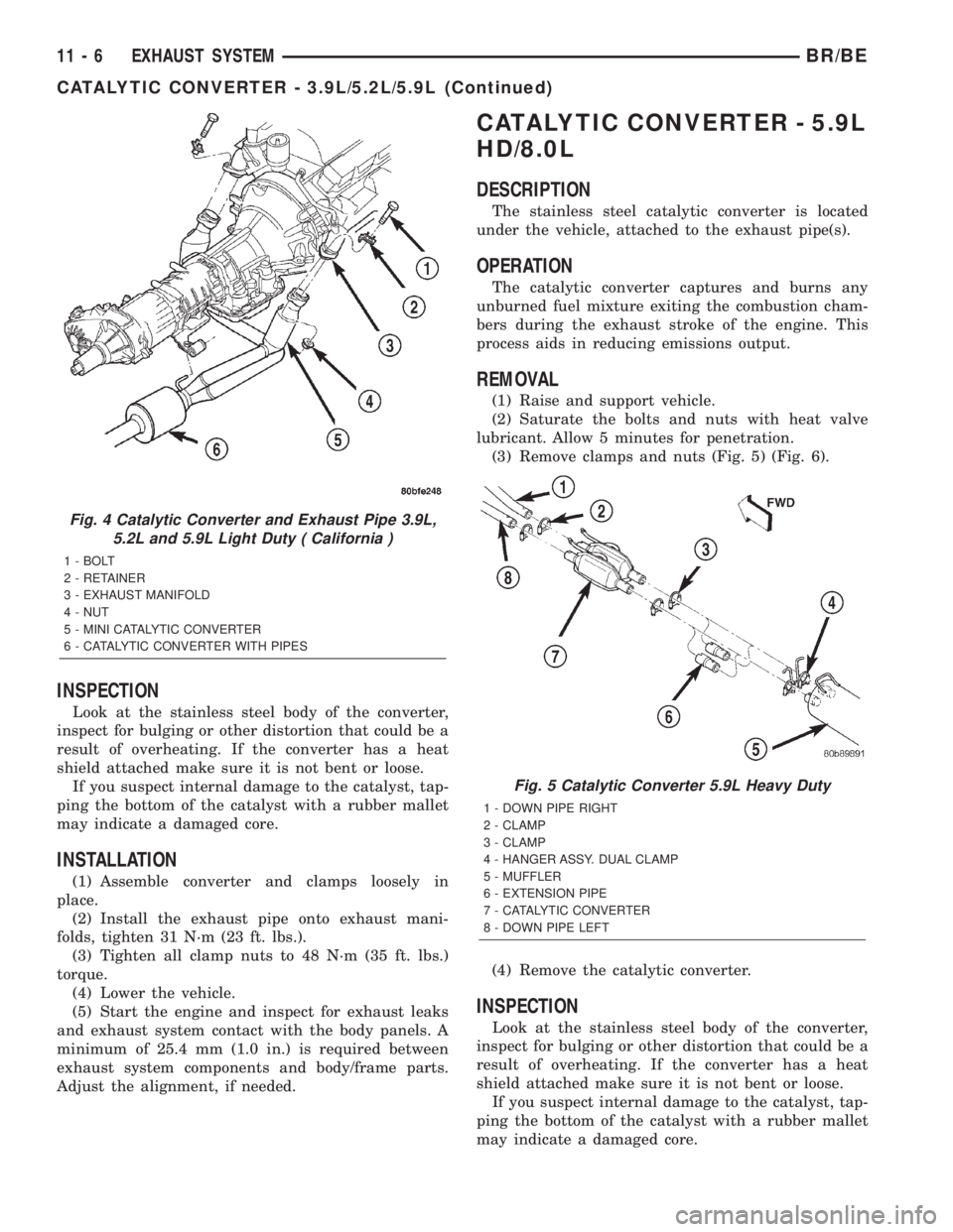
(3) Remove clamps and nuts (Fig. 5) (Fig. 6).
(4) Remove the catalytic converter.
INSPECTION
Look at the stainless steel body of the converter,
inspect for bulging or other distortion that could be a
result of overheating. If the converter has a heat
shield attached make sure it is not bent or loose.
If you suspect internal damage to the catalyst, tap-
ping the bottom of the catalyst with a rubber mallet
may indicate a damaged core.
Fig. 4 Catalytic Converter and Exhaust Pipe 3.9L,
5.2L and 5.9L Light Duty ( California )
1 - BOLT
2 - RETAINER
3 - EXHAUST MANIFOLD
4 - NUT
5 - MINI CATALYTIC CONVERTER
6 - CATALYTIC CONVERTER WITH PIPES
Fig. 5 Catalytic Converter 5.9L Heavy Duty
1 - DOWN PIPE RIGHT
2 - CLAMP
3 - CLAMP
4 - HANGER ASSY. DUAL CLAMP
5 - MUFFLER
6 - EXTENSION PIPE
7 - CATALYTIC CONVERTER
8 - DOWN PIPE LEFT
11 - 6 EXHAUST SYSTEMBR/BE
CATALYTIC CONVERTER - 3.9L/5.2L/5.9L (Continued)